Week 7-12-Creation of 1D Connectors Challenge
Objective:
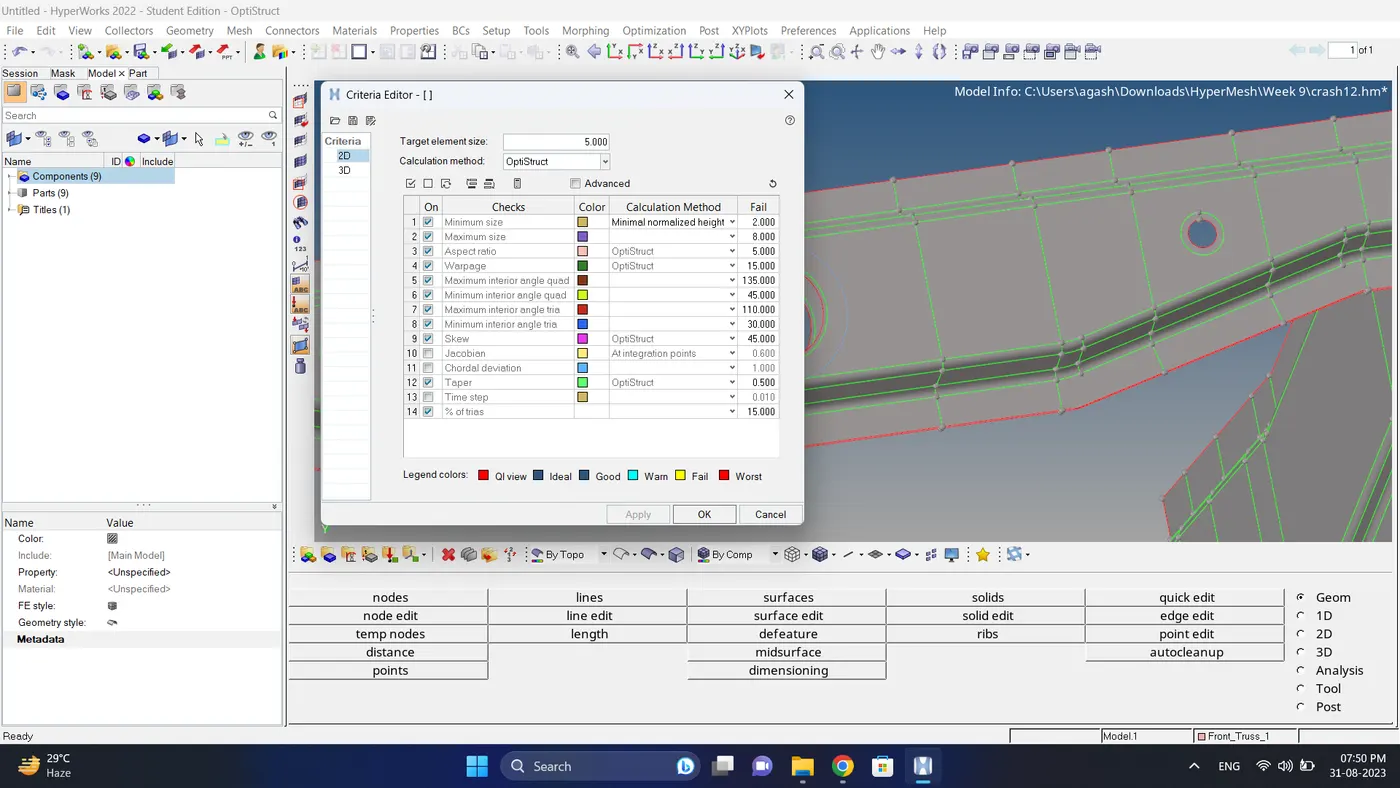
1. Mesh the component with the quality criteria, given below
Target Element size - 5 Units
|
S.N |
Quality Criteria |
Value |
|
1 |
Aspect Ratio |
5 |
|
2 |
Skewness |
45 |
|
3 |
Warping |
15 |
|
4 |
Taper |
0.5 |
|
5 |
Min. Length |
2 Units |
|
6 |
Max. Length |
8 Units |
|
7 |
Min angle Quad |
45 |
|
8 |
Max angle Quad |
135 |
|
9 |
Min angle Tria |
30 |
|
10 |
Max angle Tria |
110 |
|
10 |
Tria % |
15 |
2. Create a connector and Attach the various parts of the given model
- Right Rail 2 & Front truss 1:- Seam-Quad(angled+capped+L)
- Left Rail 2 & Front truss 1:- Quad elements
- Front truss 2, Front truss 1 & Right Rail 1:- Spot weld with 2 Layers and 5 mm Diameter
- Front truss 2, Front truss 1 & Left Rail 1:- Hexa (Adhesive)
- Rear truss 2 & Right Rail 2:- Bolt Connector
- Rear truss 2 & Left Rail 2:- Bolt Connector
- Right Rail 1 & Right Rail 2:- Spot-weld with Rigid Elements
- Left Rail 1 & Left Rail 2:- Spot-weld with Spring Elements
- Rest all the components left Join them with suitable connectors
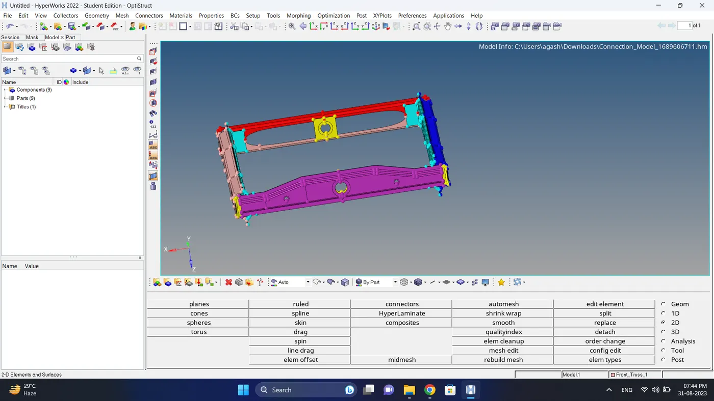
Initial Model Image:
Procedure:
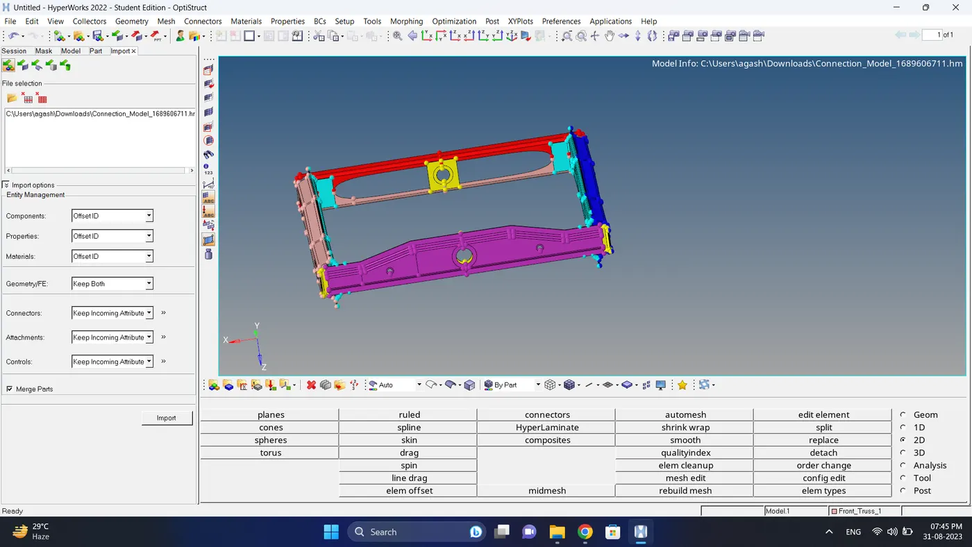
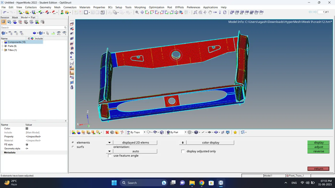
1. Import the Model.
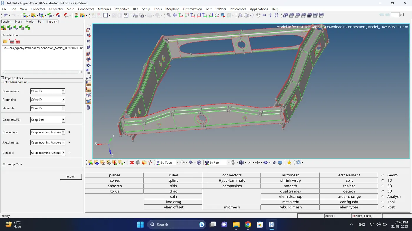
2. Do visual inspection and if required do geometry cleanup.
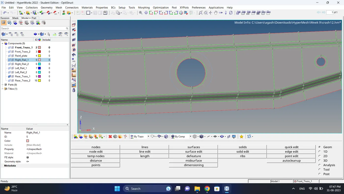
3. Input the quality criteria.
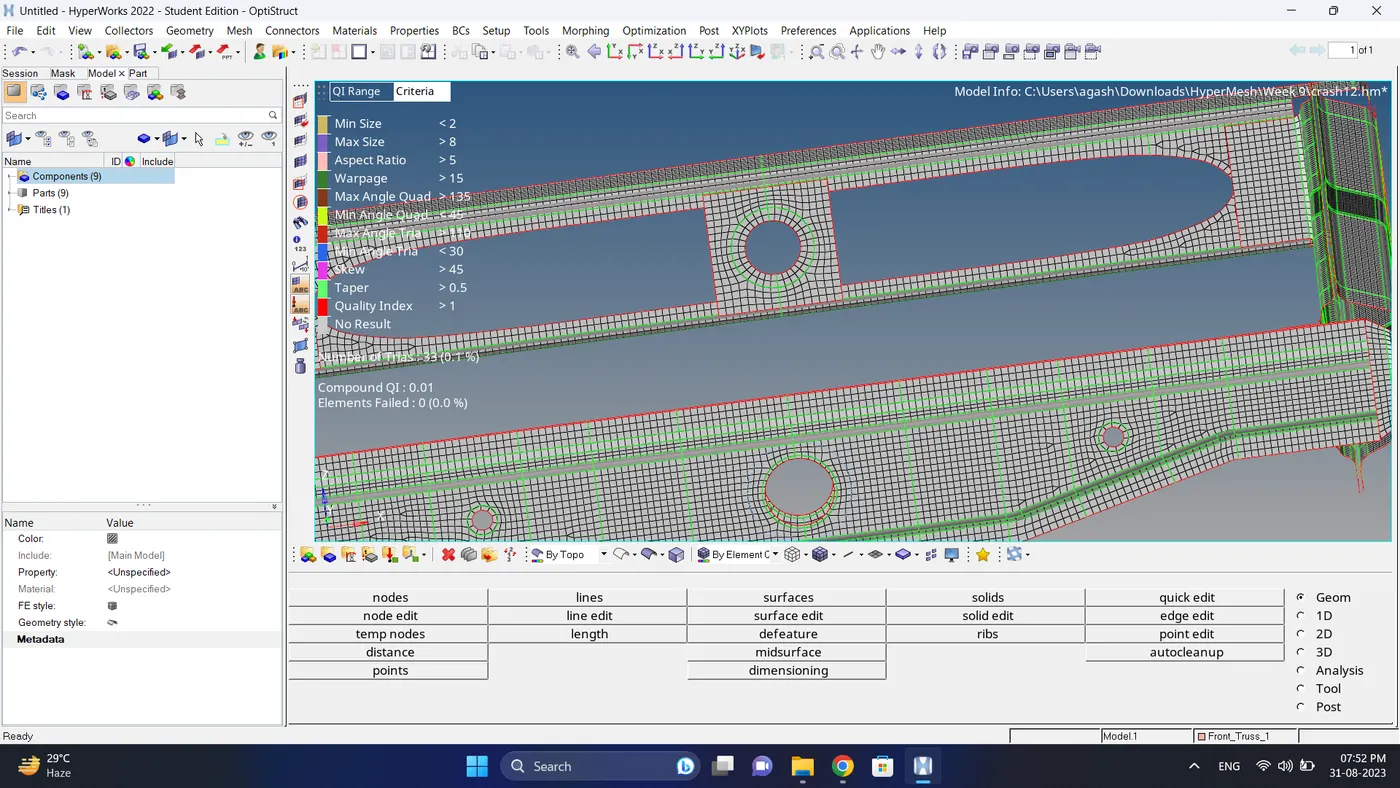
4. Mesh the model while fixing mesh flow and quality criteria.
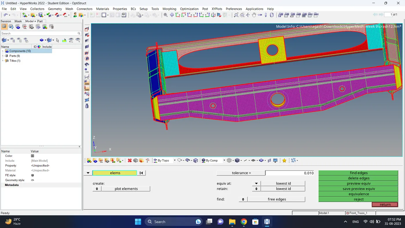
5. Check for free edges if necessary equivalance it using Tool-Edges option.
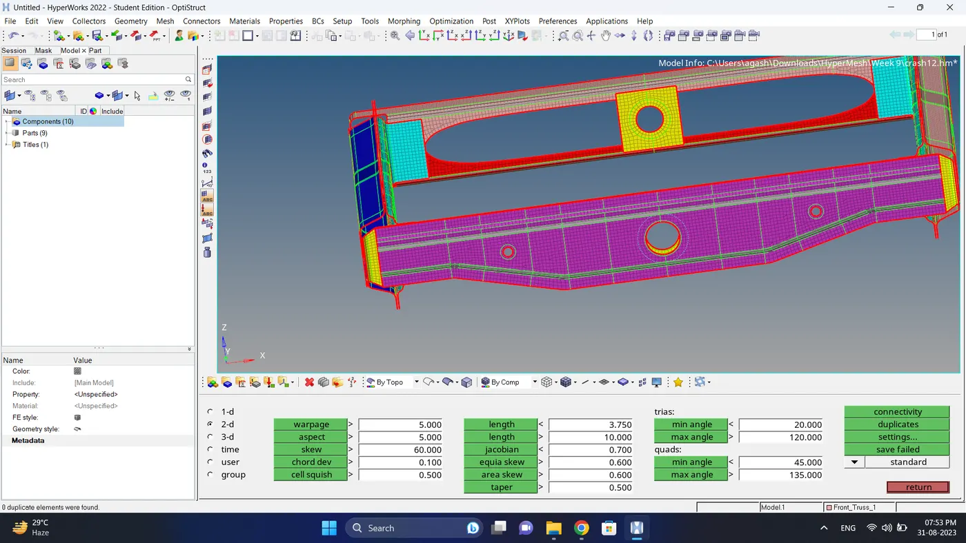
6. Check for the duplicate elements and if there are duplicate delete them.
7. Check normals for mid surface, if needed adjust them.
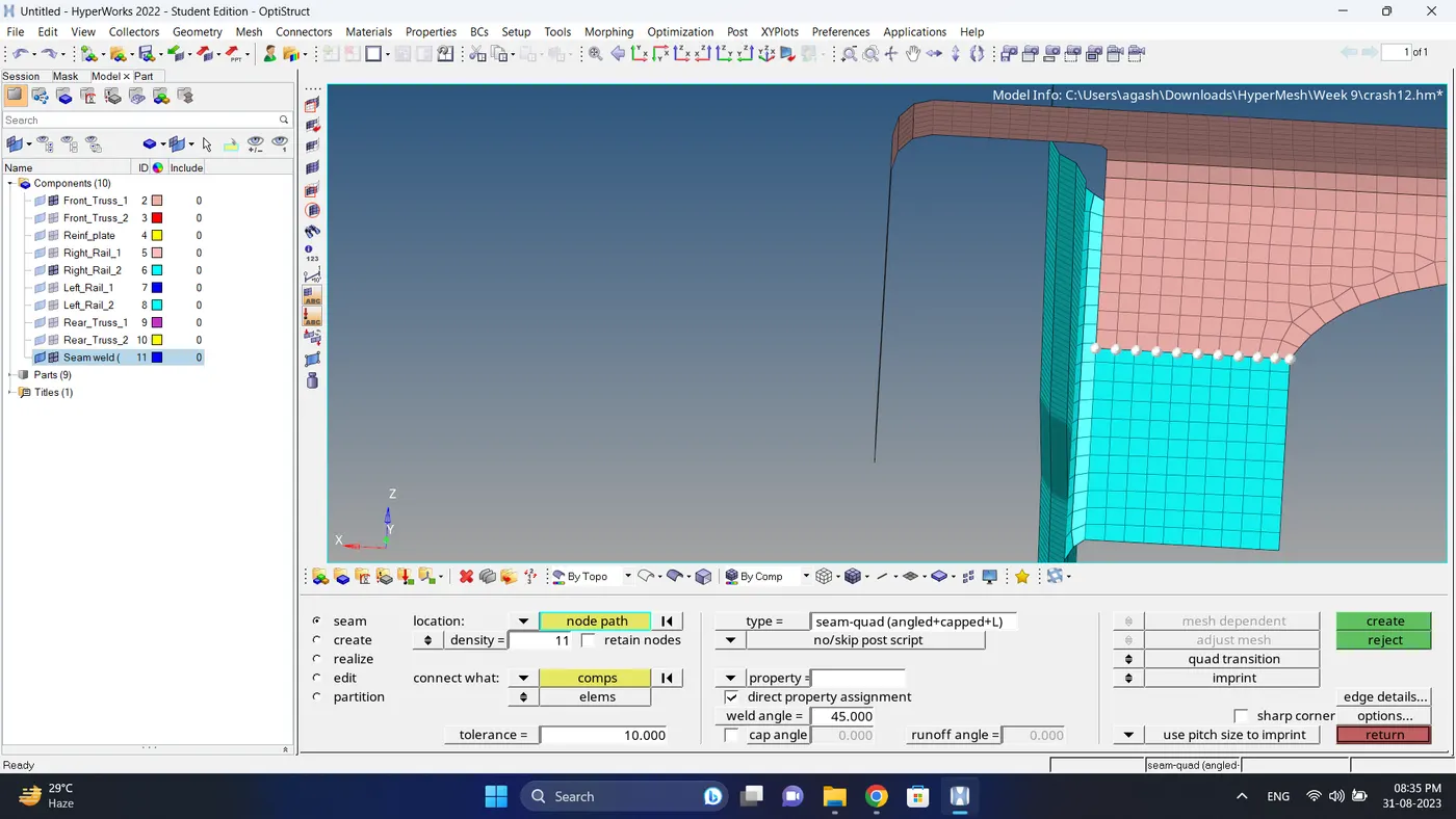
8. Create a connection between Right Rail 2 & Front truss 1 with Seam-Quad(angled+capped+L)
a. Go to 2d - Connectors - seam - select node - select both component - select type to seam-quad (angled+capped+L)
- give density - change remesh to quad transition - click create.
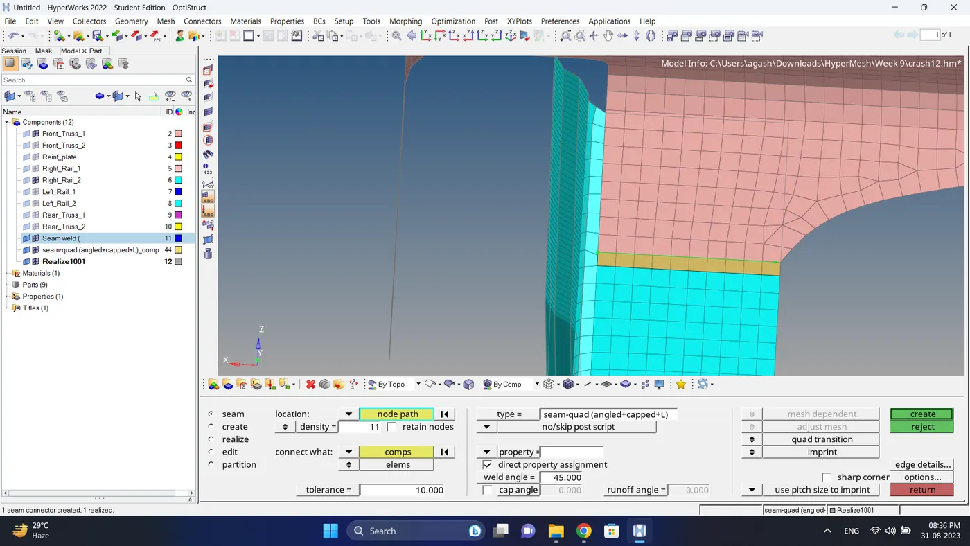
b. After creating connector some element will get distorted so fix the quality and smooth the mesh.
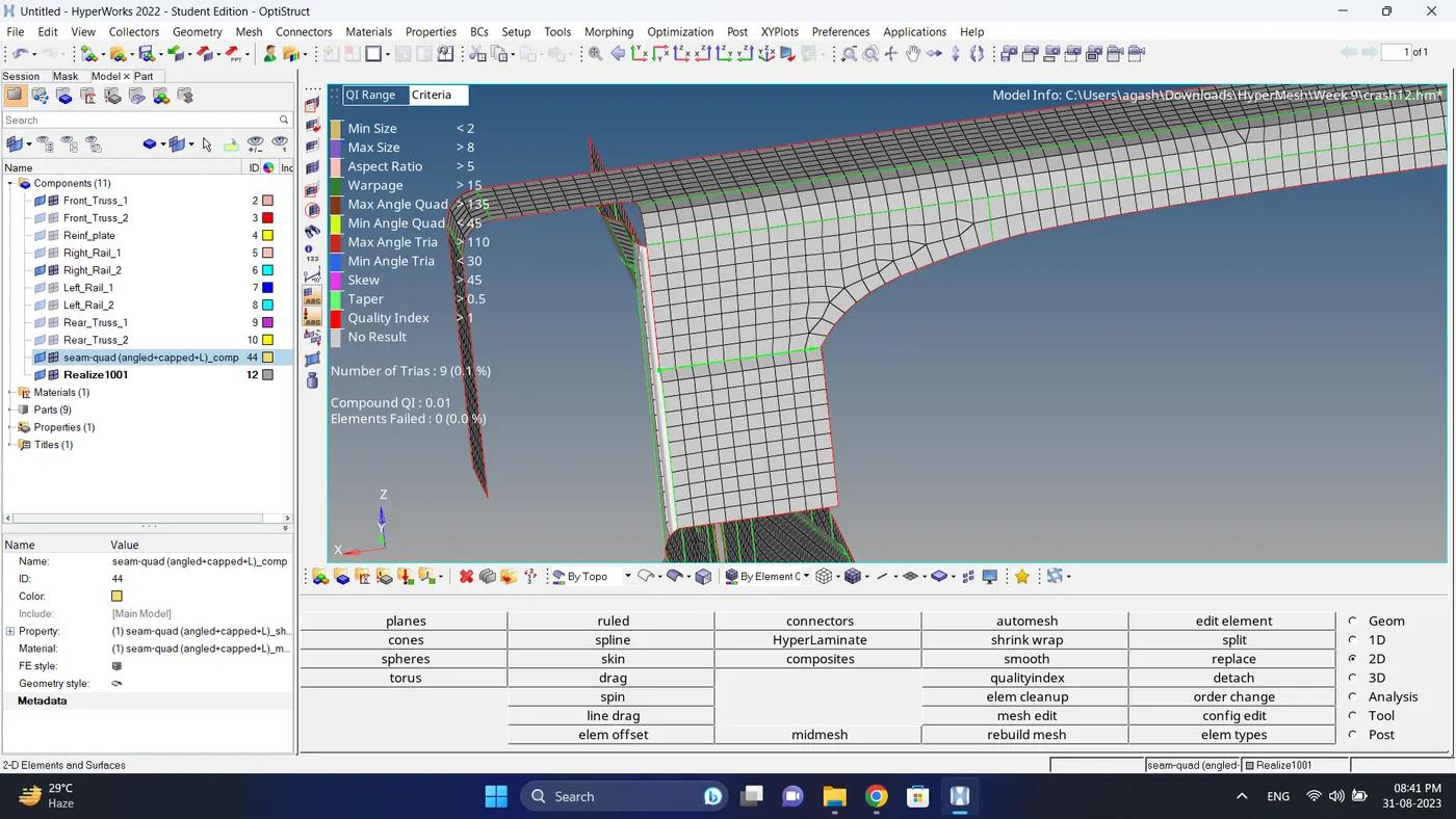
9. Create a connection between Left Rail 2 & Front truss 1 with quad elements.
a. Go to 2d - Connectors - seam - select node - select both component - select type to quad - give density - change remesh to quad transition - click create.
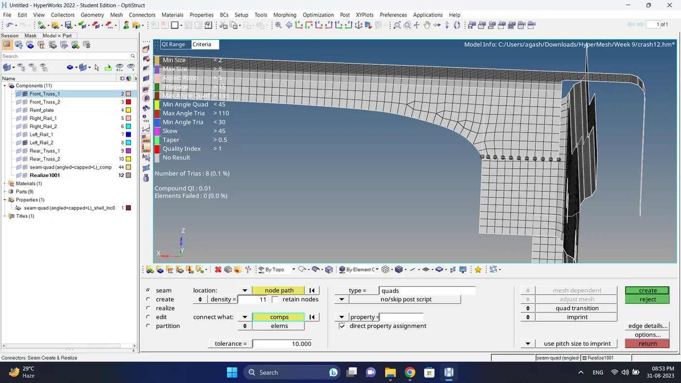
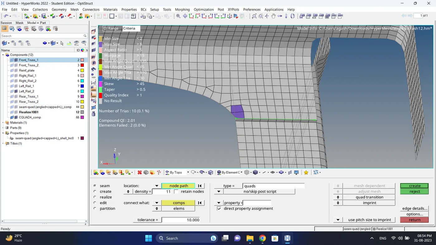
b. After creating connector some element will get distorted so fix the quality and smooth the mesh.
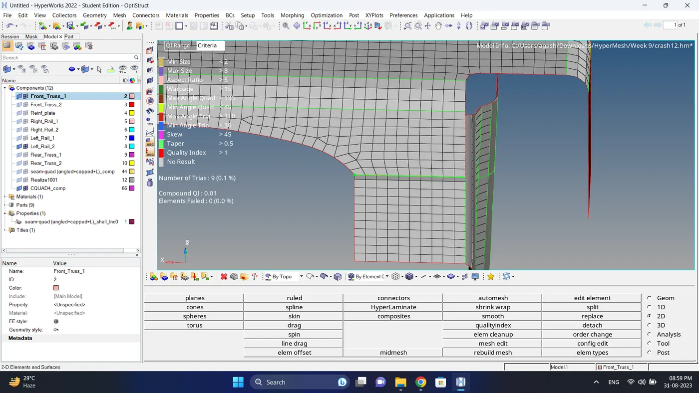
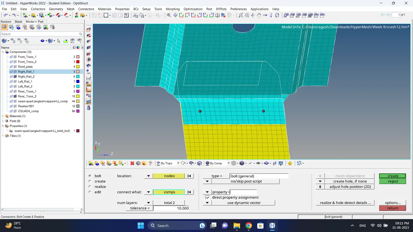
10. Create a connection between Rear truss 2 & Right Rail 2 with Bolt Connector.
a. Go to 2d - connectors - bolt - select nodes - select componet - since there hole is not present change existing hole only to create hole, if none - give number of layers - give tolerance - click create.
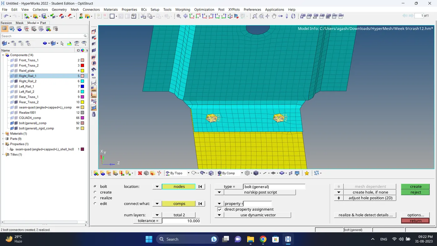
b. After creating connector some element will get distorted so fix the quality and smooth the mesh.
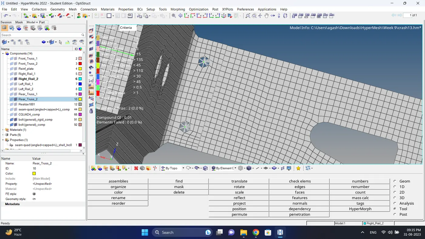
11. Create a connection between Rear truss 2 & Left Rail 2 with Bolt Connector.
a. Go to 2d - connectors - bolt - select nodes - select componet - since there hole is not present change existing hole only to create hole, if none - give number of layers - give tolerance - click create.
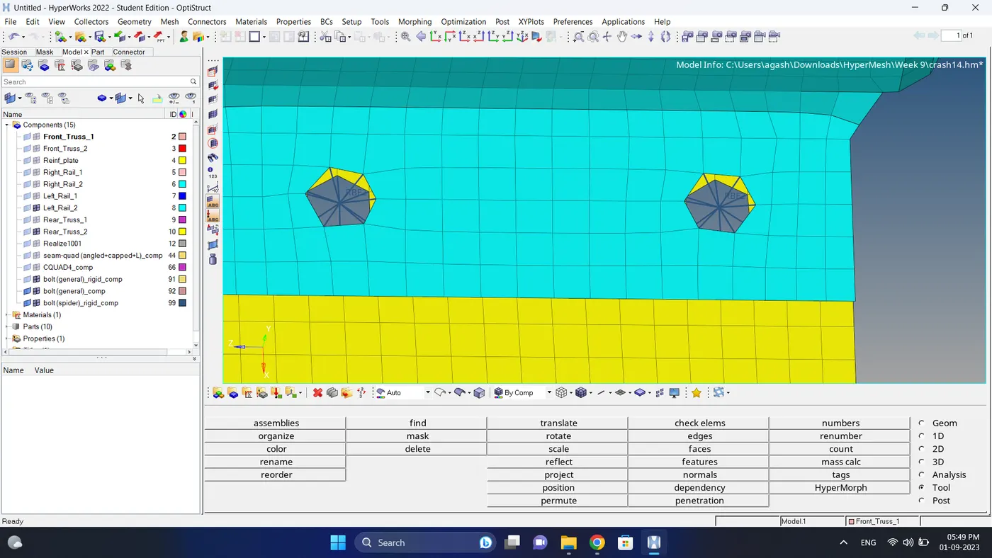
b. After creating connector some element will get distorted so fix the quality and smooth the mesh.
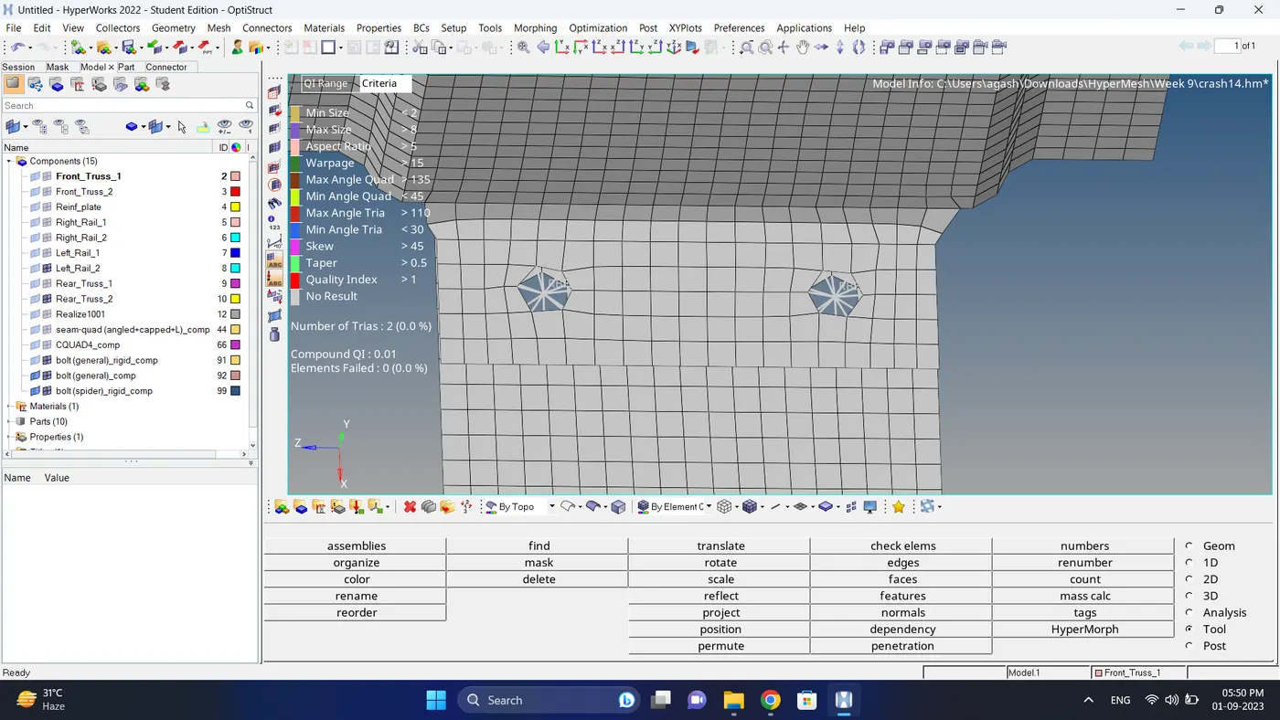
12. Create a connection between Front truss 2, Front truss 1 & Right Rail 1 with Spot weld, 2 Layers and 5 mm Diameter.
a. Go to 2d - connectors - spot - select nodes - select components - give tolerance value - give diameter value - change num layer to total 3 - click create
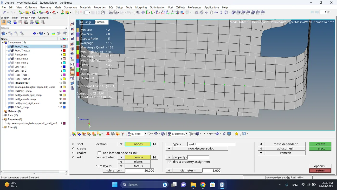
b. After creating connector some element will get distorted so fix the quality and smooth the mesh.
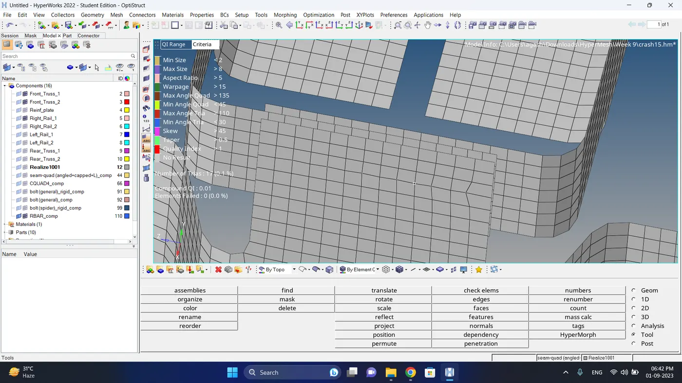
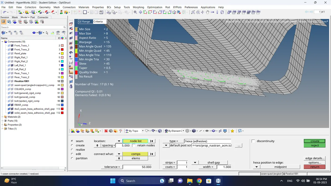
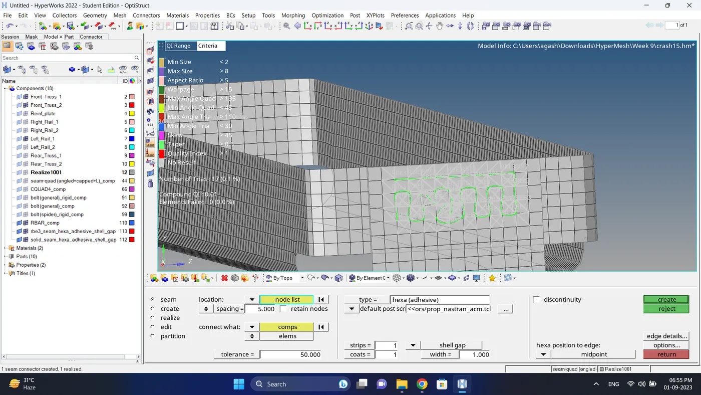
13. Create a connection between Front truss 2, Front truss 1 & Left Rail 1 with Hexa (Adhesive).
a. Go to 2d - Connectors - seam - select node - select both component - select type to hexa (adhesive) - give spacing - - click create.
Note: first create connection between Front truss 1 & Front truss 2 then Front truss 1& Left rail 1
14. Create a connection between Right Rail 1 & Right Rail 2 with Spot-weld, Rigid Elements.
a. Go to 2d - connectors - spot - select nodes - select components - give tolerance value - change num layer to total 2 - click create
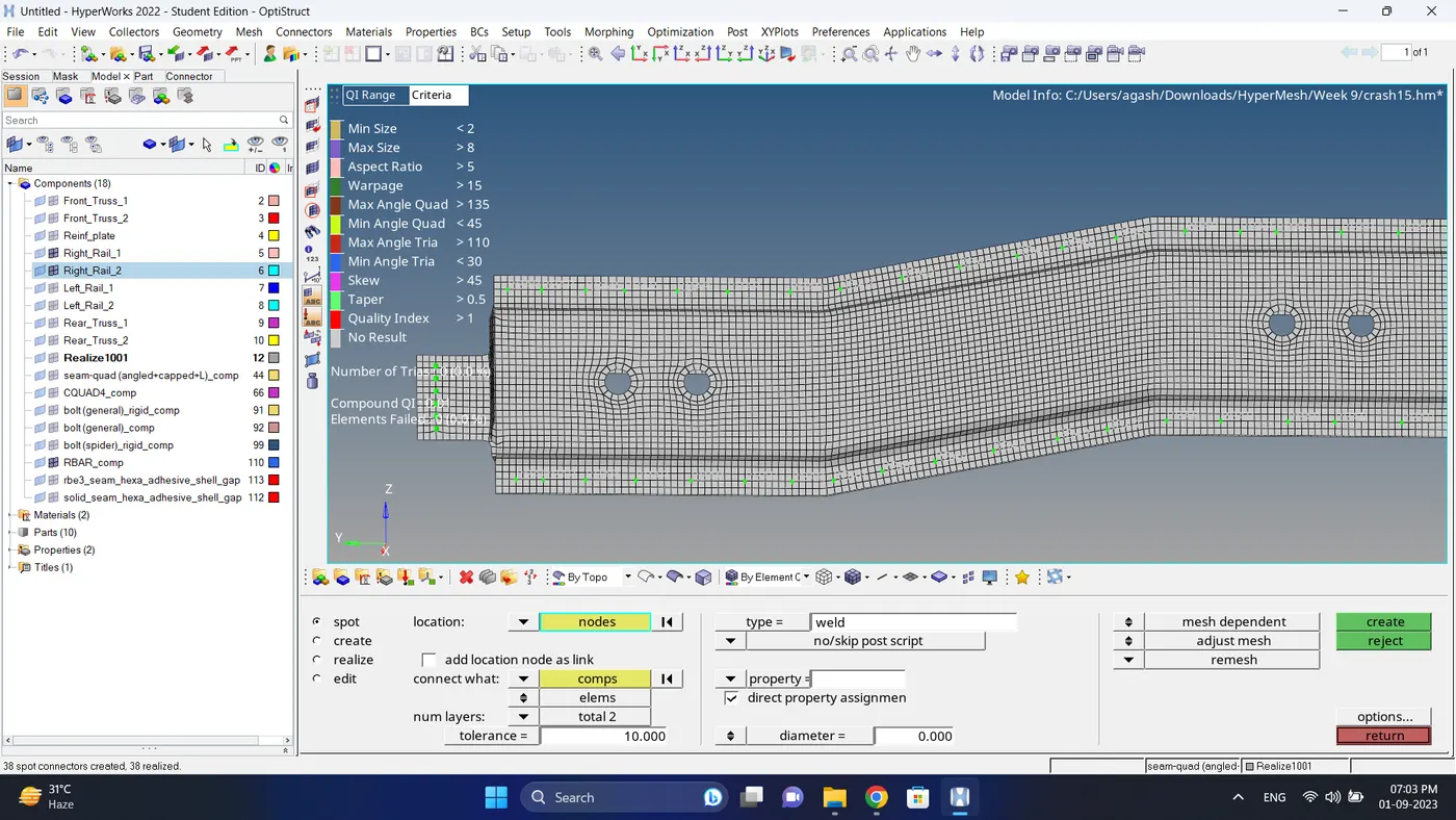
b. After creating connector some element will get distorted so fix the quality and smooth the mesh.
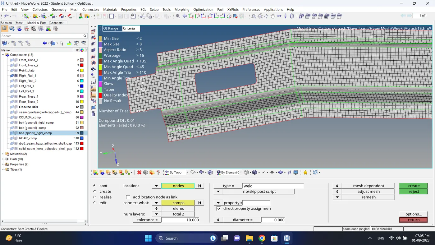
15. Create a connection between Left Rail 1 & Left Rail 2 with Spot weld, Spring Elements.
a. Go to 2d - connectors - spot - select nodes - select components - give tolerance value - give diameter value - click create
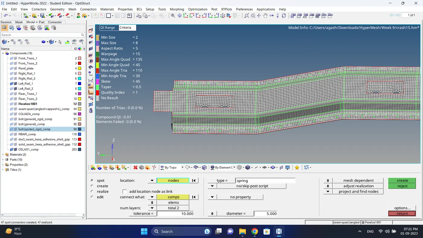
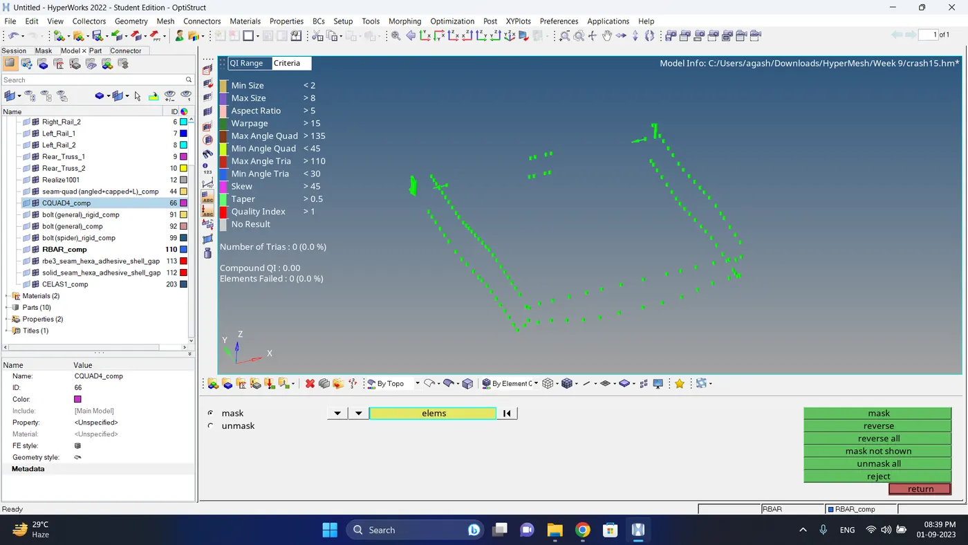
16. Check if the all the elements are connected to each by first visibling all the element - go to mask - select single element - click on the element box and select by attached - click mask.
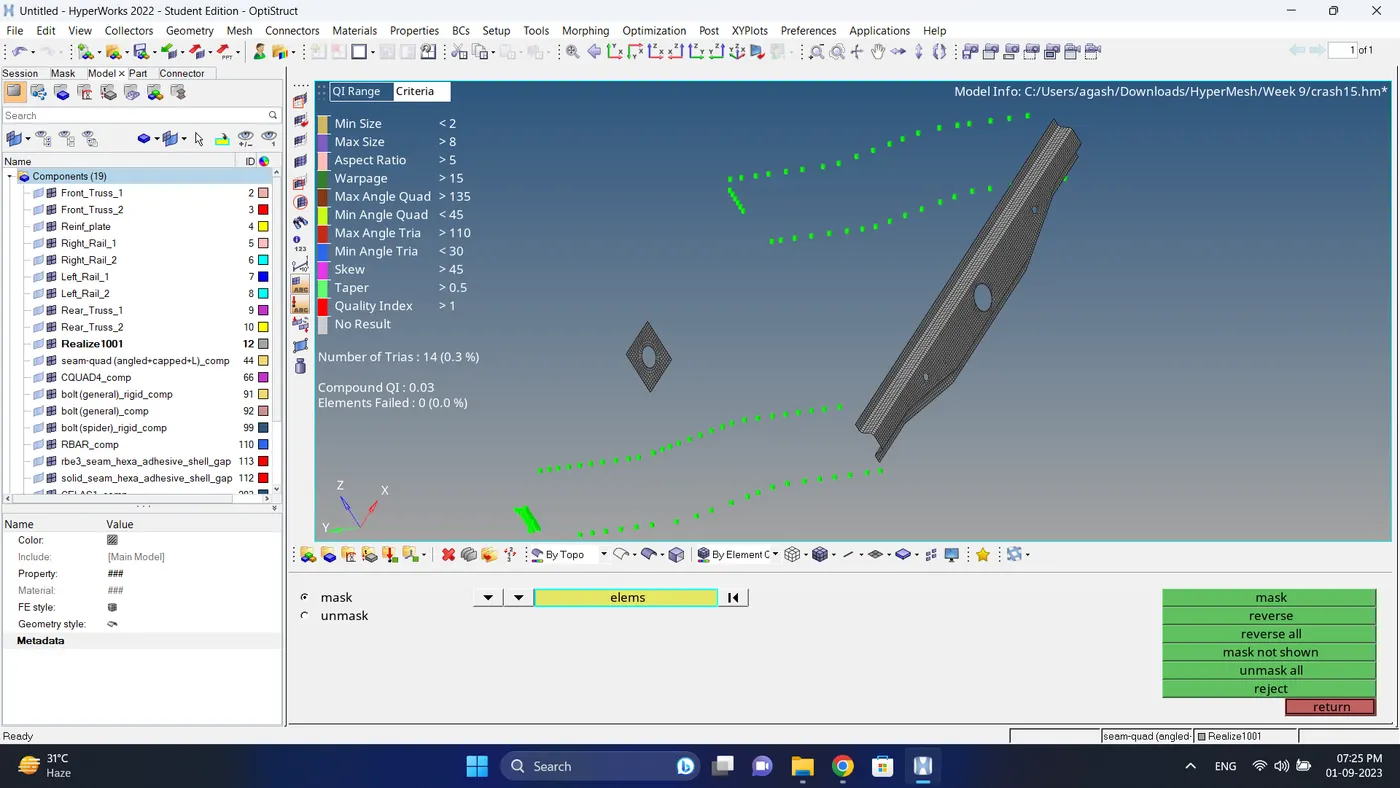
17. Those element which are not connected join them with suitable connectors.
18. Create a connection between Reinf plate, Front truss 1 and Front truss 2 with spot weld.
a. Go to 2d - connectors - spot - select nodes - select components - give tolerance value - give diameter value - click create.
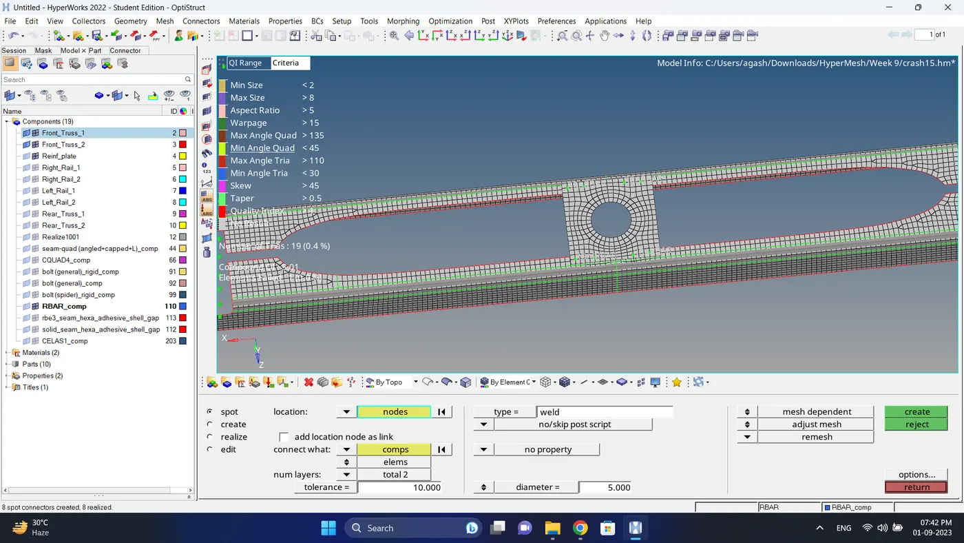
b. After creating connector some element will get distorted so fix the quality and smooth the mesh.
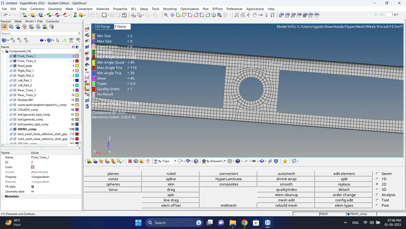
19. Create a connection between Rear truss 1 and Rear truss 2 with spot weld.
a. Go to 2d - connectors - spot - select nodes - select components - give tolerance value - give diameter value - click create.
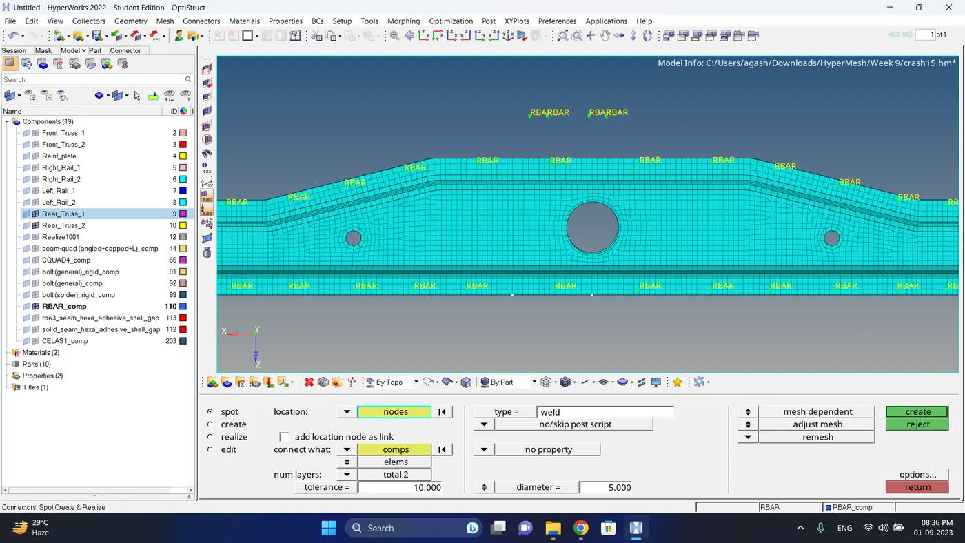
b. After creating connector some element will get distorted so fix the quality and smooth the mesh.
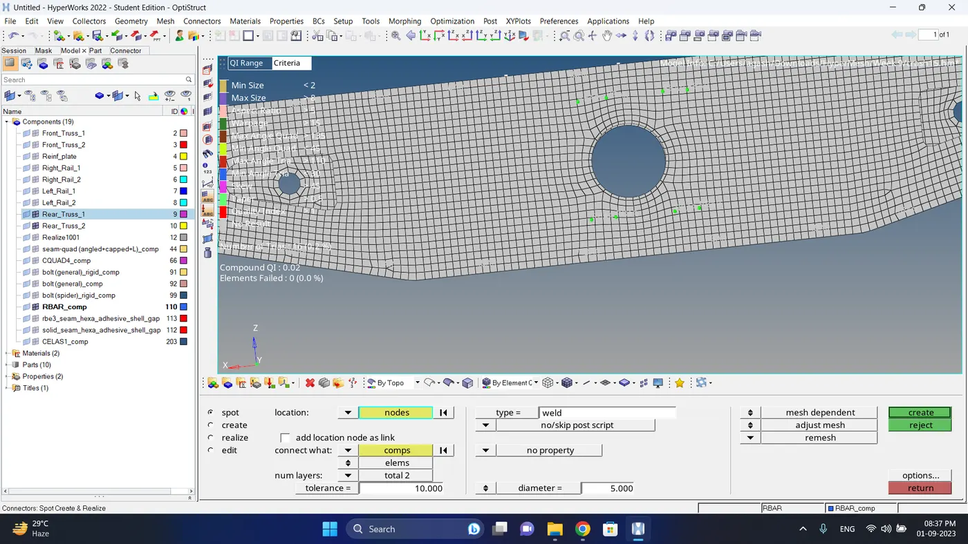
20. Again Check if the all the elements are connected to each by first visibling all the element - go to mask - select single element - click on the element box and select by attached - click mask.
Since mesh is all hidden then all the component are successfully attached to each others.
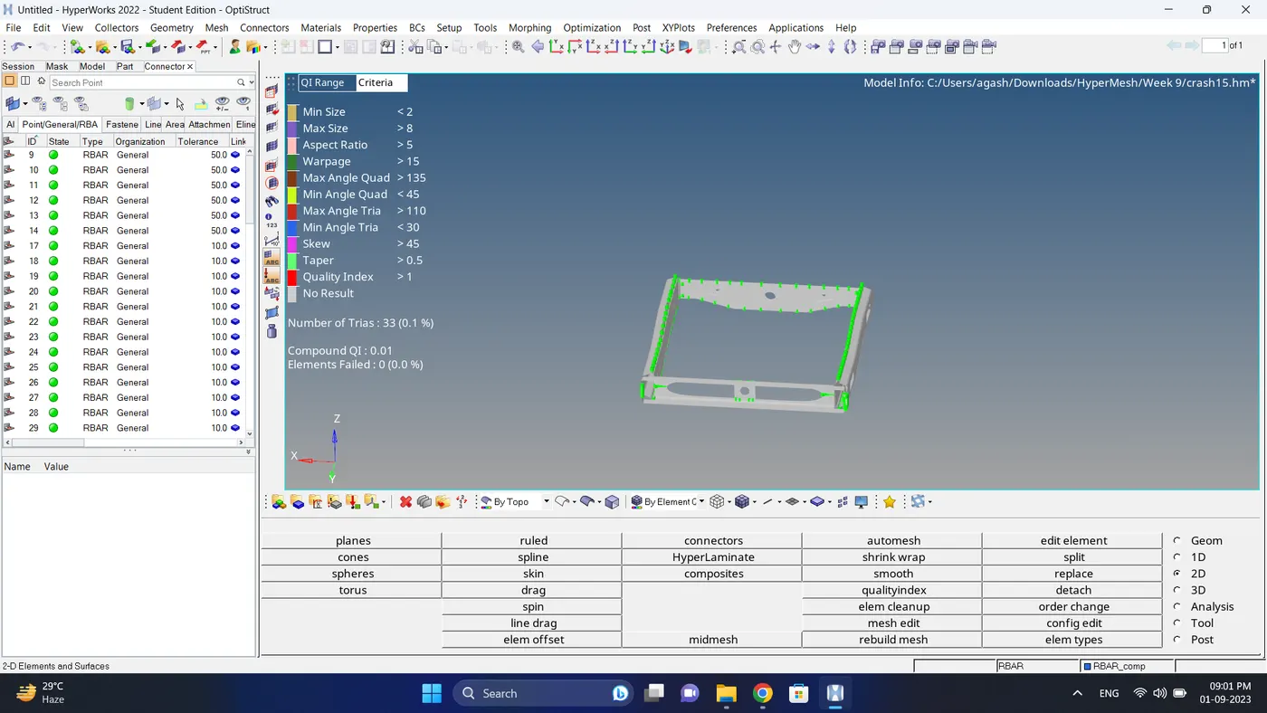
21. Open Connection manager, go to view - browser - hypermesh - connector, check if all the connector are realize.
Note : if state is green then its realize and if state is red then its not realize.
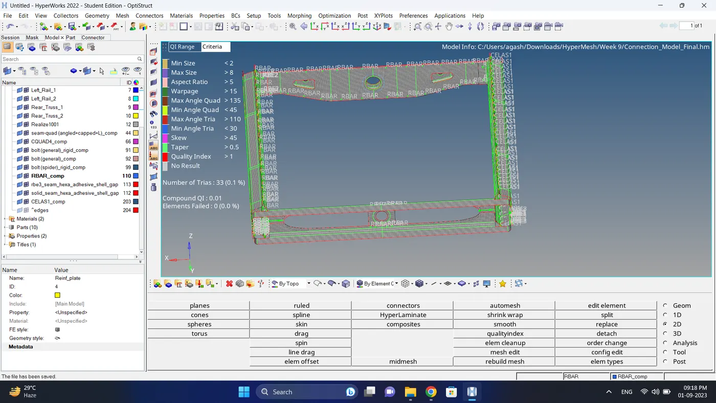
Final Model Image:
Result:
Meshing of the Model is done successfully as per given mesh parameters and Creating the connectors as per given connections connectors are done successfully.