Week 7-12-Creation of 1D Connectors Challenge
Aim:- The aim of this challenge is to create mesh on the components of the assembly and then make connections between them as per the requirement specified
Procedure:- To start working with the model, first we'll import the Model into the hyper mesh environment. This can be done by using import model option. After this we will inspect the geometry for any geometrical errors. This can be done by visually inspecting the model.
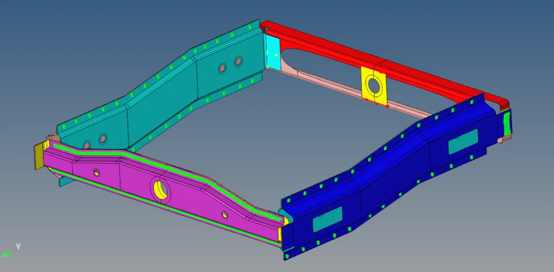
Figure 1: Showing the imported geometry into the hypermesh.
After fixing the geometrical errors, we will improve the geometry by splitting the surface and creating washer surfaces around holes This is done to improve the mesh flow across the geometry.
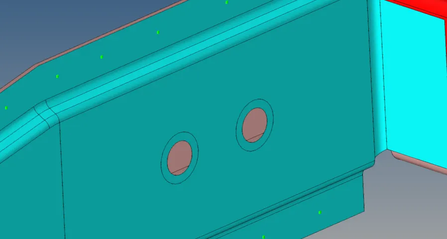
Figure 2: Showing split washer surfaces across holes.
After making a required changes into the geometry, we will start meshing. To start the mesh, we will use automesh, by selecting surfaces one by one.
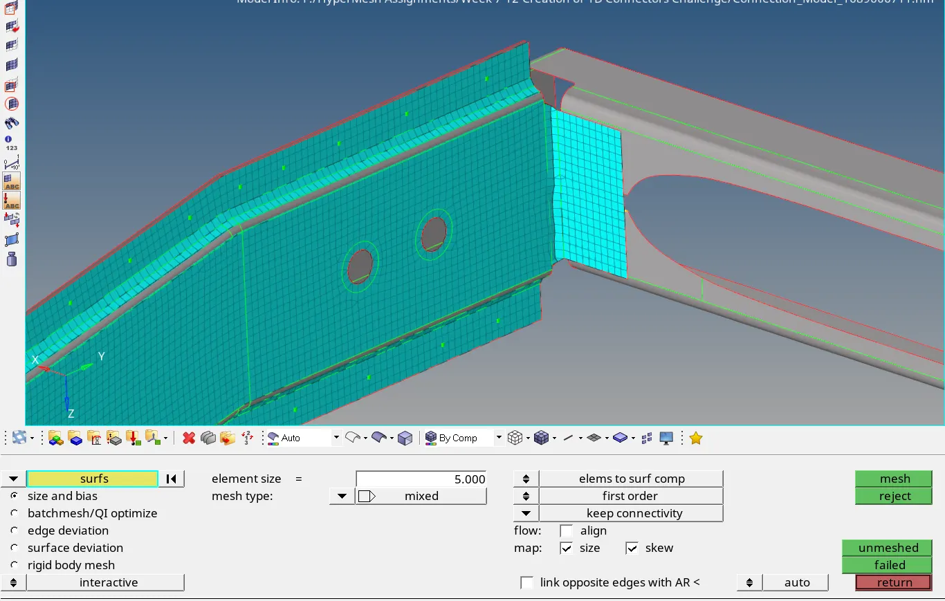
Figure 3: Showing meshed component using automesh command.
We will mesh all the components using same way. While meshing the components, we also have to monitor the quality of the elements. This can be done by setting the elements view to quality option.
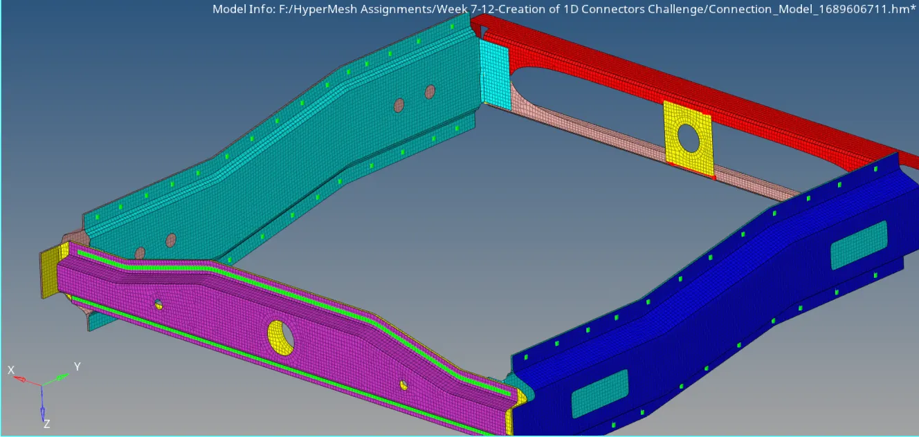
Figure 4: Showing created mesh of the assembly components
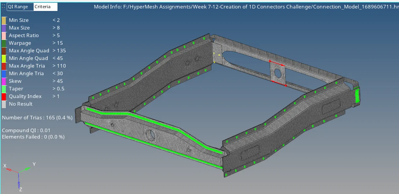
Figure 5: Showing elements in quality option.
After creating mesh, we'll start creating connections. For this we will use Connectors option available in 3D commands window.
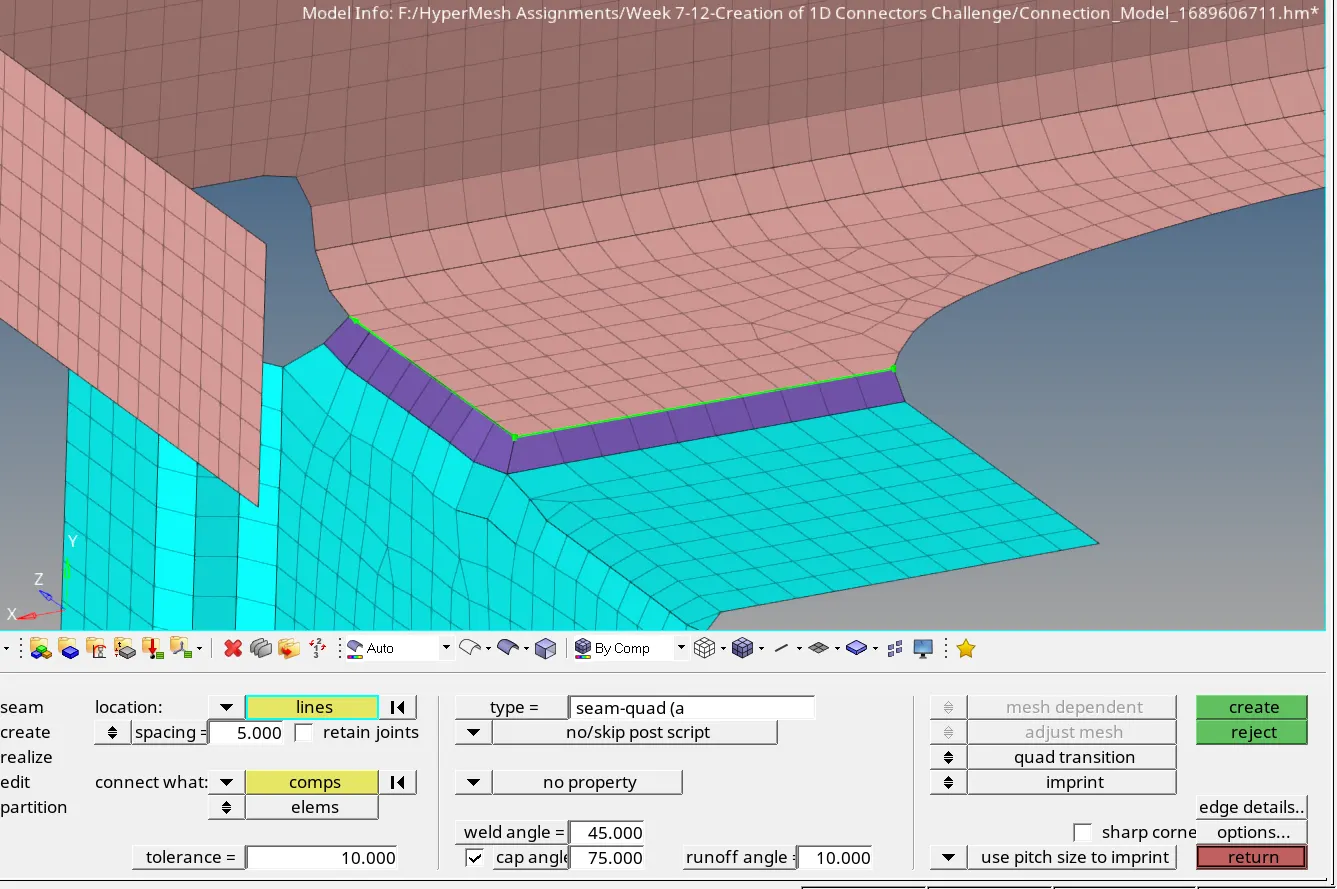
Figure 6: showing Seam Quad (angle+capped+L) elements use for connecting two parts.
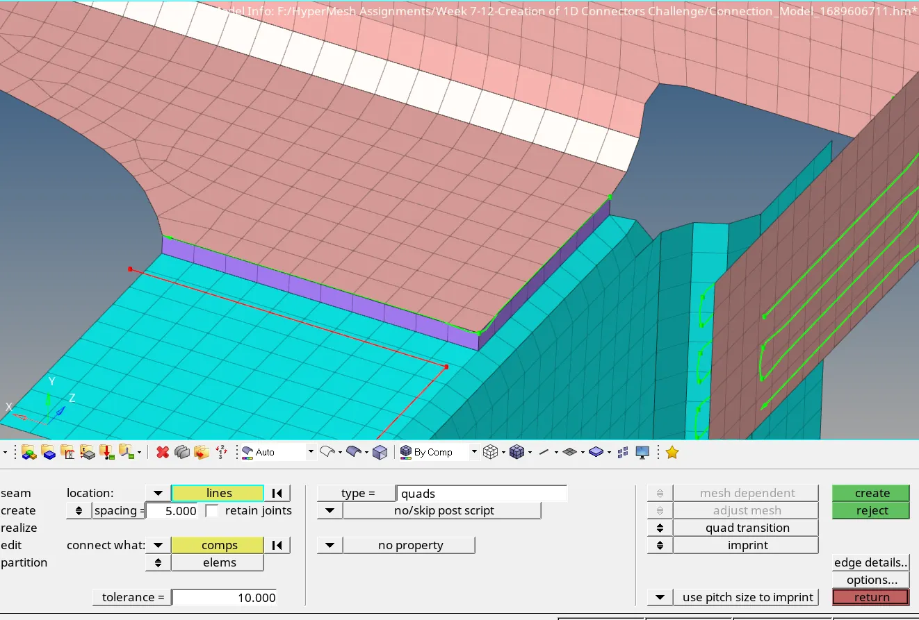
Figure 7: Showing seam with Quad elements
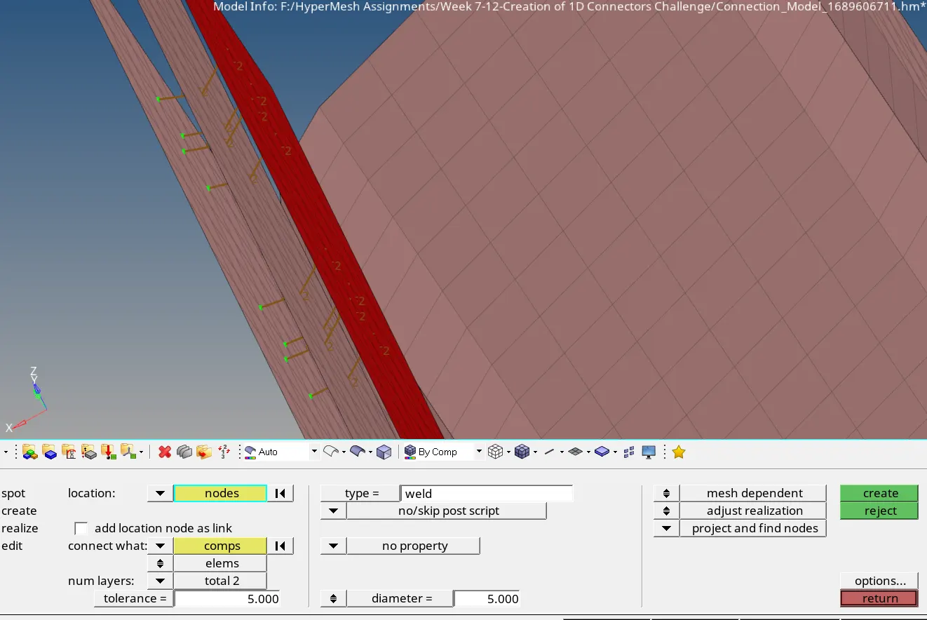
Figure 8: Showing Spot weld with 2 layer and 5 mm diameter
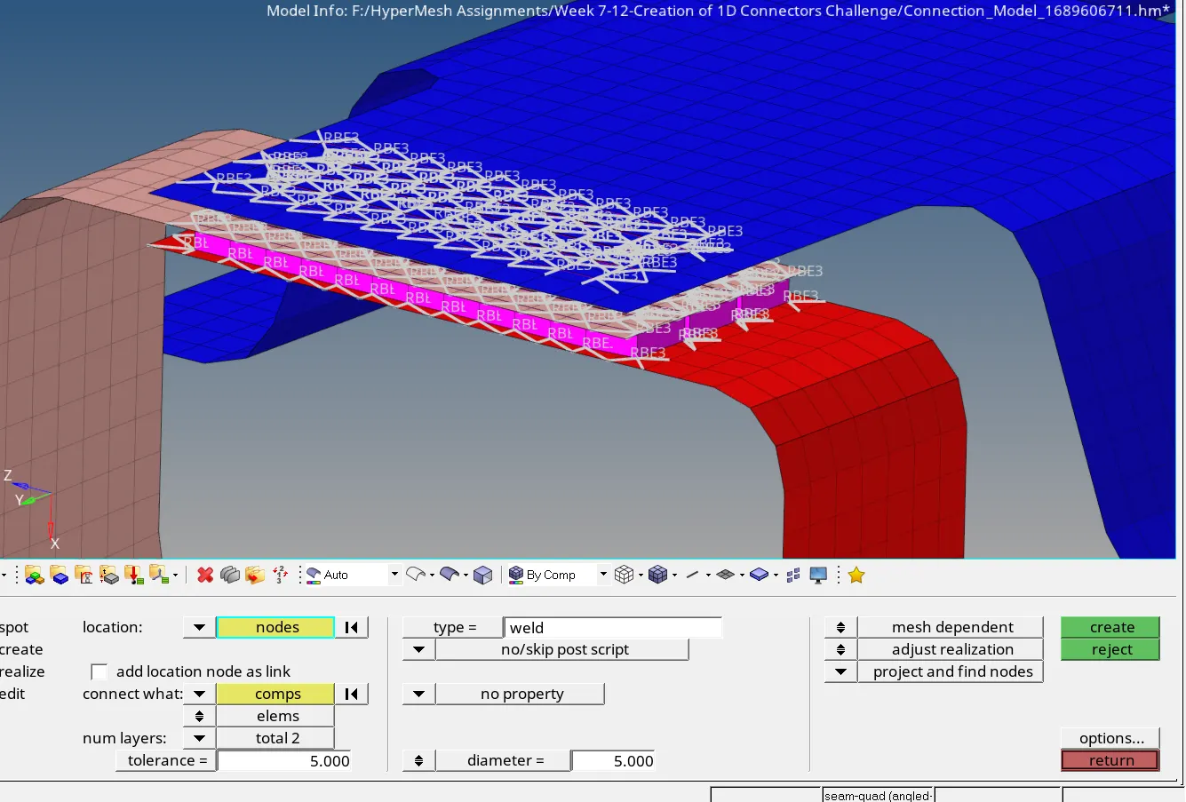
Figure 9: Showing elements with Hexa (adhesive)
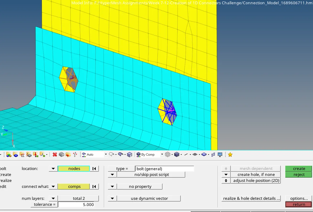
Figure 10: Showing Bolt Connector
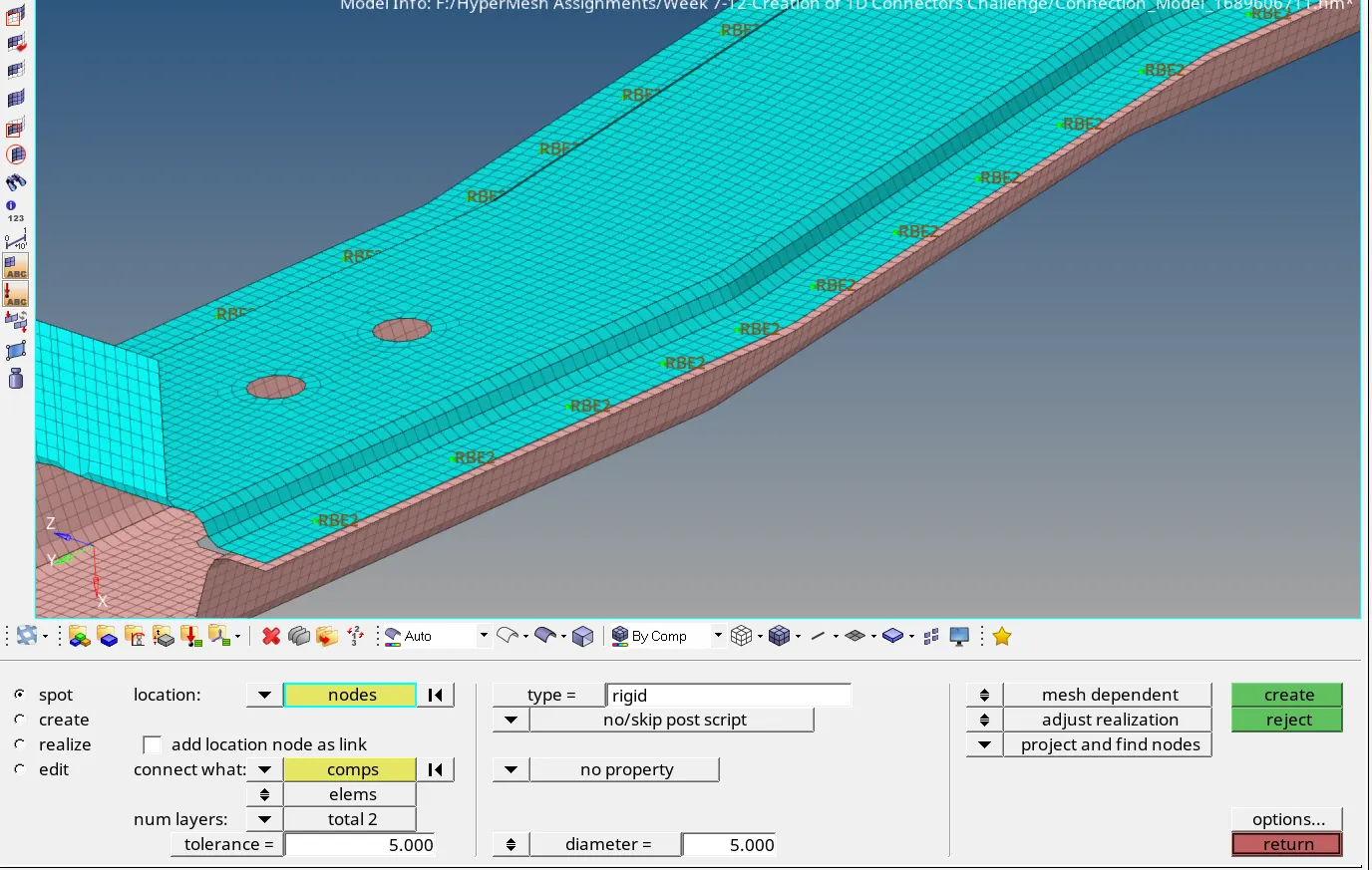
Figure 11: Spot weld with Rigid elements
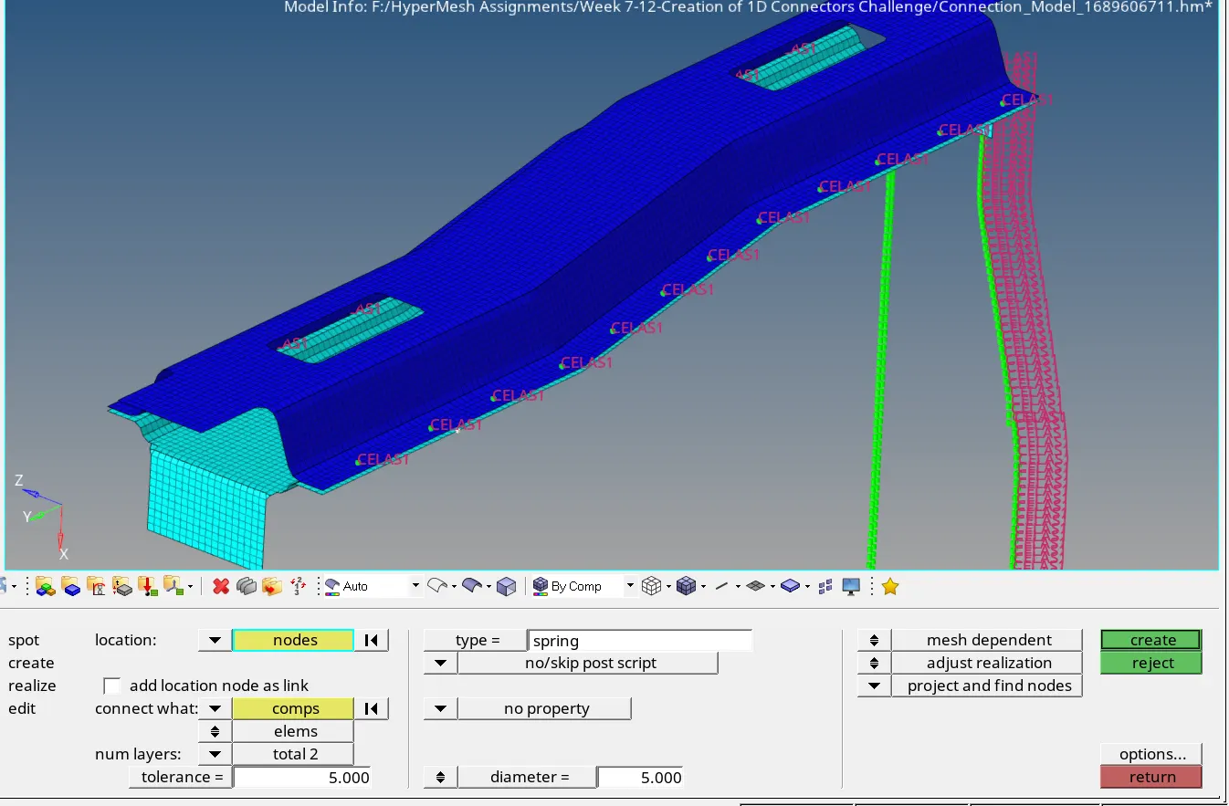
Figure 12: Spot weld with spring elements
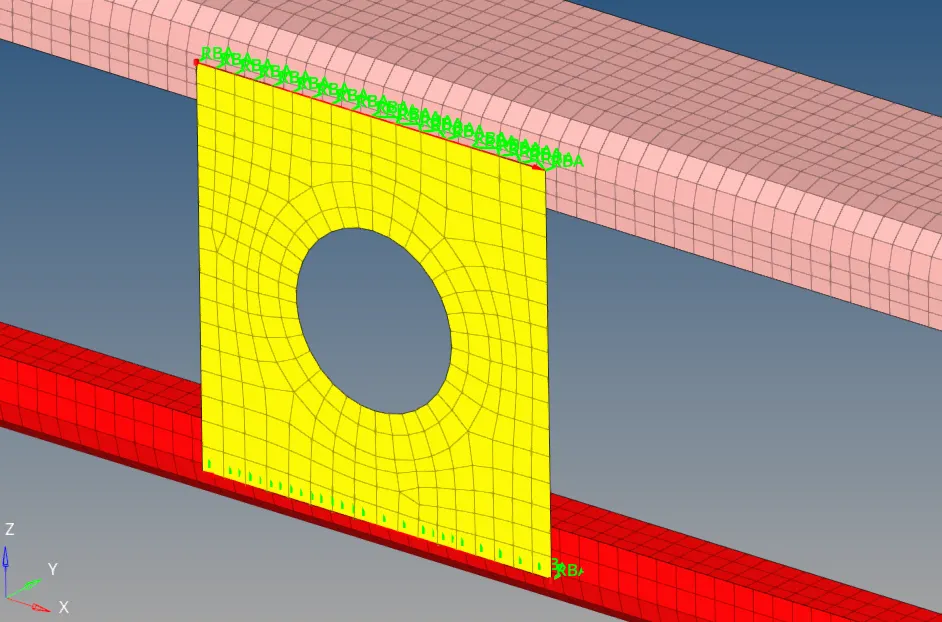
Figure 13: Showing image of Reinf plate coonected using rigiid bar elements.
As shown in the above images, all the parts of the assembly are joined together using elements specified. The final image of the model is shown below-
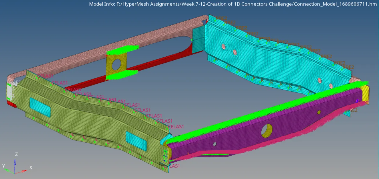
Figure 14: Showing image of full model.