Week-6 : Turbocharger Modelling
1. List down different TC and Locate examples from GT
->
i. Fixed Geometry Turbo (FGT) - it is basic and simplest type of TC (turbo charger) which is in use and does't have any waste gate or variable geometry or duel scroll. Being simplest construction it's cheapest but at same time it's working rage is also comparitively limited than WG and VG. GT example : CompressorTurbine-Flow
ii. Waste gate Turbo (WGT) - this type of TC has a pressure relive provision on it by which some of the exhaust gas upstream TC is directly bypassed into TC downstream which reduce flow through TC and limit it's speed and pressure. Such bypass provision is called waste gate. this is mainly to safeguard TC from structural damage due to excess velocity at high engine speeds as well as sometimes control TC output as per requirment. GT example : Diesel_WGController
iii. Variable Geometry Turbo (VGT) - At low engine speeds, low flow rate in FGT tends to produce low RPM and hence low boost and that too with slugish response (i.e. higher turbo lag). If one can manage to guide flow such that turbo will reach higher RPM can solve a problem. This is what exactly VGT does. Also at higher engine speeds, higher exhaust flow rate lead to increase turbo RPM beyond it's maximum saferty limit. At such instance flow must be guided such that RPM will not cross safety limits. This can also be done using VGT. Ultimately VGT allows turbo to produce better boost at lower RPM and control turbo speed at higher RPM there by allowing turbo to work with better efficiency and safety in much broader range of Engine RPM. VGT has extra flow guiding flaps construction, made before TC blades. This controls, how flow will go on blades and thereby how much output/efficiency a TC can generate at various operating conditions. As VGT needs additional moving parts in TC which makes TC construction much more complicated and hence cost of VGT is very high. Also we need to have additional electronic and ECU provisions to integrate VGT which further add up to cost and complications. VGT is more worth to use when we have wide rage of Engine RPM's to work on and engine permormce is important than cost, which is generally a case in racing cars or high end high cost vehicles. Additional cost and complication make VGT not so generally used technology in cost sensitive markets or segments. GT example : Diesel_4cyl_DIPulse_InjRateMap
iv. Twin Scroll Turbo (TST) - is used when one has more than 4 cylinders and want to segregate blow by pulse of cylinders. Being more than 4 cylinders it is very much clear that there will be overlapping pulses which can be handled more efficiently with twin scroll and also longevity of turbo can be increased. Twin scroll turbo can be replaced by multiple single scroll turbo. In terms of working range, cost and complication, we can place VGT, TST, WGT and FGT in decending order. GT example : 07_Turbocharging/Turbo_Step5-final
v. Parallel construction : it allows using multiple (generally dual) and comparitively smaller TC (connected to different cylinders) instead of single big TC. In parallel contruction along with multiple turbo, single or multiple compressors can be used. GT example : Gasoline/3pt4L-V6-TwinTurbo-GDI
vi. Series construction : it allows to extract more kinetic energy out of exhaust flow by adding multiple turbo one after another. Turbo into which exhaust gas enter first is called high pressure turbo and respective compressor called high pressure compressor. Second turbo into which exhaust gas enters after high pressure turbo is called low pressure turbo and respective compressor as low pressure compressor. If second tubo is supplying power to engine instead of low pressure compressor, then its called power turbo. GT example : Diesel_6cyl_TC
2. Explore Tutorial no. 6 and 7
In tutorial no. 6 (i.e. 6cylDI-final), instead of modeling compressor with map, just boost pressure at compressor outlet is inputed. Also instead of modeling turbocharger with map, turbo upstream back pressure is inputed. This is segregated and simplified approach. As there are two seperate outlets of exhaust gas after runner indicates that this is twin scroll turbine. Pressure at compressor outlet will always be slightly lessor than turbo inlet due to increased pressure and temperature during combustion.
In tutorial no. 7 (i.e. Turbo_Step5-final), both compressor and turbine are modeled using thier respective map and referance properties need to be mentioned. Compressor map include corrected speed (RPM) vs mass flow rate, pressure ratio and efficiency. RPM correction is done based on referance properties such as temperature, gas constant and specific heats. Turbo map is generally as per SAE standerds where RPM and Massflow rate is changed to RPM reduced and Mass flow Rate reduced. RPM reduced is derived by substituting actual RPM by turbo inlet total temperature. Mass flow rate reduced is derived by multiplying actual Mass flow rate by turbo inlet total temperature and substituting by turbo inlet total pressure. Hence turbo map includes RPM reduced vs mass flow rate reduced, pressure ratio and efficiency. For turbo, maximum pressure ratio and maximum speed reduced also need to be defined to esure avoiding irrelevant extrapolation and avaoiding breaching safety limits.
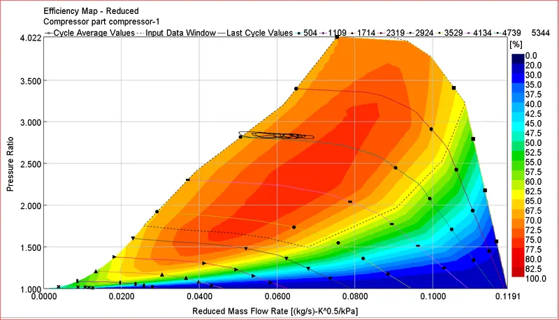
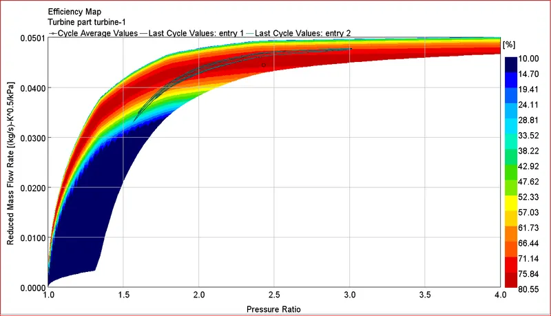
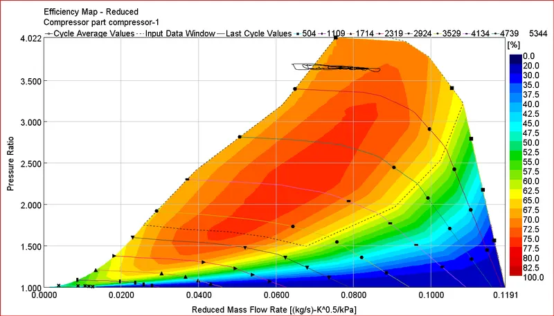
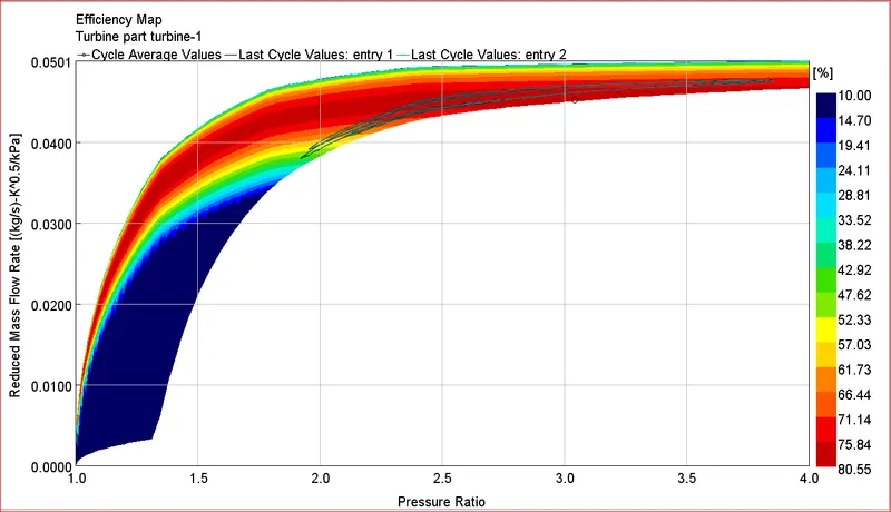
3. Plot Operating Points on Compressor and Turbine Map
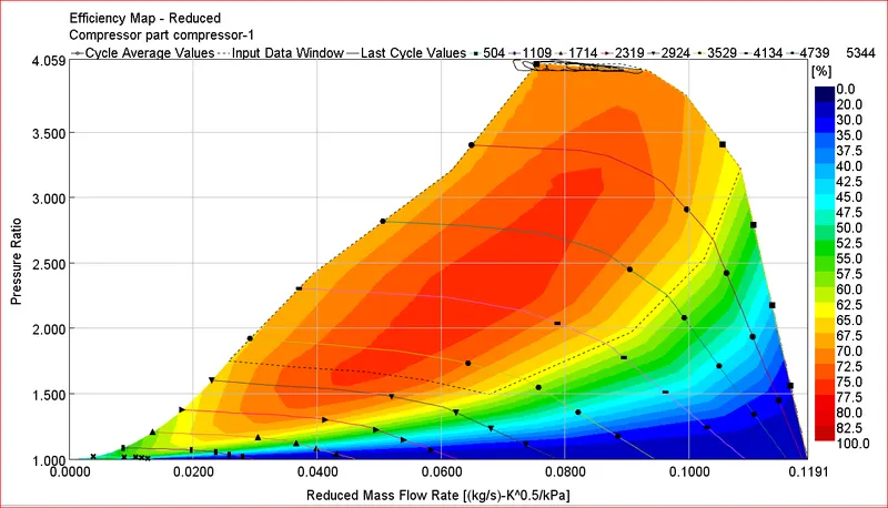
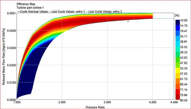
4. In which application Variable Geometry Turbine is beneficial?
When engine runs on vast range of RPM. At low engine speeds, low flow rate in FGT (fixed geometry turbine) tends to produce low RPM and hence low boost and that too with slugish response (i.e. higher turbo lag). Whereas at higher engine speeds, higher exhaust flow rate can lead to increase turbo RPM beyond it's maximum saferty limit. Smaller turbo can resolve low engine RPM issue but not suitable for high RPM case whereas bigger turbo can solve high engine RPM issue but is not suitable for low RPM. Best case situation is when one can manage to guide flow such that at low engine RPM, turbo can attain higher RPM and at higher engine RPM, turbo RPM will not exceed safety limits. This is where VGT can be used. Ultimately VGT allows turbo to produce better boost at lower RPM and control turbo speed at higher RPM there by allowing turbo to work with better efficiency and safety in much broader range of Engine RPM. Due to this characteristics, VGT technology also allows turbo to be more compact. But As VGT needs additional moving parts in TC which makes TC construction much more complicated and hence cost of VGT is high. Also we need to have additional electronic and ECU provisions to integrate VGT which further add up to cost and complications. VGT is benificial in applications where Engine RPM range is wide, engine performance is important than final product cost, where parts need to be compact due to space/packaging constrains. Such applications can be racing cars, delux/luxury cars and very specialized application equipments such as mining equipments.
5. Explore example- Diesel VGT EGR and understand the modeling part
In given example, Compressor map include speed (RPM) vs mass flow rate, pressure ratio and efficiency. Being VGT, there are turbo maps with respect to rack position. Each Turbo map includes RPM reduced vs mass flow rate reduced, pressure ratio and efficiency. To achieve target BMEP at given engine speed (and other defined parameters like Rail pressure etc.), to maintain AFR above 17 (as defined in setup), fuel mass and air mass is calculated and demanded through ECU signal. Now to get required amount of fresh air, desired compressor RPM to be meet as per compressor map. Now to meet desired Compressor rpm same RPM is to be meet in turbo. For that desired turbo RPM with available exhaust flow (dependent on Engine RPM/speed) rack position is tunned by ECU.