Week-6 : Turbocharger Modelling
Q:-List down different TC and locate examples from GT Power
Ans:- Turbocharger is used to increase boost Pressure of air intering into Cylinder. It increase air density of inlet air and more air provided for combustion.It increase 15% of Power output of Engine There are three type of Turbocharger configuration as given below
(1) Fixed Geometry Turbocharger
(2) Wastegate Turbocharger
(3) variable geometry Turbocharger
(4) Electronic control Turbocharger
(1) Fixed Geometry Turbocharger
Boost Pressure of Turbocharger change with changing flow velocity of Exhaust gas.So at low and High exhaust gas velocity Turbocharger Choke and Surge respectively and does not Provide enough Boost pressure and reduce Turbocharger efficiency.
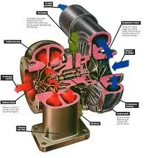
Below are example of Turbocharger (fixed Geometry ) GT Power
(2) Wastegate Turbocharger
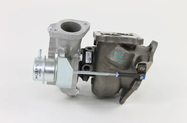
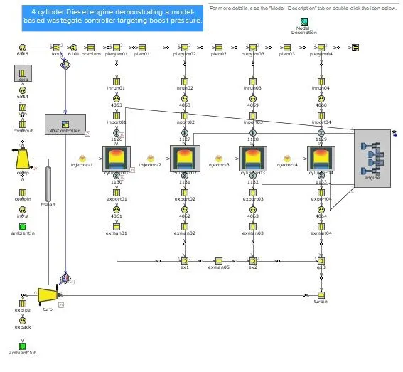
Boost Pressure of Turbocharger is control with wastegate which is pneumatically activated at fixed Pressure. When compressor Speed increase beyond predefined speed ,the wastegate will open and bipass Exhaust Gases to Reduce Speed of Compressor. This Turbocharger help to maintain fixed Boost Pressure at higher Engine Speed.
Below are example of Turbocharger Wastegate GT Power
(3) variable geometry Turbocharger
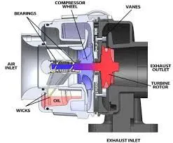
Variable Geometry Turbocharger Provide Fixed boost pressure at variable Engine speed. Velocity of Exhaust entering into Turbine is control with variable Blade therefore provide fixed boost pressure even with changing Exhaust gas flow rate.
Below are example of Turbocharger Variable geometry GT Power
(4) Electronic control Turbocharger
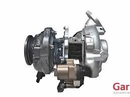
Boost Pressure and speed of Turbocharger is electronically control with ECU. ECU according to Engine Speed Provide signal to E-Turbocharger and control Speed of Compressor.
Q2:-Explore tutorial number 6 and 7
Tutorial 6:-
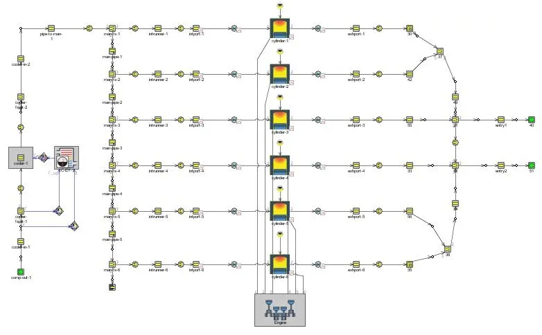
Below are example of fixed geometry Turbocharge. The Inlet Air Pressure is set at 2 bar which show compressor outlet pressure of Turbocharger and there is two Exhaust outlet showing Twin scroll Turbine.
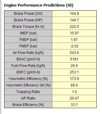
Engine Performance Parameter
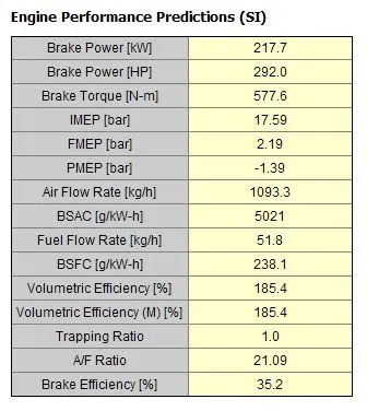
Power Of Engine is increased due to Turbocharger
Tutorial 7
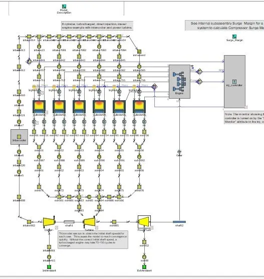
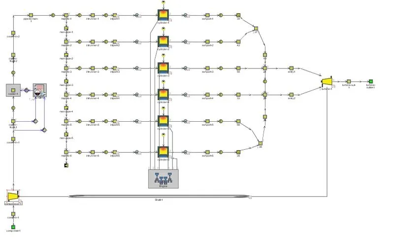
This Tutorial represent Air at ambient pressure and Temperature enter into compressor which compress Air and increase temperature and Pressure. High temperature air passes through intercooler and density of air increase so more air enter into Combustion chamber. Exhasut from manifold Enter into twin Scroll Turbine which doing work on Turbine and emit into atmosphere.
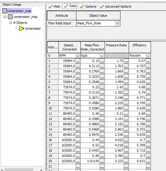
Compressor Data are given Below
Mass flow ,Pressure Ratio, Speed and efficiency
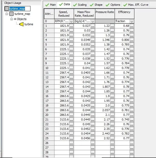
Turbine Data are given Below
Mass flow ,Pressure Ratio, Speed and efficiency
Q:-Plot operating points on compressor and turbine maps
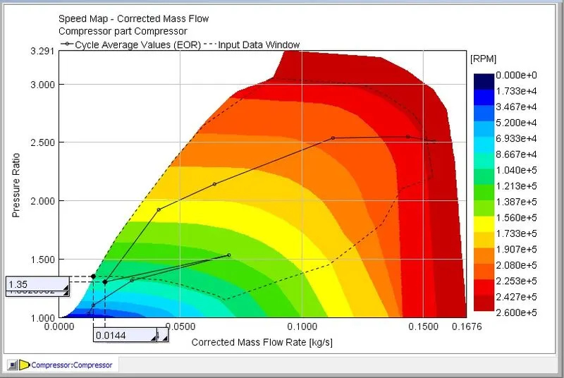
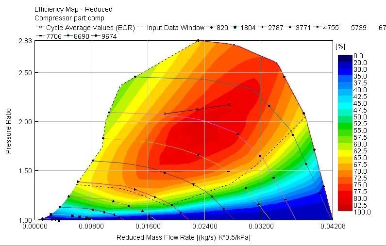
On Compressor graph Mass flow rate of air is on X axis and pressure ratio is on Y axis.Curve line along X axis are Speed line and Curve line along Y axis are Efficiency lines. As shown Below three Points represent in best Efficiency range.so turbocharger should run in best efficiency range on Graph
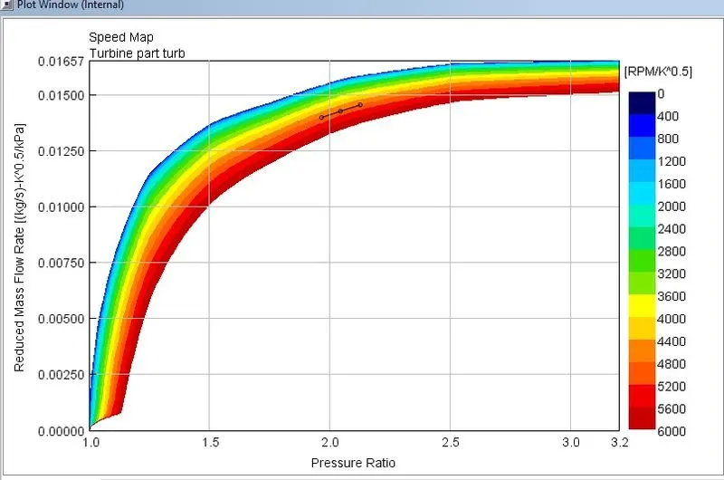
For Turbine Graph below graph is important.In this graph turbine run in best range.
Q:-In which application Variable Geometry Turbine is beneficial?
VGT is mostly used in comercial Vehicle which overcome Turbo lagging Problems.So when vehicle start it run at lower RPM,VGT by changing Position of blade provide design boost Pressure to Engine and doesn't lag.Therefore it is mostly used into comercial vehicles like cars,Buses and Trucks.It also beneficial at higher altitude and give best results.
Q:-Explore example- Diesel VGT EGR and understand the modeling part.
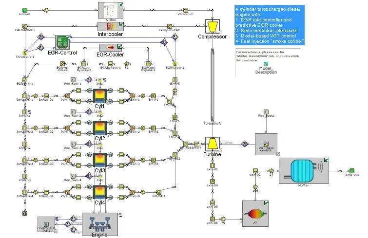
Below layout represents VGT with EGR,air enter at ambient conditions passes through air box and goes into comprssor which run through Shat on which turbine is mounted.Turbine runs through flow velocity of Exhaust.Compressed air passes through Intercooler which decrease temperature of air to increase density and goes into inlet manifold.Exhaust gas from cylinder is cooled into EGR cooler and mixing of Exhaust into inlet air is controlled by EGR valve which is butterfly control.
There is VGT rack controller which control blade positions and vary speed of Turbine and hence boost Pressure and Target BMEP into cylinder.
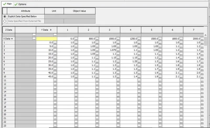
VGT RACK CONTROL
It represent RLT graph in which X data respresent Engine Speed and Y data represent fuel injection Quantity.Rest table represent boost pressure and blade opening is control according to it.
Engine performance parameter are given below
Brake Power= 140.7 HP
BSFC= 253.1 g/kwhr
Air flow rate= 26.6 kg/hr
Compressor Map
Compressor map Respresents that at different Engine speed there is change in pressure ratio according to required BMEP.