Week 4: Project - Steady state simulation of flow over a throttle body
Problem:- Steady state simulation for flow over throttle Body when it is fully open and show pressure and velocity graphs, glyph and stream line motion.
Solution:- Set up case of throttle valve fully open and set initial conditions as follows
Species:- Air flow over Throttle valve
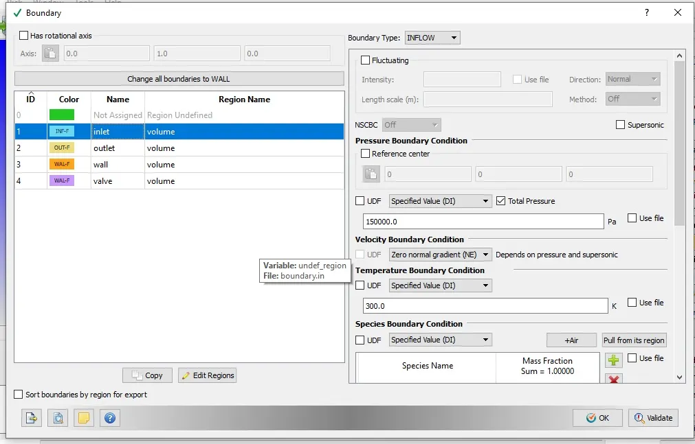
Boundry conditions:- Inlet Pressure 1.5 bar
Temperature boundry condition at inlet 300K
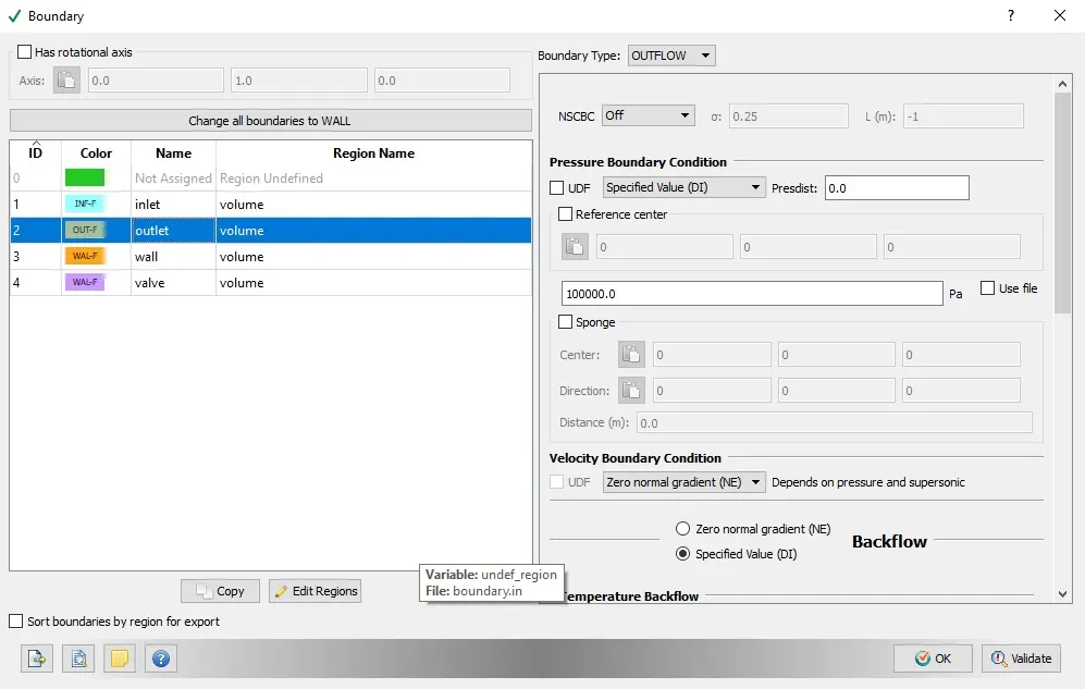
Boundry conditions:- Outlet Pressure 1.0 bar
Temperature Backflow at inlet 300K
Simulation Time parameter
Set intial Cycle start :-0 cycle
End Cycle time:- 25000Cycle
Intial Region Condition
Set Intial region condition at Temperature 300k and at Atmospheric Pressure 101325.0 Pa
Grid size and Fixed embedding
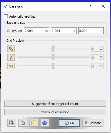
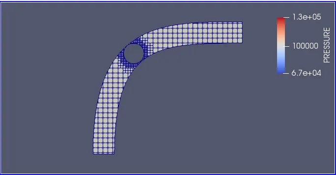
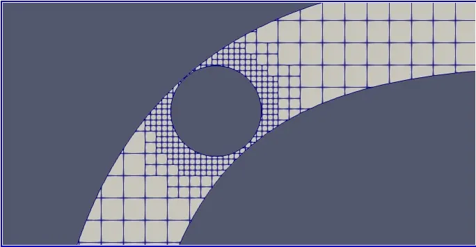
Intial grid size set at dx=0.004 dy=0.004 and dz=0.004 and use fixed embedding option to refine mesh at throttle valve to get more accurate results at throttle body.Set scale value at 2 and embaded layers at 3. It will reduce size mesh near throttle surface in half in first embedding and again half in next layer of embedding and remain continoues for 3 embedding layer.
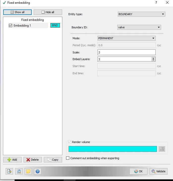
Export file and run through cygwin and then use converge interface to convert output files into 3D post.out file. These file will open in paraview platform. Converge platform will also used to create line Graphs.
Results
Mesh size
Paraview platform will help in showning mesh pattern of throttle valve challange. As shown in fig below Embedded mesh help to refine mesh structure near throttle valve surface. As surface width at this section is very less so to get accurate result we should have enough mesh count on this section.
Pressure Profile
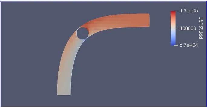
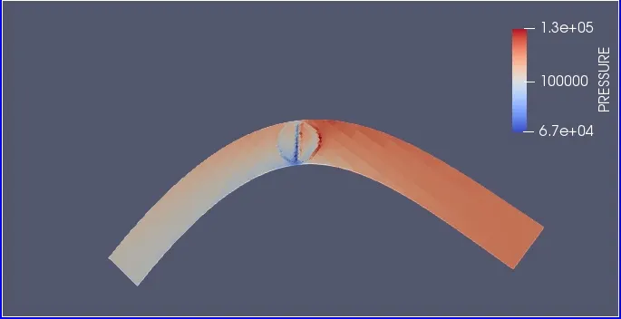
Pressure Profile is shown in fig Below.
Velocity Profile
velocity Profile shown in fig below.
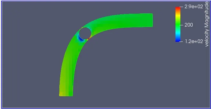
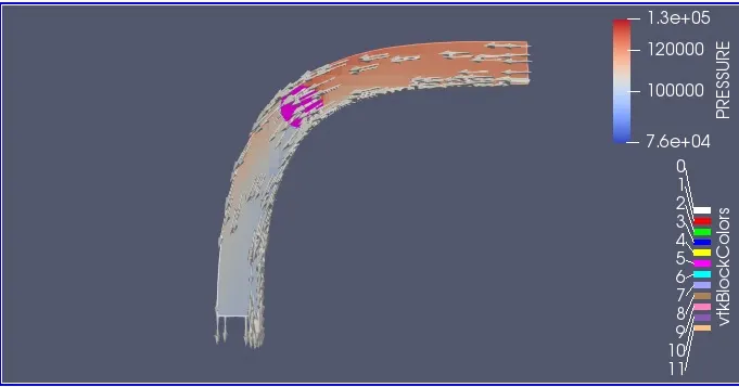
Glyph Profile and Profile over throttle valve
glyph Profile show that air flow is ok and second graph show that Pressure at throttle valve increase at inlet boundry and seperation of flow occour at valve ,so blue color of valve show that pressure is drop on other side.
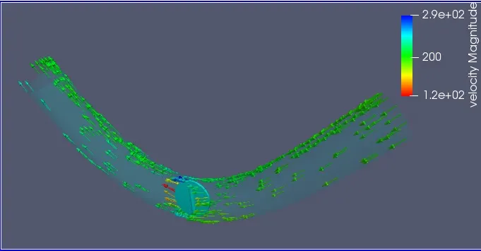
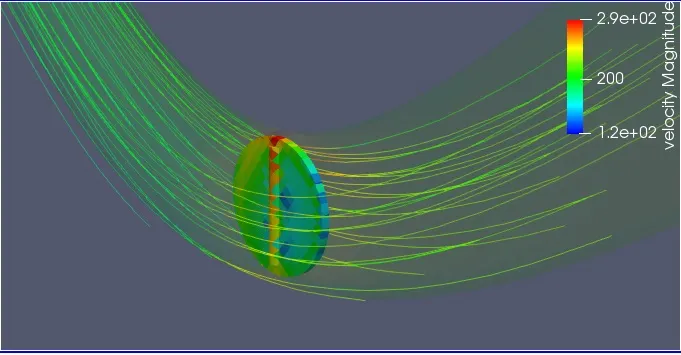
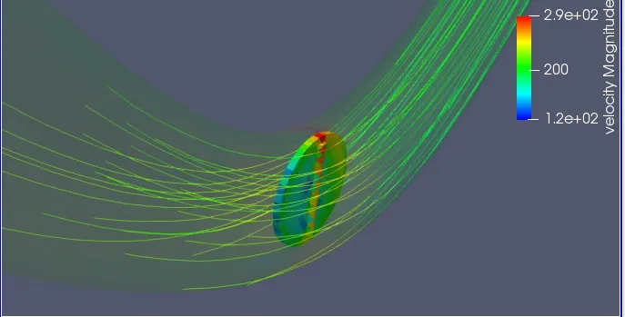
Streamline flow
Paraview help in showing streamline flow and streamline graphs are shown Below. It also show the same results that due to seperation velocity will decrease after passing over throttle body.
Line Plots
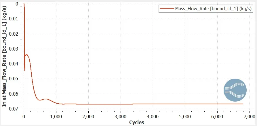
Mass flow rate(Inlet boundry)
Mass flow rate at inlet boundry and converged to value 0.066 Kg/s
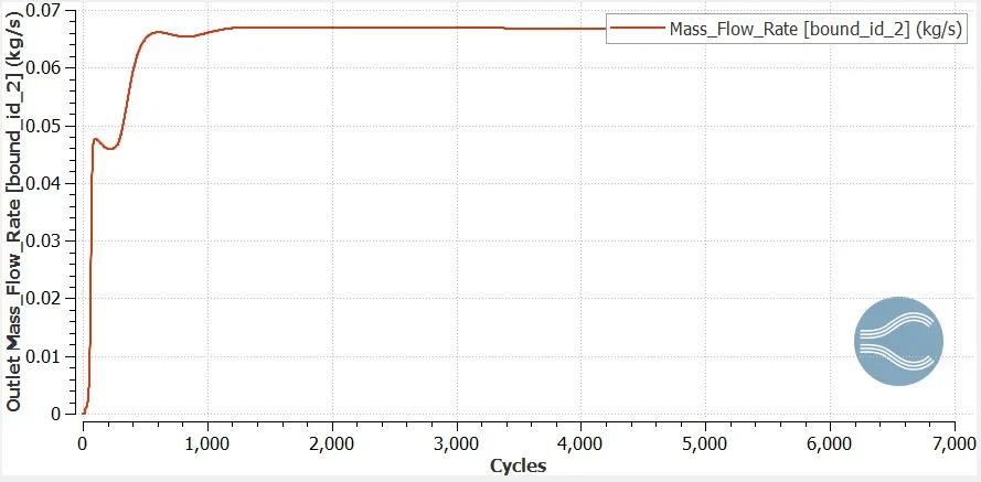
Mass flow rate(Outlet boundry)
Mass flow rate at outlet Boundry is converged at 4000 cyl and attain value of 0.66 kg/s.
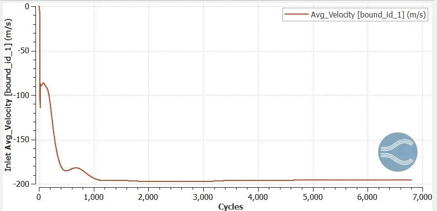
Velocity Line Graph (Inlet Boundry)
Velocity at inlet boundry converge at 5000 cyl and attain constant value of 195.8 m/s
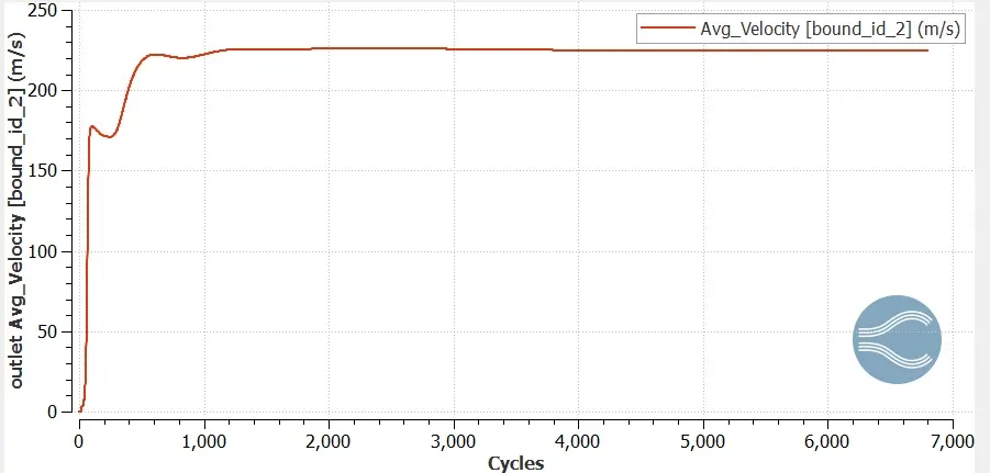
Velocity Line Graph (Outlet Boundry)
Velocity at inlet boundry converge at 5000 cyl and attain constant value of 225 m/s