Week-6 : Turbocharger Modelling
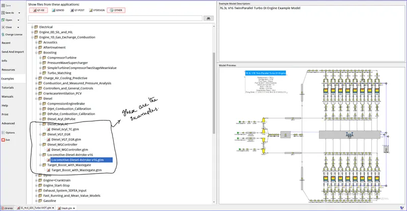
List down different TC and locate examples from GT Power
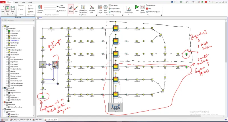
Tutorial 6:
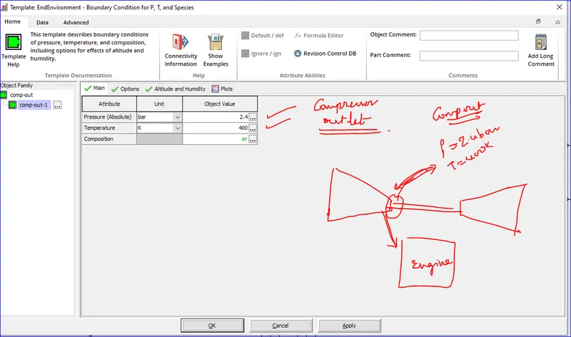
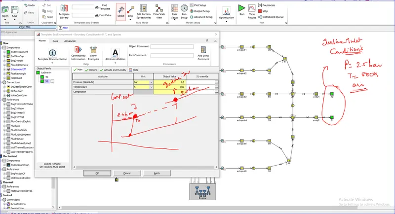
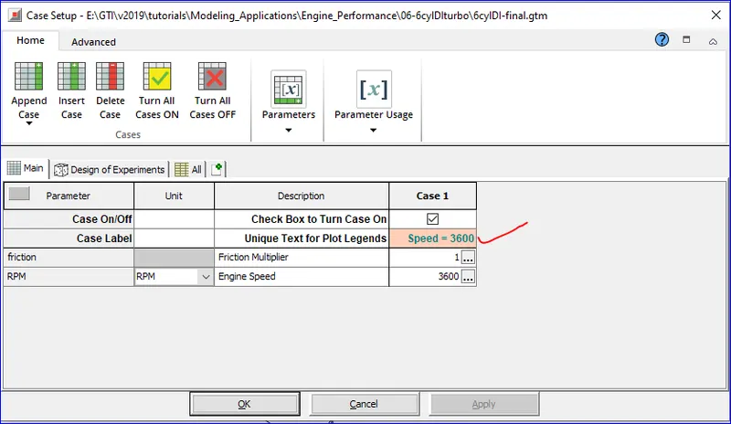
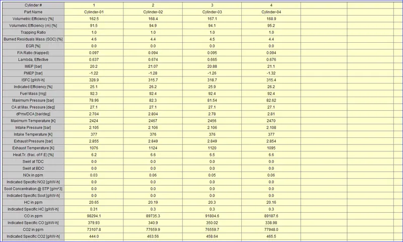
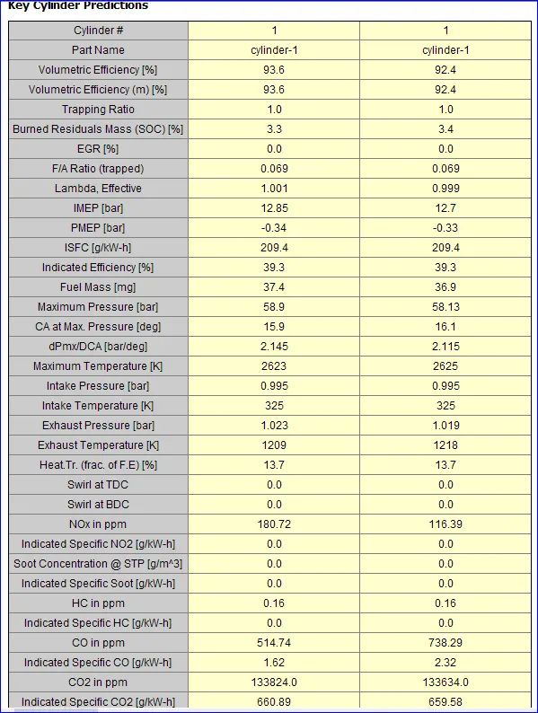
The test case is run and the following are the results:
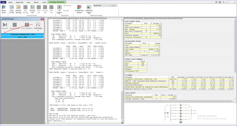

Tutorial 09: Making from base model:
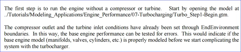
The following things needs to be checked for the correctness:
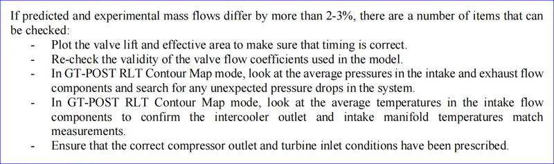
For the purpose of the tutorial, it will be assumed that the predicted mass flow matches experimental measured mass flow. This step tells the user that the base engine model is accurate in the prediction of engine mass flow.
Model Engine with No Turbine (only Compressor)
The second step is to add the compressor to the engine, while keeping the turbine inlet boundary modeled with EndEnvironment parts.
- This will allow us to independently study the compressor performance before complicating the engine system with the turbine. Continue with Turbo_Step1-Begin.gtm and save the current project as Turbo_Step2.gtm.
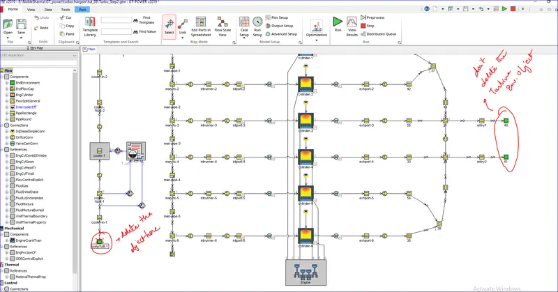
- Start by deleting the EndEnvironment part that represents the compressor outlet conditions.
-
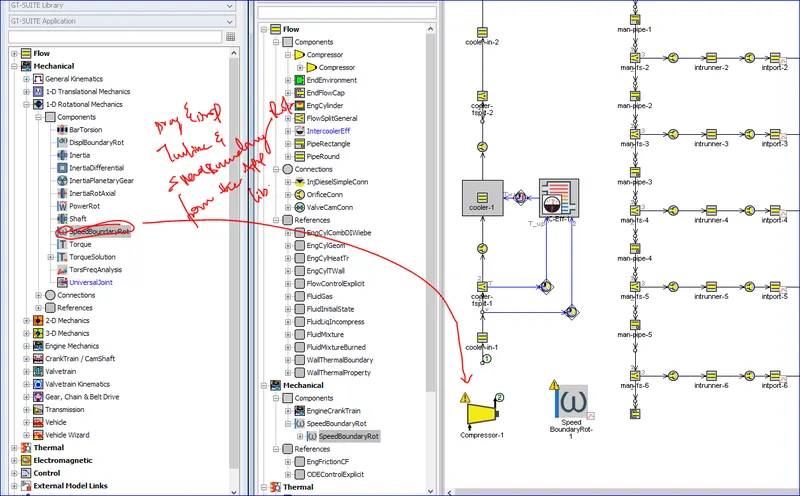
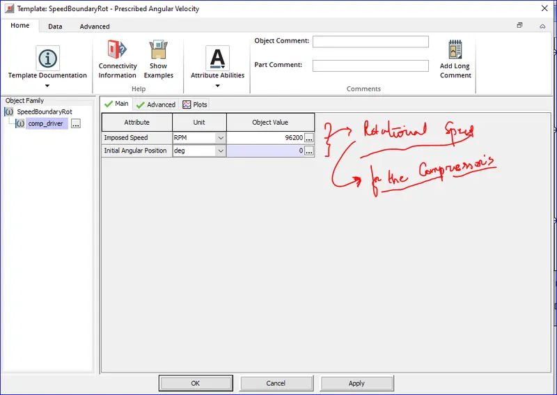
Next, open the template library and copy the 'Compressor' template from the Flow -> Turbines, Pumps and Compressors folder and 'SpeedBoundaryRot' template from the Mechanical -> 1-D Rotational Mechanics folder into the project library.
-
Double-click on the 'Compressor' template and start filling in the object values below.
-
For compressors, turbocharger suppliers commonly measure total inlet pressure and total outlet pressure.
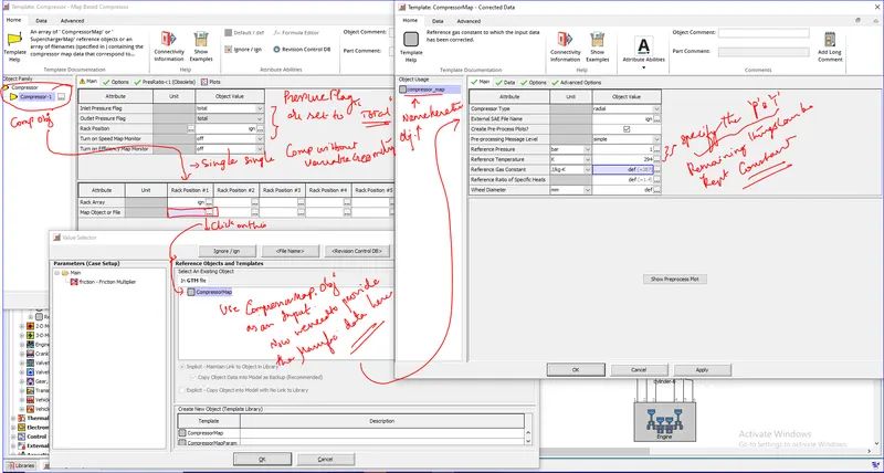
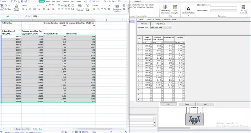
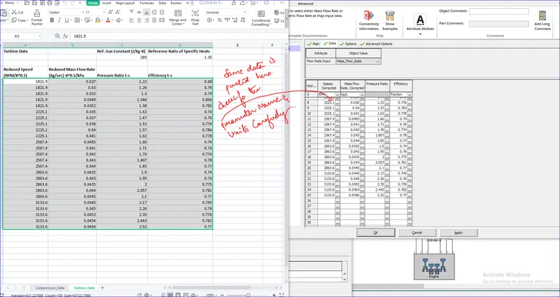
- Double click on the compressor map object and select the CompressorMap reference template. The input data needed for this object is in an Excel file located at ../Tutorials/Modeling_Applications/Engine_Performance/07-Turbocharging.
- Copy this data and paste it in the Data tag and make sure that the mass flow rate option is used rather than volumetric flow rate in teh flow rate input attribute.

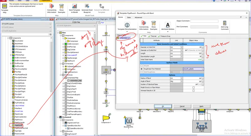
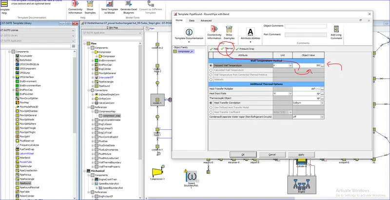
- Next, create a new object from the 'PipeRound' template to represent the compressor inlet pipe. Fill in the attributes with the following values:
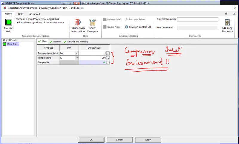
- Create a new 'EndEnvironment' object called "comp-inlet". This object will represent the ambient conditions entering the compressor. Therefore, set the pressure attribute to 1 bar, the temperature attribute to 298 K, and the Composition attribute to air.
Results:
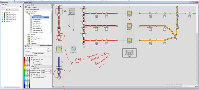
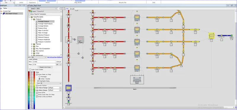
Case RLT plots:
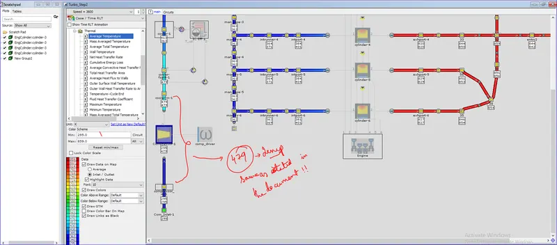
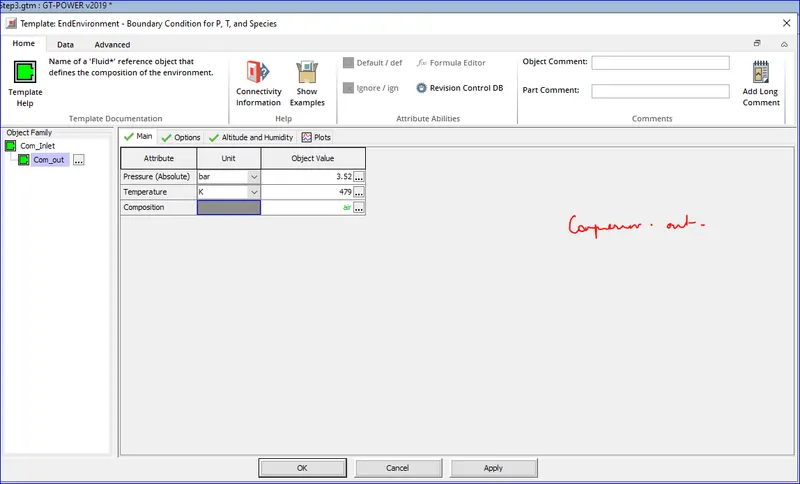
Finally, take a note of the outlet pressure and temperature of the compressor, it will be needed in the next step. You should see a pressure of 3.52 bar and a temperature of 479 K.
Step 3:
- Next step is same as the previous one. We need to just add an turbine and remove the compressor. In place of an compressor replace it with an end environment of 3.52 bar and 479K.
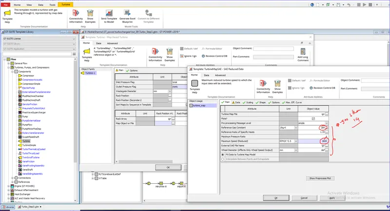
- Copy the 'Turbine' template from the template library into the project library. Double-click on the 'Turbine' template and create an object with the following values.
- Note that the inlet and outlet pressure flag attributes should be set according to how the turbine performance data was measured (information that is provided by turbocharger supplier). For turbines, turbocharger suppliers commonly measure total inlet pressure and static outlet pressure.
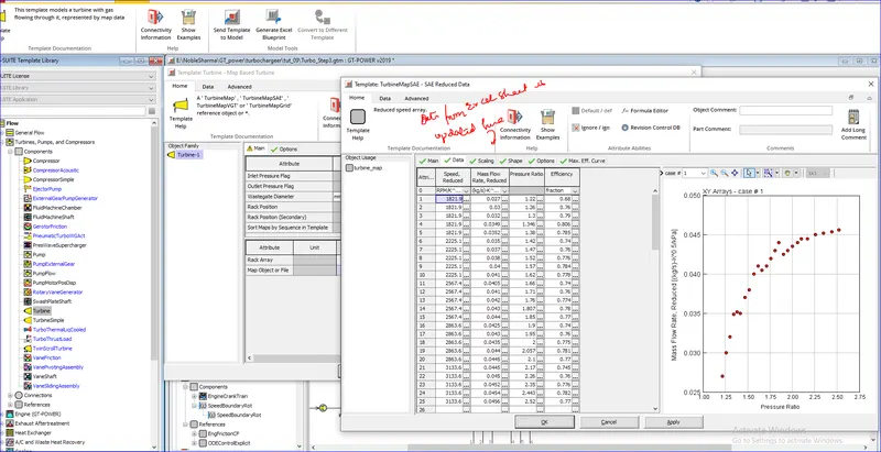
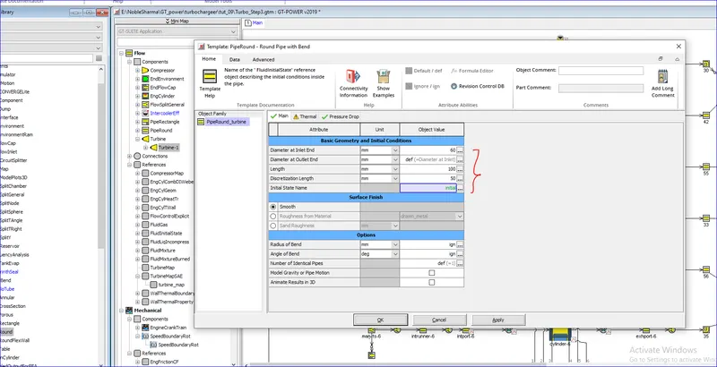
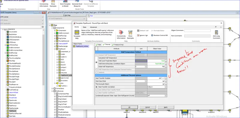
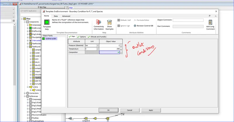
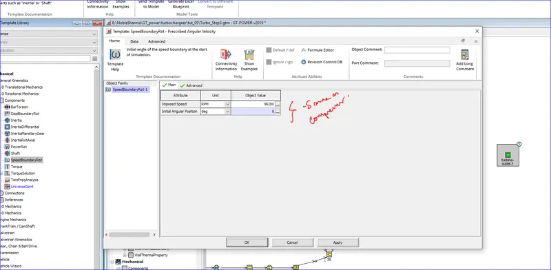
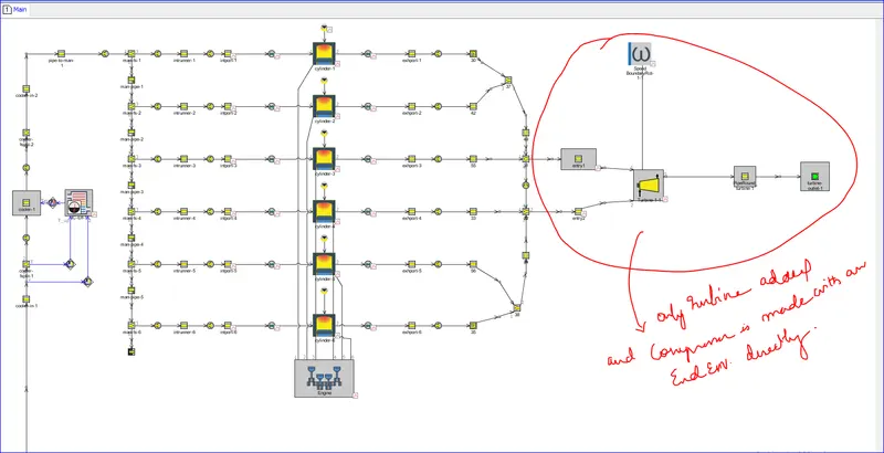
Results:
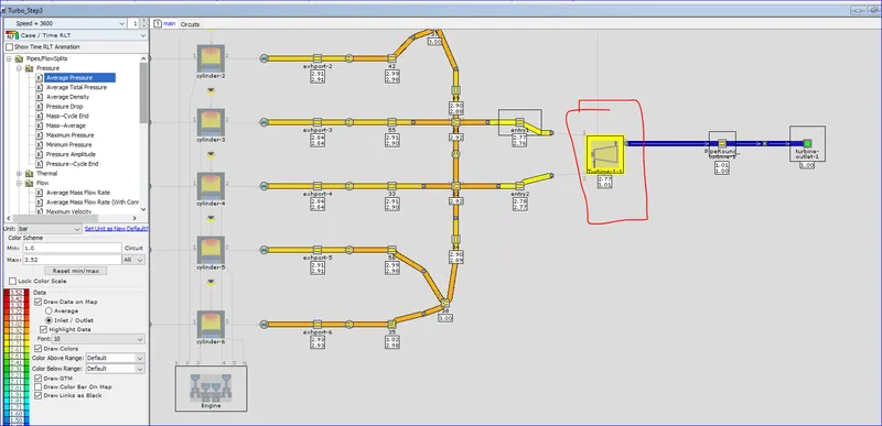
- Finally, run the model and once again check the predicted engine mass flow rate in GT-POST. This step is a check on the turbine map. Just as in the previous step, adjust the Mass Multiplier attribute in the "turbine" object.
Step 4
calibrate the compressor and turbine power. Continue with Turbo_Step3.gtm or open Turbo_Step3-final.gtm from the same directory. Save the current project as Turbo_Step4.gtm