Week 6-Meshing of Hood Challenge
Week 6-Meshing of Hood Challenge
Objective
To create a 2D mesh for the given Hood model in Hypermesh.
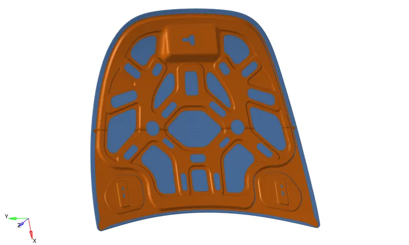
CAD model image
Procedure
The completion of the model was done in the following process:
- Extracting mid-surface from all the components
- Cleaning up the geometry
- Creation of 2D shell mesh
- Assigning thickness to the elements
i. Extracting mid-surface from all the components
The given hood model is a sheet metal model and therefore has uniform thickness.
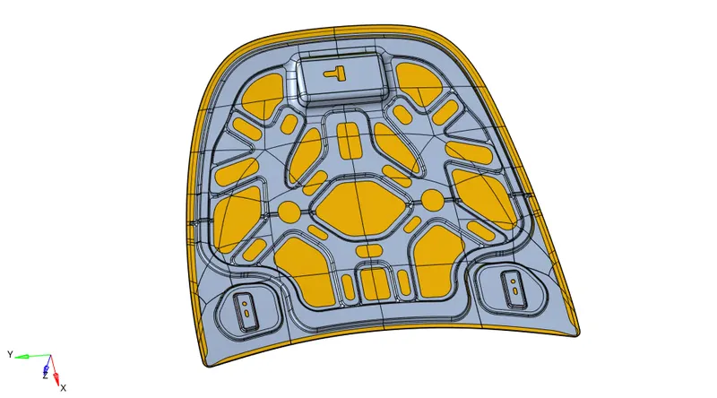
The mid-surface was extracted using Geom`rarr`surface edit`rarr`offset option.
The hinge and latch components had a thickness of 1.2 units and the thickness of the outer and inner extract components of the hood was 0.75 units.
One face of every component was offset to half the thickness of the component.
The mid-surface of the outer extract component near the hemming region, was obtained by creating a mid-line between the hem. The mid-line was projected onto the mid-surface and the other two lines were toggled. This was done to ensure that the elements do not fail the required minimum element length.
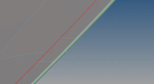
These extracted mid-surfaces were organized into separate component cards.
ii. Cleaning up the geometry
The surface was cleaned up to ensure that the elements meet the quality criteria and have a good flow.
In areas having two shared edges close together, the elements would fail in the minimum length criteria and hence one of the lines were toggled off or a new mid-line was created and the other two were toggled.
In the outer extract component, the lines were toggled entirely since they would affect the flow of mesh. New lines were made on the surface to maximize good flow of elements.
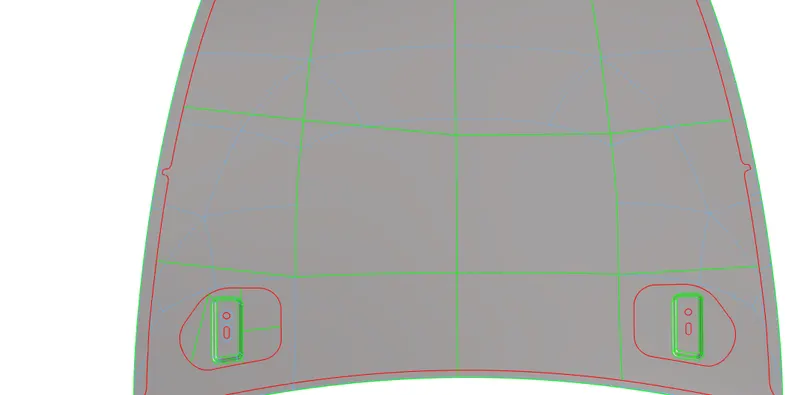
On the inner extract component, the areas having the fillets and small corners were checked and cleared up. Care was taken to ensure that the geometry and structure remained intact while toggling and creating lines.
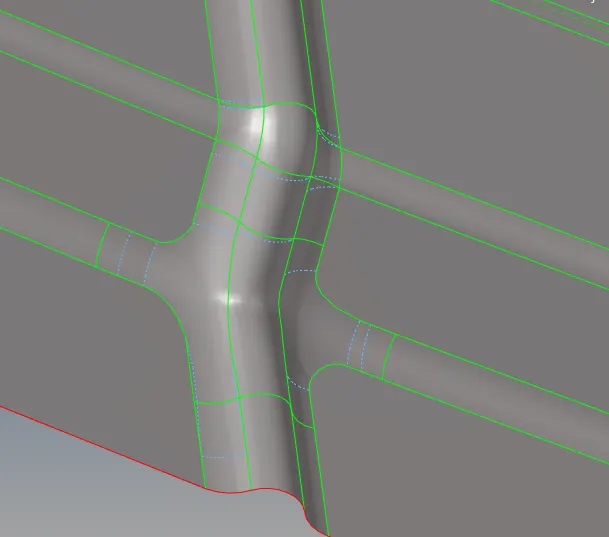
At the corner fillet, a new center line was made to control the number of elements and the unnecessary lines were removed.
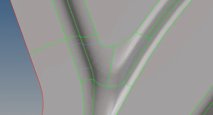
New lines were created all over the surface to split them and make the automatic mesh generation effective.
iii. Creation of 2D shell mesh
Mesh generation
After the components' geometry have been cleaned up, the mesh was created on the surface.
To create a 2D shell mesh, the 2D`rarr`automesh`rarr`surfs option was used.
The mesh density was controlled on the edges to create a balance between good mesh density and tria concentration.
Some tweaks were also made on the mesh style wherever necessary to obtain a good automatic mesh generation.
The biasing was adjusted to remove opposing trias, to straighten the mesh when it wasn't straight.
Mesh flow
After the mesh was automatically generated, the elems option was used to select smaller groups of elements in order for the mesh algorithm to work better and create a better mesh removing rotating quads and pattern trias.
Apart from this, the cleanup tools such as swap edge, drag tria element, combine tria elements were used to remove opposing trias and to drag them out the edge.
The smooth option was used to smoothen the elements to create a mesh that is even in spacing and without any abrupt and jagged edges.
Connectivity
The Tool`rarr`edges`rarr`find edges option was used to check for unconnected elements. This is crucial in mesh generation as an unconnected mesh causes errors while processing.
The elements that weren't connected were connected using the 2D`rarr`replace option to connect nodes.
Duplicate elements were deleted and new elements were created wherever necessary using the edit element`rarr`create.
Checking for quality
The given element criteria was entered into the Criteria file settings window.
When the color mode view is changed to show element quality, the elements which fail the criteria were highlighted, and they can be corrected using elem cleanup option, However this option tends to make the nodes stray out of the geometry lines and so the failed elements were re-meshed.
The 2D`rarr`quality index`rarr`QI settings option was used for more specific corrections. The failed elements were saved and retrieved in the mask option. The isolated elements were then corrected.
This was continued until zero failed elements remained.
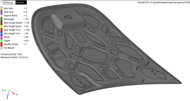
Symmetrical component
The inner extract is a symmetrical geometry and hence one side was meshed and the mesh was mirrored to the other side using the Tool`rarr`reflect option. This was done to save time.
After mirroring the elements, the edges are checked and the mesh is stitched together using the equivalence option.
iv. Assigning thickness to the elements
2D shell mesh is used when the thickness of the component is considerably lesser than the span length of the same.
The 2D shell elements were assigned a thickness property to represent the thickness of the component.
The given hood model consists of five components of two different thickness values (0.75 and 1.2 units).
Two property cards were created and the thickness property was added after which the components were assigned to their corresponding thickness property.

The 2D element Detailed representation view helps to compare the element thickness with the actual component thickness.
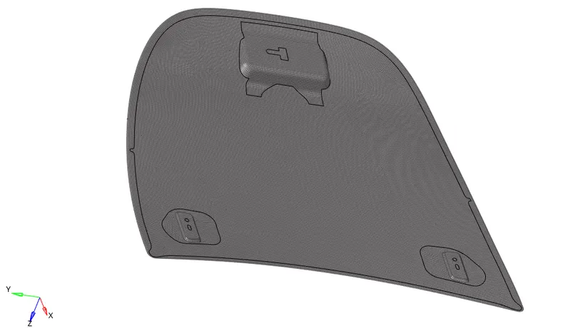
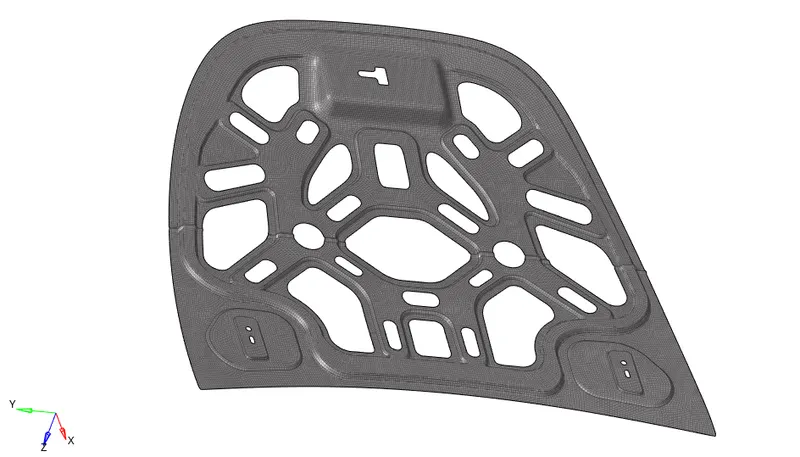
Final Model Images