Week 6-Meshing of Hood Challenge
Objective: Objective of this challenge is to create the mesh on car hood which satisfies the given quality criteria, after extracting the mid surface.
Procedure:- To start working with the challenge, first we will open the given 3D file of the hood in hypermesh window by using import geometry command.
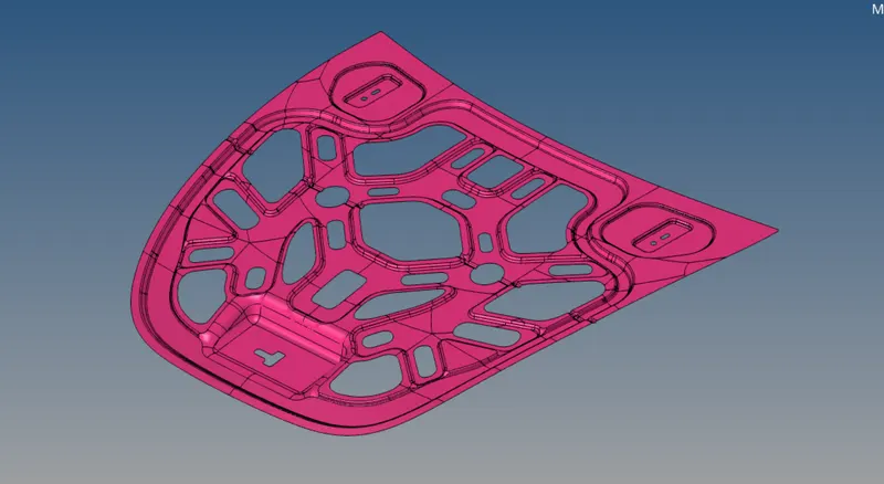
Fig 1: Showing the hood 3D file in hypermesh.
After this we will look for any geometrical errors, and try to fix if if there is any. After this we will extract the mid surface of the hood part.
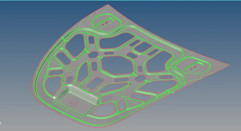
Fig 2: Showing extracted mid surface
Now, we will check the mid surface for any geometrical errors.
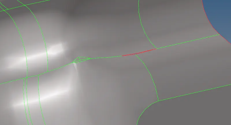
Fig 3: Showing irregularities in the auto generated mid surface.
We will fix the all geometrical errors and make the necessary cuts on geometry for better mesh flow.
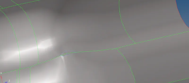
Fig 4: Showing fixed geometry.
we use the split surface using node command and other options to make a split on the surface for better mesh flow. We also suppress some edges which are not required, for better mesh flow on surfaces.
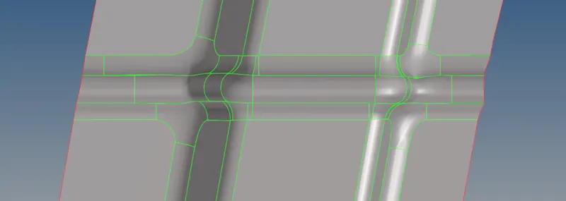
Fig 5: Showing surface before geometry cleanup
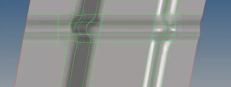
Fig 6: Showing surface after geometry cleanup
In above figures geometry cleanup is done by using various commands like- trim surface with nodes, trim surface with lines, toogle edge- which suppress or unsupress the edge. etc.
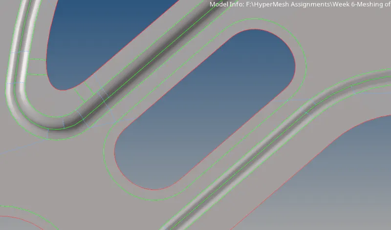
Fig 7: Showing offset edge using washer split command, for better mesh flow
After doing the geometry cleanup operation, we will proceed towards the mesh generation option.
First we will strart with inputing the required quality criterias, and target element length.
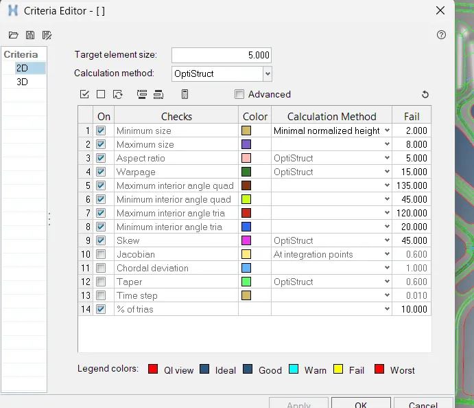
Fig 8: Showing the quality criteria input window.
After this we will start mid generation on surfaces one by one. After generating the initial mesh, we will imrove the mesh flow on the surface using various options like- smmoth, reconstrict, split quad to tria, combine two trias to quad, swap the edges of trais on nearby quads etc commands.
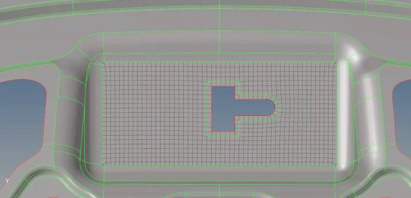
Fig 9: Showing mesh generated on a surface
By repeating the process of inital mesh generation and then improving the mesh quality by available commands on all the surfaces, mesh for the whole hood component will be generated.
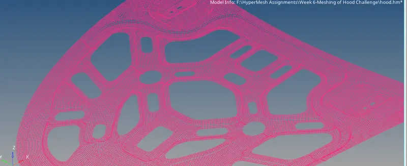
Fig 10: Showing the generated mesh for the whole hood component.
After generating the mesh, we will assign the thickness to the mid surface. T do so, first we measure the thickness of the surface using distance command. And after that we create a new PSHELL property and assign the thickness of 0.75mm to it. We can also assign the material to the PSHELL property after adding certain material property.
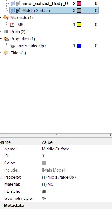
Fig 11. Showing the created PSHELL and material property assigned to mid surface.
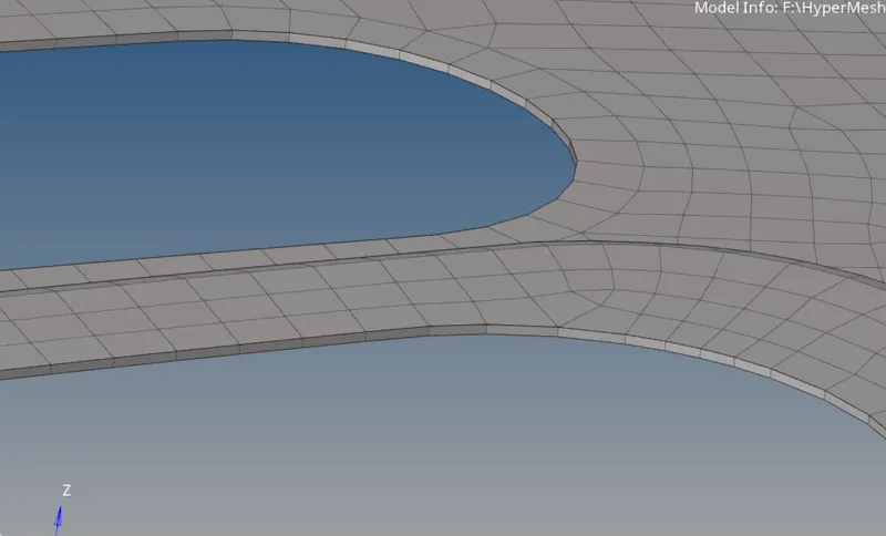
Fig 12: Shell elements after turning on show with thickness.
Conclusion:- In this challenge, we have extracted the mid surface of the hood, after clearing the geometrical errors. After that we have cleaned the mid surface and apply necessary cuts to it for better mesh generation. After that we have created the mesh on it, and improve the quality of the mesh wherever required by using various tools like- element edit, surface edit, edge edit, project nodes, project elements etc. After that we have applied the thickness to the generated mid surface. The final image of hood after mesh generation is shown below-
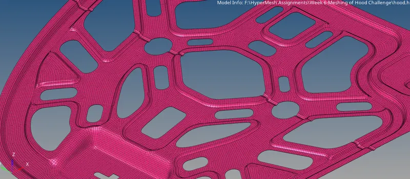
Fig 13: Showing final model image