Week 6-Meshing of Hood Challenge
AIM
- To mesh the hood component with the given quality criteria.
- To assign thickness.
GIVEN
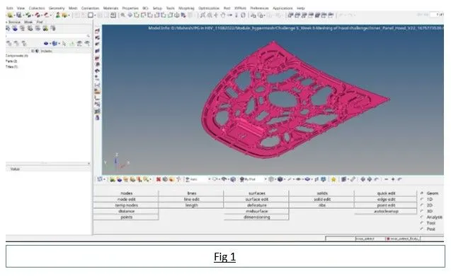
- Hood component as in Fig 1.
- Target element length = 5 Units.
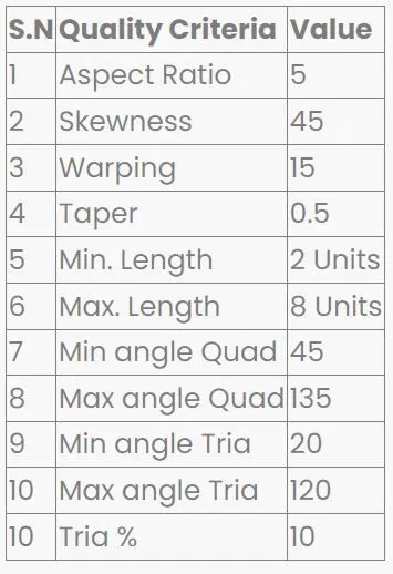
- Quality Criteria:
OBJECTIVES
- To clean up the geometrical errors in the given hood component.
- To extract the mid-surface.
- To mesh the mid-surface with the given target element size and quality criteria
- To assign thickness.
METHODOLOGY/PROCEDURE
HOUSING COMPONENT: -
1. Import the geometry:
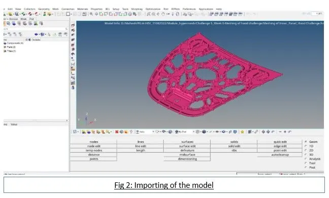
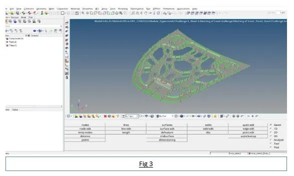
The given .hm model file is opened in Hypermesh as shown in Fig 2. Analysis of the surface of the component. Topo mode is selected in geometry color mode as shown in Fig 3.
2. Spotting of surface errors:
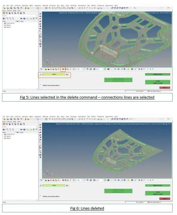
Soon after switching to topo mode, the surface errors are spotted while analyzing the surface of the component. There are connection lines as shown in Fig 4, which should be deleted to ensure proper mesh generation. The delete command can be assessed as highlighted in Fig 5 with the lines selected for deletion. Fig 6 shows the resultant hood component after deleting the connection lines. After which surface clean-up is required to ensure proper mesh generation and to have a good mesh flow. For a component at this scale and with symmetrical features, surface clean up can be carried out after taking mid-surface and applying symmetrical trim.

3. Thickness measurement:
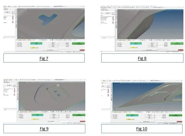
The thickness of the component must be measured in order to figure out whether the component is sheet metal or plastics. Since the hood component under analysis is sheet metal, it is having uniform thickness. In this measuring mechanism, the distances between various nodes associated with critical feature lines is also measured in order to decide which lines need to be toggled to arrive at efficient meshing and proper mesh flow. The tool used to measure thickness or distance is distance command in geom. The command can be accessed through: Geom ----> Distance ----> two points ----> points selection. The regions which are patched up are shown from Fig 7 to Fig 10.
4. Mid-surfacing:
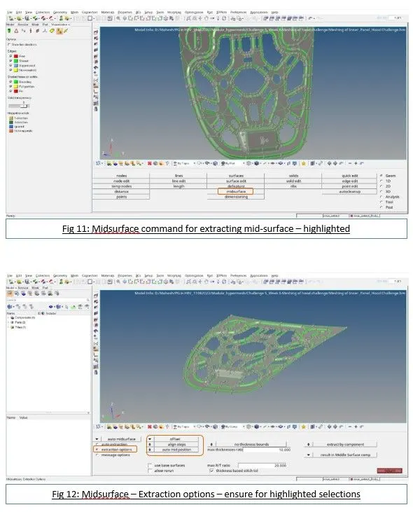
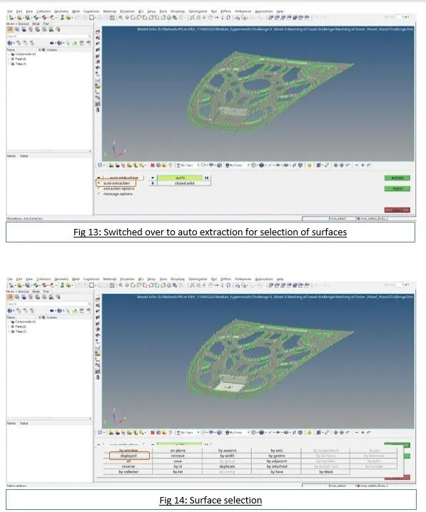
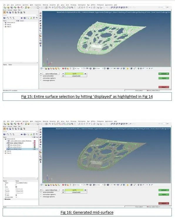
The process of extracting mid surface is mid-surfacing. Mid-surface is extracted by ‘midsurface’ command. This command can be accessed by Geom ----> Midsurface as shown in Fig 11. Under the mid-surface, extraction options is selected and other criteria are selected as shown in the Fig 12. After assigning the intended criteria, auto extraction is selected and surface- displayed is selected as shown in the Fig 15. The resultant generated mid-surface is shown in Fig 16 and hit return.
5. Symmetrical Trim:
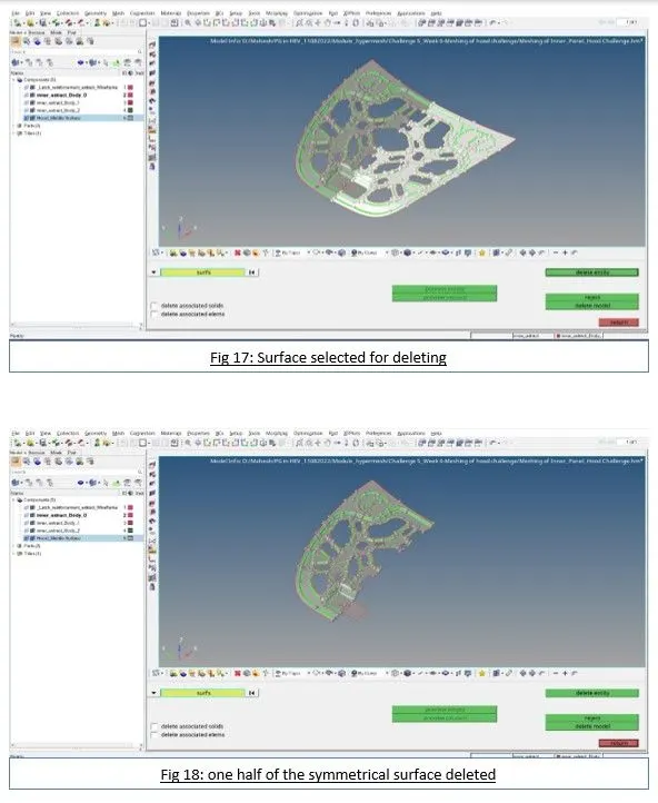
Since the hood component shape and the features in it are symmetrical in nature, it is enough to process one half of the component and make a reflect after finishing meshing. This saves time and effort in meshing the whole component of this scale. To carry out symmetrical trimming, make sure the line which runs through the center along the longitude is continues, if not connect the lines leaving the latch area. Now, the any one side of the surface will be deleted via delete command as shown in Fig 18, leaving the latch area untouched. And hit return.
6. Surface cleaning:
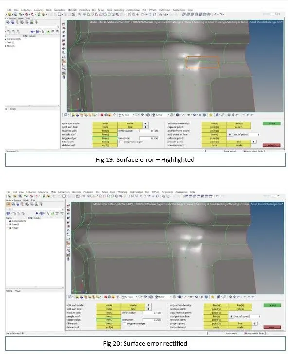
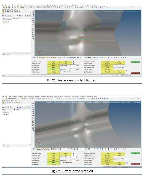
In this process, unnecessary lines or edges of features which need to be suppressed are carried out as shown in the Fig 19 to Fig 22. Similar errors in the surface need to be addressed in the same way. Additionally, the edges or lines that falls over the features like fillets or stampings need to examined and make sure that they are well over the minimum length of the element. If not, toggle the lines as per the requirement.
7. Creating washer:
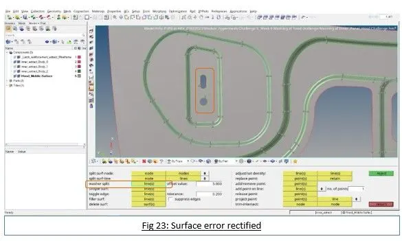
Washer should be applied in the socket or hole features as shown in Fig 23. To apply washer, washer split command is used. This command can be accessed by Geom ----> quick edit ----> washer split ----> lines (select the free edge of the line).
 +
+
8. Meshing:
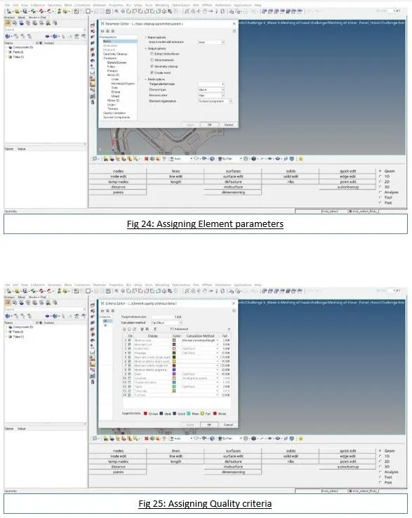
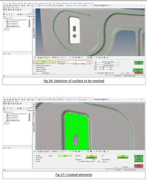
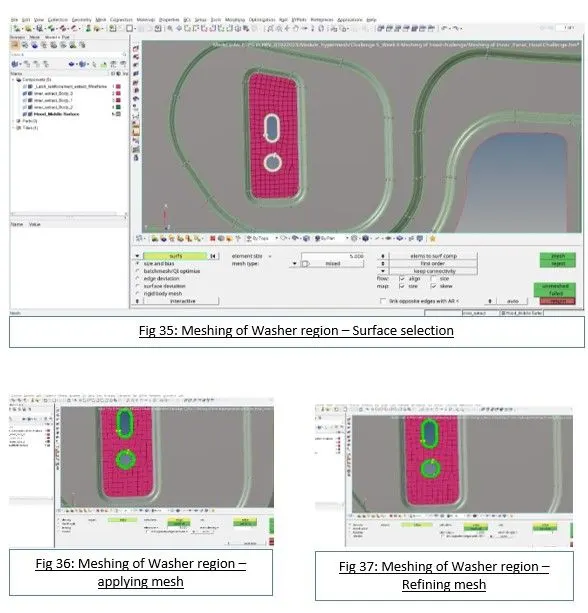
The surface which is prepared and cleanup in the above processes will be meshed in this procedure. Automesh command will be used to create mesh. Before jumping into meshing, it is mandatory and important to assign the target element size and other mesh parameters in parameter editor and the given quality criteria in the criteria editor respectively as shown in Fig 24 and 25.
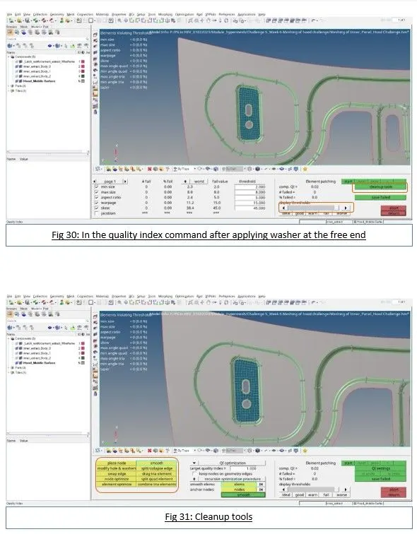
After assigning meshing parameter and quality criteria, automesh command is used to apply mesh in the hood latch seating as shown in the Fig 26. Make sure, element size is as same as target element assigned in meshing parameters. Later the washer region will be meshed as shown in the Fig 35, 36 and 37. The automesh command can be accessed by 2D ----> automesh ----> surf (select of surfaces). Hit ‘mesh’ to create mesh. If the mesh created in unsatisfactory, select elems in the drill down section and select elems and hit mesh by modifying type of elements and selecting ‘elems to current comp’. To cleanup or making the mesh as per the intended way, cleanup tools are utilized. These tools are available in quality index. This quality index can be accessed by 2D ----> quality index ----> cleanup tools as shown in Fig 30. Quality index also shows the number of failed elements, percentage of failed elements and how far the elements fail based upon the listed criteria as shown the Fig 30. Hitting cleanup tools shows the listed commands as shown in the Fig 31, which are used to get good mesh results.
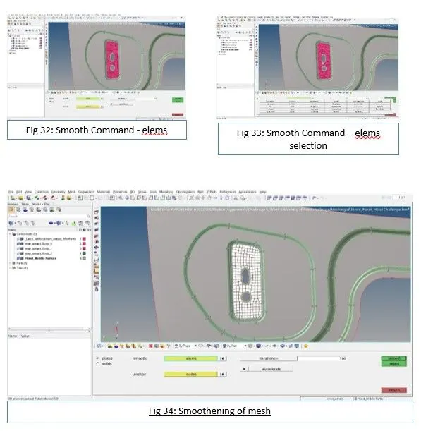
For tweaking and refining the created mesh, rebuild mesh and smooth commands are utilized. Rebuild mesh command can be accessed by 2D ----> rebuild mesh ----> elem (select of elements). Make sure, criteria and parameters are properly loaded and assigned in this command and hit rebuild. Smooth options can be accessed by 2D ----> smooth ----> plates (selection) ----> smooth: elems and hit smooth.
As shown in Fig 27, number of nodes at the free edges can be modified by left and right clicks of the mouse to get proper mesh at the free edges or at the closed edges at the mesh free end. To further modify and tune the mesh, mesh style and biasing are checked in the mesh has been tuned to get satisfactory result.
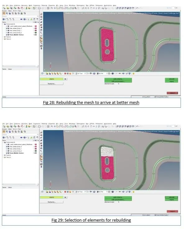
If the mesh created are not to the mark or not satisfactory, the mesh can be rebuilt with rebuild mesh as shown in Fig 28 and 29.
In Fig 28, the selected criteria indices show the worst elements in the mesh. In structural analysis, the slider which is highlighted is moved to fail to catch the failed elements, thereby to correct them. Here to access the cleanup tools, hit the cleanup tools which is highlighted which opens the page containing various cleanup tools as shown in Fig 29. Smooth option in the cleanup tools can also be utilized to smoothen the created mesh.
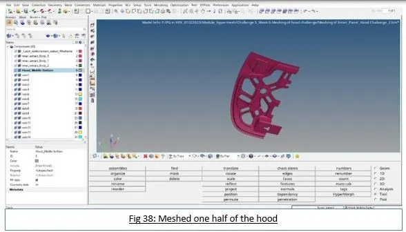
The above discussed procedure is followed in meshing rest of the surface. Care has been taken to make sure features are captured to a great extent. And care was taken to make sure the nodes along the feature lines are exactly falls on the feature line itself instead of deviating while meshing. The final meshed product or component is shown in Fig 38.
9. Equivalence:
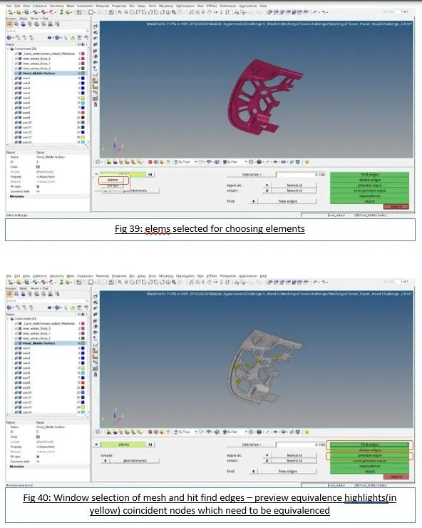
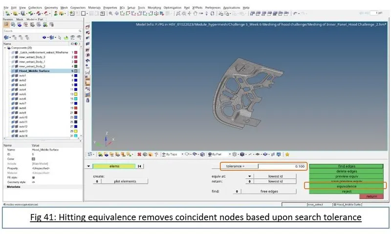
Making meshing the surface by making sure all nodes are aligned and connected properly specifically near various feature edges, there are still probability that nodes might not got pasted together at the edges, which would throw errors while solving. To find out such unpasted nodes, equivalence command is used. Equivalence is accessed in ‘edges’ command which is accessed by: Tools ----> edges ----> elems (window selection of entire mesh) ----> Find edges ----> equivalence. The entire process is shown in Fig 39 to 42. Then hit return.
10. Reflection/Symmetrical mirror of the hood:
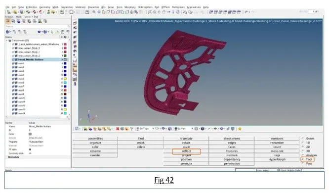
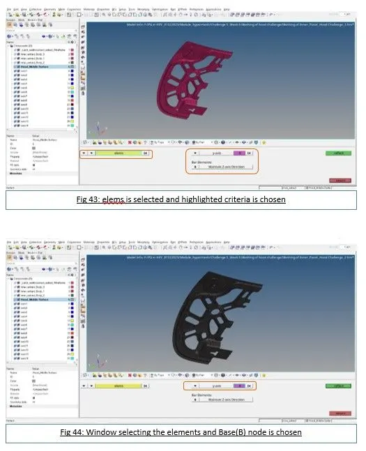
Since for simplicity purposes due to the scale of the component, the hood was symmetrically cut to half as shown in Fig 38. Now its time to retrieve another half of the meshed hood component. To carry out this process, reflect command is utilized. To access reflect command Tools ----> reflect ----> elems(window selection) is used. Other criteria like reflect about axis are chosen appropriately and hit reflect. The entire procedure of reflect is shown in Fig 42 to 47.
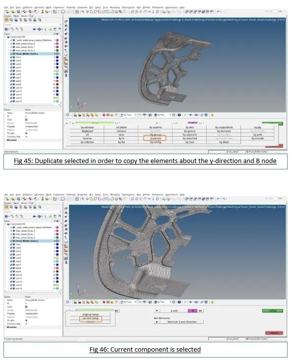
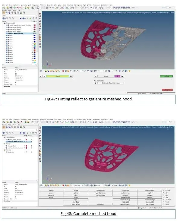
In order to make the nodes to align and to get pasted without any duplicate nodes on either side again ‘equivalence’ procedure is followed which is discussed earlier. And makes sure zero equivalence node are found in the status bar.
11. Organizing the deleting unnecessary components in the model view tree:
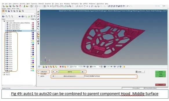
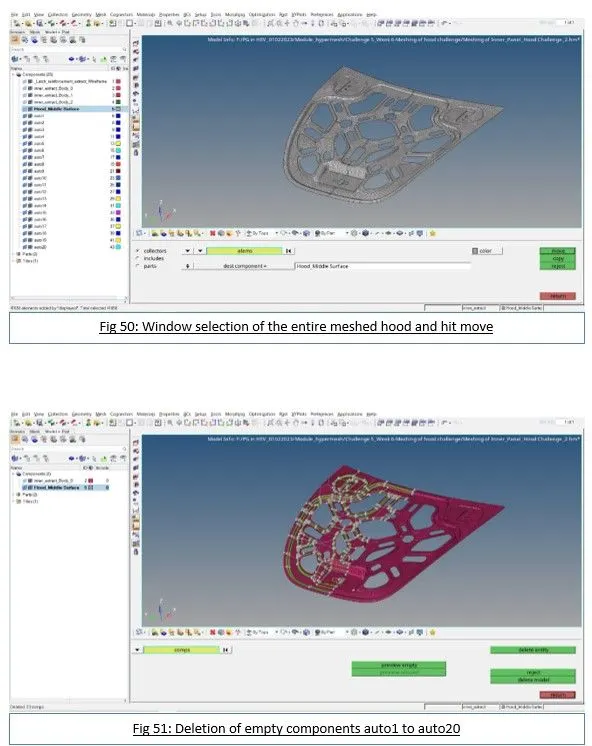
Since multiple automesh has been used to attain the intended meshing and mesh flow, there are multiple times the automesh has been formed in the model view tree as shown in Fig 49. This can be eliminated by organizing all the elements created under those automesh to the parent component, that is Hood_Middle Surface. This is carried out by accessing organize command as: Tools ----> organize ----> elems (window selection of entire hood mesh elements), and targeting all the elements to the Hood_Middle Surface component as shown in Fig 50 and hit move. Then hit return. And the empty components from auto1 to auto20 in the model view tree are deleted and the final component is shown in Fig 51.
12. Clearing off all the element errors:
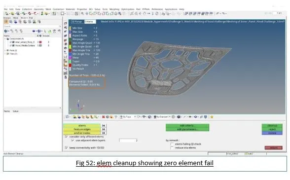
Make sure elements don’t fail under the given element criteria. Clearing off all elements of all the defects had already been discussed earlier in the same project with clean up tool under check elems to rebuild mesh to elem cleanup. and smoothening of elements for good mesh flow. The final outcome of the meshed hood with zero element defects/fails is shown in Fig 52.
13. Assigning thickness
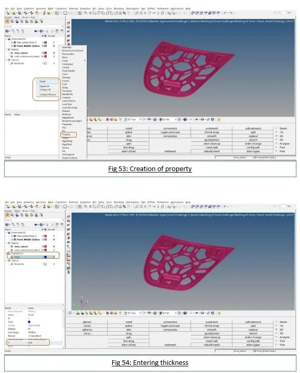
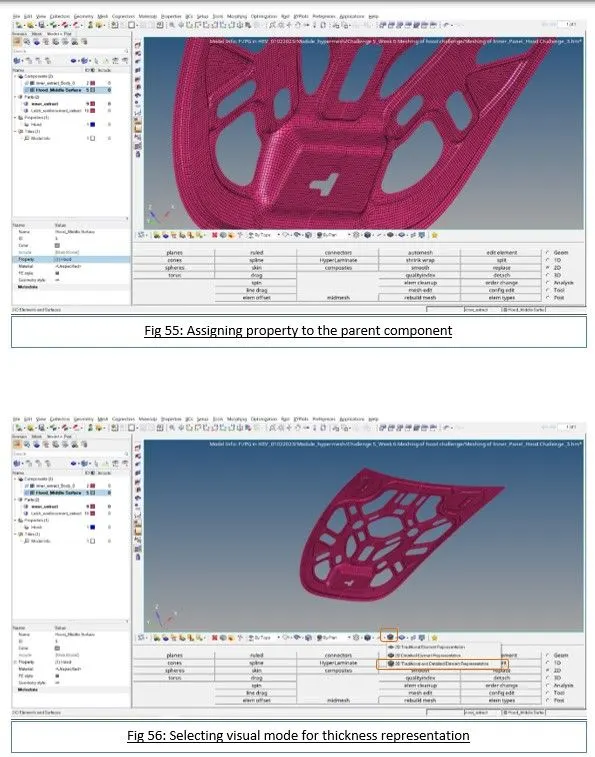
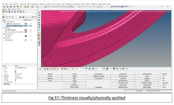
After finishing off the meshing with no element failure, it is time to assign thickness to the meshing. The thickness can be applied to property of the component. In order to create property, right-click the model view and hit create property as shown in the Fig 53. Then, the thickness can be assigned as shown as shown in Fig 54. This property is assigned to the parent component – Hood_Middle Surface as shown in Fig 55. In order to view the assigned thickness physically, go to 2D traditional elemental representation and hit 2D traditional and detailed elemental representation as shown in Fig 56. The thickness can be visually seen as shown in Fig 57.
Conclusion
Hence,
- Mid-surface of the hood has been extracted. Mid-surface correction carried out in order to get good mesh flow.
- Meshing done after dividing the surface symmetrically. Zero element defects achieved.
- Reflection/mirroring carried out to get the entire meshed hood component. Thickness assigned by assigning property.
Learning Outcome
- Hands on experience on Hypermesh or hyperwork tool.
- Attained valuable knowledge about FEA in detail with example; and with the challenge project.
- Gained valuable knowledge in extracting mid-surfaces
- Gained knowledge in surface cleanup.
- Gained knowledge in meshing and how to improve meshing.
- Tried and tested various other tools to complete the challenge the way I wanted.