Week - 4 - 2D meshing for Plastic components
AIM
Create mid-surface for all the components of the given Bottle Cap after checking the geometrical errors; and mesh the created mid-surface with the given quality criteria.
GIVEN
- Model in .ansa format.
- Quality Criteria:
S.No
Quality Criteria
Value
1
Target/Average length
1
2
Minimum Length
0.5
3
Maximum Length
3
4
Aspect
3
5
Warpage
15
6
Skewness
45
7
Jacobian
0.7
8
Minimum Quad Angle
45
9
Maximum Quad Angle
135
10
Minimum Tria Angle
30
11
Maximum Tria Angle
120
12
Tria Percentage
15
OBJECTIVES
- To create Mid-surface of various components of the given Bottle cap model
- Ensure geometric correctness for meshing
- Mesh the components with the given Quality Criteria
- Ensure to convert Shell to Solids
METHODOLOGY/PROCEDURE
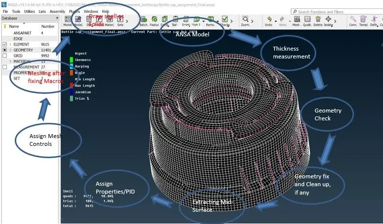
Generic procedure for working out the given Bottle Cap model is shown below:
1. Import the geometry:
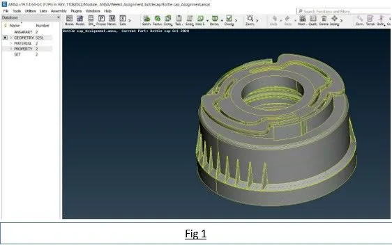
The given CAD geometry will be imported into ANSA in this process. Analysis of the given component – Bottle cap for getting start with geometry cleanup in a very effective way.
2. Geometry Checks:
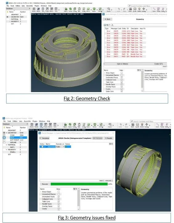
Geometry checks should be carried out to ensure whether the given surface of the components is out of geometrical errors or issues in the form of extra surfaces, triple cons, needle edges or faces, etc. If error found, it can be fixed by either auto fix option in the ANSA or by manual method. Geometry check command can be accessed in Tool bar ----> Checkup ----> Geometry. Select the parameters need to be checked as shown in red box in fig 2. The component after carrying out geometry checkup and fixes is shown in fig 3.
Thickness measurement:
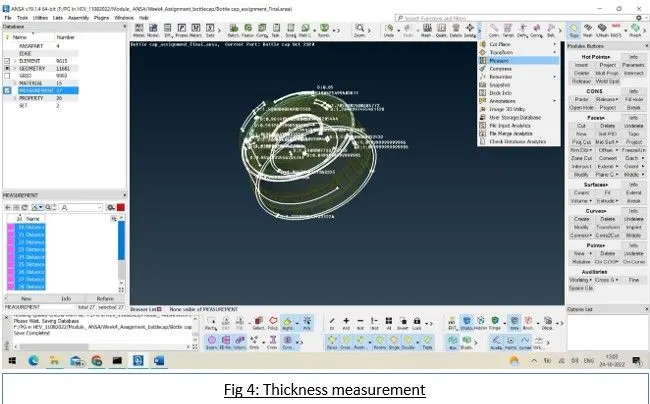
The thickness should be measured throughout the critical areas of the components as per the geometry demand and is crucial for plastic components, because plastic components have non-uniform thickness throughout the component. The command can be accessed in Utilities bar ----> measure. It is up to the engineer’s discretion to measure the thickness with the node or cons or faces options as per the component demands. The components with measured thickness are shown in Fig 4.
4. Mid-Surfacing:
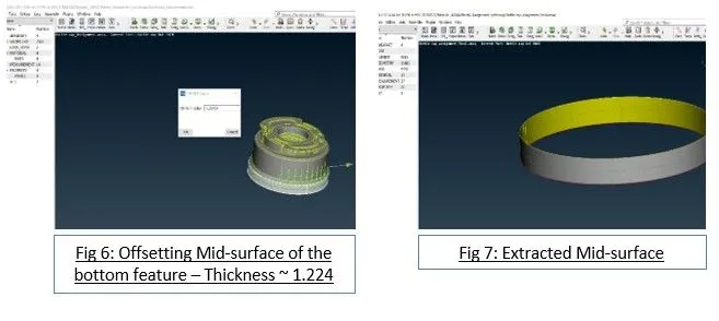
Mid-surfacing is the process of extracting mid surface of the above plastic component in order to simplify the geometry, while entering the thickness manually. Two ways to execute mid-surfacing viz., either by Offset(manual) or by Mid-Surf(auto). Former command can be accessed by Topo ----> Faces ----> Offset ---->(either a specific face can be selected or window selection can be done depending on the geometry of the component). And thickness need to be entered manually in the offset window. Property Identity(PID) need to manually set in the case of Offset command. PID can be accessed by Topo ----> Faces ----> Set PID.
While, later can be accessed by Topo ----> Faces ----> Mid Surf. In this case, thickness and property will be calculated automatically by ANSA and mid-surface will be formed.
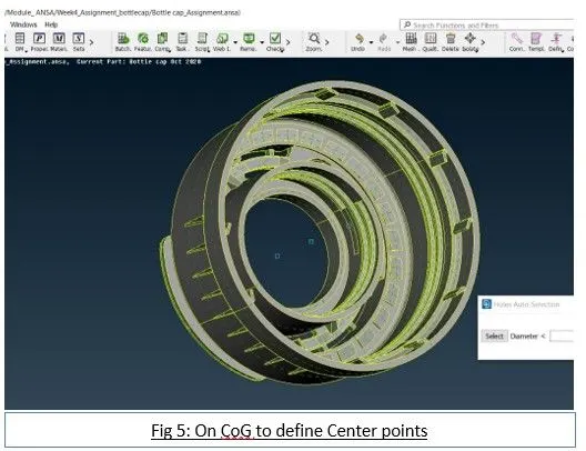
Before jumping into mid-surface extraction, center points need to be defined in order to create axis of rotation to copy-rotate the similar features that occurs at regular interval of time in the component rather than extracting the mid-surface individually, so that time can be saved. Center point can be defined by ‘on CoG’ command present under points in Topo module. So, the CoG access can be accessed by Topo ----> Points ----> On CoG
The features of the bottle cap component whose mid-surface extracted by Offset command are shown below:
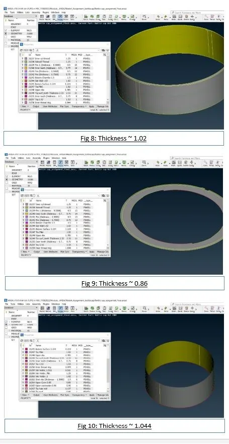
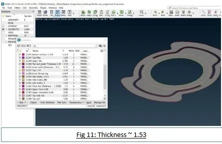
The features whose mid-surface extracted by Middle-single or Middle-multi are as follows:
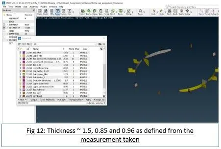
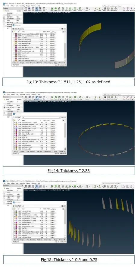
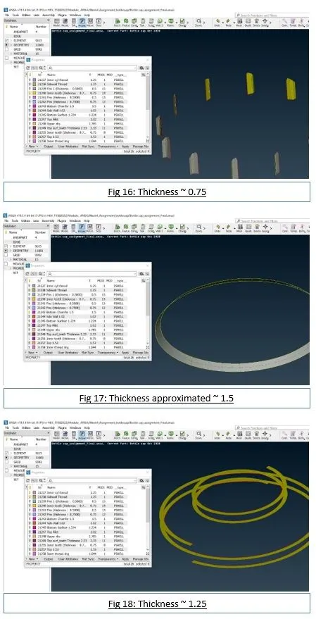
Fig 14 and 16, since the teeth like features occurs at regular intervals of time, mid-surface can be extracted once and can be copy-rotated. The rotation-copy command can be accessed by Utilities bar ----> Transform ----> Copy. The process first starts with creating ‘Middle’ curve on the surface of a single feature as shown in Fig 19. The Middle curve can be executed by Topo ----> Curves ----> Middle. Then projecting that curve on the top extracted middle surface as shown in Fig 20, which is executed by Topo ----> Cons ----> Project. Now creating a new face under faces tab as shown in Fig 21, which is executed by Topo ----> Faces ----> New-Fitted. Finally, copy-rotate the extracted mid-surface at rest of 25 instances with an angle of 13.84°, and the final outcome is shown in Fig 14.
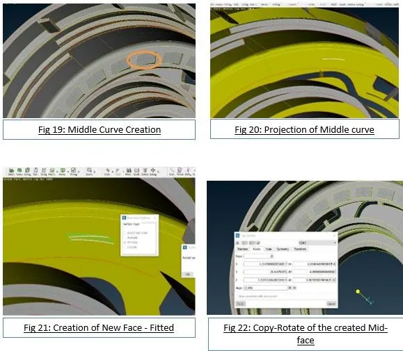
Fig 16 follows the same procedure except that, it does not involve the creation of middle curves and projection, rather simply dealt with Middle-multi. The command can be accessed as: Topo ----> Faces ----> Middle-multi. The procedure are as follows:
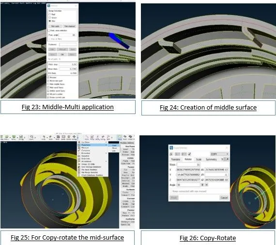
The final outcome of the procedure is shown in the Fig 16.
Fig 17, the inclined feature that connects the bottom cylindrical feature and the middle cylindrical feature is created by new faces – Fitted. Fig 18 depicts the extraction of middle surface of the threaded features in two locations. This involves new methodology since the filleted edge cannot give accurate mid. So, the filleted edge should be deformed and then middle surface can be extracted by creating middle curves by following the methods as explained in Fig 14 middle-curve creation. To deform the filleted edge ‘dach’ command need to be employed. To access the command: Topo ----> Faces ----> Dach. The middle-surface of the thread is created by projecting the created middle-curve on to the Fig 8 feature and on to Fig 10 feature to get cons at appropriate locations, and finally creating a new face/surface by utilizing the middle-curve and the projected con and the final outcome is shown in Fig 29.
And Fig 15 illustrates the extraction of Mid-surface of two sets of outer fins. Each set having two different thickness. This can be executed by the command Middle-multi, whose access and execution is already discussed in this report.
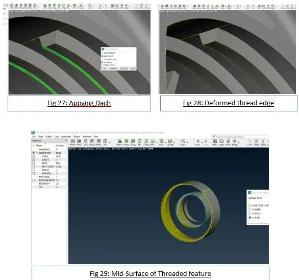
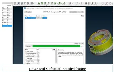
With all the surfaces are in place, geometry should be checked again for the created/extracted mid-surfaces. But now, triple and single cons need to be unchecked. Triple cons cannot be avoided since the features creates bonding between three surfaces. The result is shown in Fig 30.
Before assigning mesh controls and quality criteria, the generated mid-surfaces need to be cleaned up in order to make it compatible for meshing. To begin with the process, all unnecessary Hot Points need to be deleted as shown in fig 25 and 26 of Outer Panel of the Hood. The same process should be followed in other components when necessary. The command used to delete hot points as follows: Mesh ----> Hot Points ----> Delete (Window select the component). All unnecessary cons that hinder the flow of mesh or meshing process need to suppressed as shown in fig 23 and 24. The command used to suppress unnecessary cons as follows: Topo ----> Faces ----> Cut(right click) or Join in Mesh deck is the command to achieve suppression of cons.
Meshing
Switch to Mesh deck. Set the length of perimeter and macros to 1. The means to access and execute the length command is as follows: Mesh ----> Perimeters ----> Length.
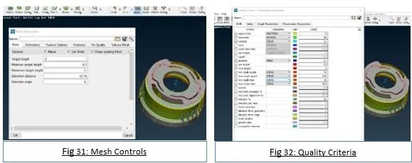
After setting perimeter length and macros, mesh controls and quality criteria need to be established as shown in Fig 31 and Fig 32. Both are present in Utilities bar side-by-side. Quality Criteria should be entered in qualities under Shells and saved. Since when needed, it can be called upon and utilized. For meshing this bottle cap component, Shell element is used, since there is no feature with thickness exceeding 5mm. In this case, first order mixed 2-D shell elements comprising of Quads and Trias are used. In the Quality Criteria module window, under presentation parameters hit ‘Elements %’ and drag ‘details on demand effect’ to All Details.
After completing all the preliminary assigning work, it is time for meshing the component. Mesh can be done by multiple tools in ANSA. For the given components, ‘Best mesh’ has been applied in order to get better result. The command can be accessed by Mesh ----> Mesh Generation ----> Best(Window Select).
The mesh generated can be improved by Reconstruction tool or Improve tool. Former can be accessed by Mesh ----> Shell Mesh ----> Reconstruct(Window Select). Whereas the latter tool has additional improvement features to offer viz., reconstruct, improve, reshape and fix quality. As per the requirement, user can utilize improve tool. To access this tool: Mesh ----> Shell Mesh ----> Improve(Window Select). Make sure that meshed components should not consists of any Offs. Whenever it is demanding use split option to split up mesh grid or to join the grid to nullify quality or to improve mesh. Split is a hybrid command which is located in: Mesh ----> Elements ----> Split. On the left-click of mouse button, it splits the element with respect to Edges or Nodes or with both as per the user choice. Upon right-click, it works as join or swapping of edges. Trias at the edge or at the perimeters should be avoided in order to reduce the stress concentration. Rotating quads and opposite trias should be avoided as well in order to get better results. Meshed bottle cap of this project is shown in Fig 33
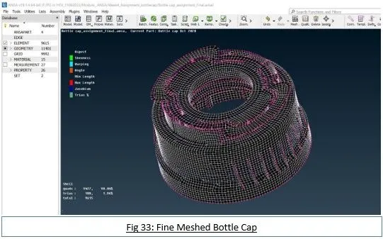
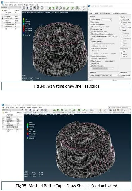
Note 1: Since the bottle cap component has features that throws up Off elements under Minimum Length criteria and Aspect Ratio. These off elements are unavailable for the given Quality Criteria. So, total number of Off elements which is unable to solve further are 36. Therefore, the criteria of the off elements are turned Off temporarily and presented in the report.[iFig 34 illustrates the process of ‘draw shell as solid’ under the presentation parameters tab of quality criteria. Fig 35 shows the complete meshed solid model of the component.
CONCLUSION
Hence,
- The Mid-surface of the Bottle Cap component is extracted after undergoing thorough geometry cleanup.
- The extracted mid-surface again cleaned up of unnecessary cons and hot points and construction lines/cons are edited conducive for proper mesh flow.
- The components are meshed individually with 1st order 2-D mixed shell elements and care taken to ensure the mesh is out of any offs or quality errors. But in this case, as stated in Note 1, few components are failing for the given Quality Criteria under minimum length and aspect ratio which are completely unavoidable for the given QC.
- Then “Draw shell as solids” activated in Quality Criteria as shown in fig 35. This option virtually converts the generated 2-D shell elements to Solid elements.
Learning Outcome
- Hands on experience on ANSA Pre-processor tool. This component alone is worked five times due to various random reasons, specifically due to the critical Off elements and finally figured out there is no means to solve it.
- Attained valuable knowledge about FEA in detail with example; and with the challenge project.
- Obtained knowledge about how to approach plastic components in FEA Pre-processing.
- Obtained knowledge about geometry cleanup; extracting mid-surface; editing the construction lines of mid-surface for meshing compatibility; and meshing plastic component in ANSA.
- Gained more momentum with the ANSA tool while working with the model, which instills much faster working with the ANSA tool in the future challenges.