Week- 5 - Solid meshing
AIM
To perform pre-processing on the given rear view mirror model.
GIVEN
- Model in .igs format.
- Quality Criteria for the Shell Mesh:
|
S.No |
Quality Criteria |
Value |
|
1 |
Target/Average length |
1 |
|
2 |
Minimum Length |
0.5 |
|
3 |
Maximum Length |
2 |
- Quality Criteria for the Solid Mesh: Solids à Collapse à Value = 0.2
OBJECTIVES
- To perform geometry cleanup on the given assembly of rear-view mirror model
- To assign mesh parameters and quality criteria parameters for 2D and 3D elements.
- To shell mesh the rear-view mirror assembly
- To perform volumetric meshing after defining the closed volume
- To perform tetrahedral meshing on the rear-view mirror assembly as per the quality criteria.
METHODOLOGY/PROCEDURE
Generic procedure for working out the given rear view mirror model is shown below:
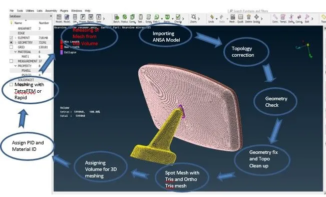 1. Import the geometry:
The given CAD geometry in the .igs format will be imported into ANSA in this process. Analysis of the given component – rear view mirror for getting start with geometry cleanup in a very effective way.
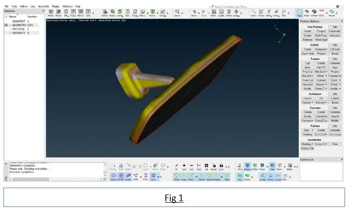 2. Topology:
Topology should be carried out in order to stich the surfaces together. To access and execute the command: Topo ----> Faces ----> Topo as shown in fig 2; and the result is as shown in the fig 3.
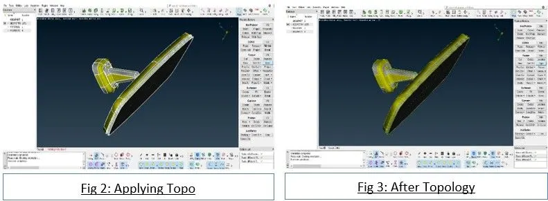
3. Geometry Checks:
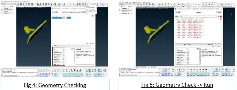
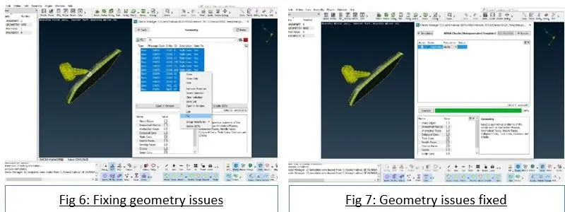
Geometry checks should be carried out to ensure whether the given surface of the components is out of geometrical errors or issues in the form of extra surfaces, triple cons, needle edges or faces, etc. If error found, it can be fixed by either auto fix option in the ANSA or by manual method. Geometry check command can be accessed in Tool bar ----> Checkup ----> Geometry. Select the parameters need to be checked as shown in red box in fig 4. The component after carrying out geometry checkup and fixes is shown in fig 5, 6 and 7.
In order to check whether the surface have proper form, switch to Mesh deck. Set the length of perimeter and macros to 1. The means to access and execute the length command is as follows: Mesh ----> Perimeters ----> Length/Macros.
4. Thickness measurement:
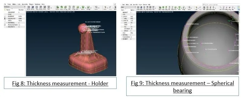
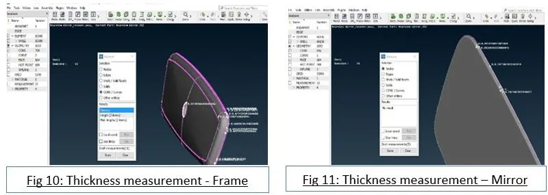
The thickness should be measured throughout the critical areas of the components as per the geometry demand (and is crucial for plastic components, because plastic components have non-uniform thickness throughout the component). The command can be accessed in Utilities bar ----> measure. It is up to the engineer’s discretion to measure the thickness with the node or cons or faces options as per the component demands. The components with measured thickness are shown in Fig 8, 9, 10 and 11.
5. Geometry Clean-up:
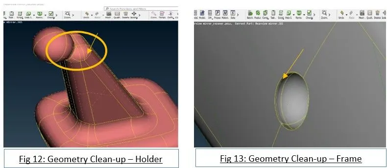
Geometry clean-up and refinement should be carried out in order to satisfy the given quality criteria. Specifically, few cons in the holder and frame components of the rear-view mirror assembly need to be deformed or neutralized. To neutralize cons which are not required, cut/join command under mesh deck can be used. To access the command: Mesh ----> Macros ----> Join. The resultant outcome is as shown in fig 12 and 13.
5. Meshing: -
5.1 2-D Shell Meshing:
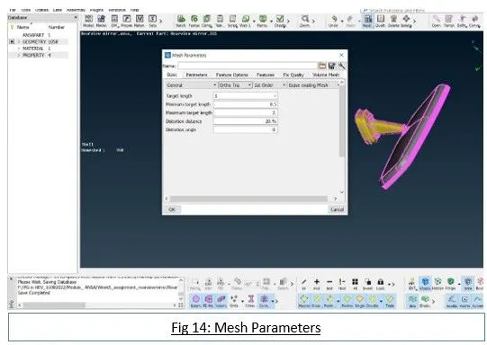
After setting perimeter length and macros, mesh controls and quality criteria need to be established as shown in Fig 14; and Fig 15 & 16. Both are present in Utilities bar side-by-side. Quality Criteria should be entered in qualities under Shells and saved. Since when needed, it can be called upon and utilized. For meshing this rear-view mirror component, Shell element is used under 2-D elements. Fillet, circular and cylindrical features should be meshed with Ortho-tria shell elements, whereas plain flat surfaces can be meshed with Tria shell elements, so that computation efforts and time can be saved. In the Quality Criteria module window, under presentation parameters drag ‘details on demand effect’ to All Details.
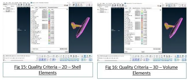
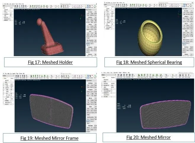
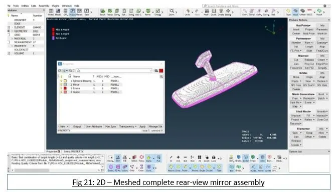
After assigning the given mesh control parameters and quality criteria, execute spot mesh under the mesh deck by switching between ortho-tria and normal tria elements appropriately to the features and surfaces where it is appropriately required. Reconstruct or improve the mesh where ever it is needed. Finally, a clean, neat and smooth tria and ortho-tria mesh should be present on the surfaces all the components of the assembly as shown in the fig 17, 18, 19 and 20. And the final rear-view assembly is shown in the fig 21.
5.2 3-D Volume Meshing
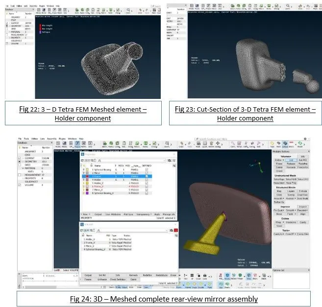
Switch to Volume Mesh Deck (V.Mesh). Before applying the volume, make sure that there should be no opening, that means the geometry is closed. For 3-D meshing, element type Tetra FEM is used for – Holder and Spherical Bearing; and Tetra Rapid is used for – Mirror and Mirror Frame. Sample of holder component of the assembly meshed with Tetra FEM is shown in the fig 22. The entire assembly of the rear-view mirror with 3-D mesh is shown in the fig 24.
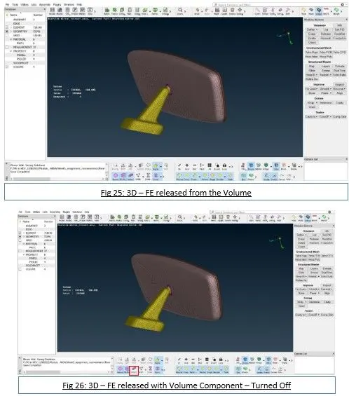
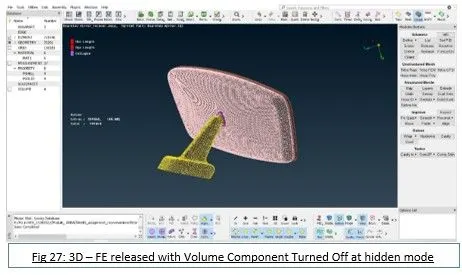
Note: Since Finite Element (FE) alone is the one used for analysis purposes, the FE is released from the generated volumetric mesh as shown in the fig 25. The command for releasing the FEs can be assessed by V.Mesh ----> Volumes ----> Release. The outcome after switching off the Volume component is shown in the fig 26 and 27.
6. CONCLUSION
Hence,
- The pre-processing on the given rear-view mirror model is successfully done after conducting topo, geometry check and surface clean up or refinement; meshing is carried out with 2-D trias and ortho trias at appropriate features.
- Volume control defined and generation of 3-D meshing with tetrahedral element is performed as shown in fig 27 with no quality issues.
Learning Outcome
- Hands on experience on ANSA Pre-processor tool involving 3-D solid elements.
- Attained valuable knowledge about FEA in detail for solid elements with example; and with the challenge project.
- Obtained knowledge about how to approach casting components which demands knowledge in solid elements in FEA Pre-processing.
- Obtained knowledge about two types of meshing algorithms viz., Tetra FEM and Tetra Rapid; and meshing plastic components in ANSA.
- Gained more momentum with the ANSA tool while working with the model, which instills much faster working with the ANSA tool in the future challenges.