Week 6 - Creating connection for Rear door
AIM
To create connections on the given rear side door finite element substrate of an automobile.
GIVEN
- Model in .ansa format.
OBJECTIVES
- To deploy appropriate connections to the given rear side door FE model substrate.
- Masses at CoGs and stiffness parameters should be assigned for appropriate connections.
METHODOLOGY/PROCEDURE
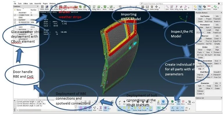
Generic procedure for working out the connections on the given rear side door model is shown below:
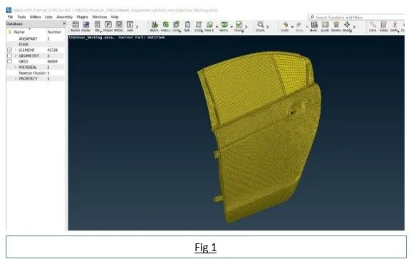
 1. Import the geometry:
The given .ansa model file will be imported into ANSA in this process. Analysis of the given FE component – for getting start with geometry cleanup in a very effective way.
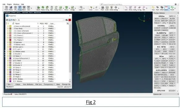
2. Assigning PID:
Since the given door assembly and its associated parts are under a single PID, it is mandatory to assign PIDs for those associated parts. PSHELL element is assigned to the property of the created PIDs and it is as shown in fig 2.
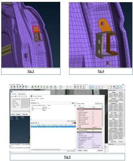
3. Creating CoG:
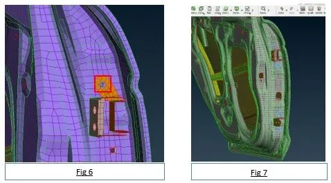
Since the hinge supposed to be fastened to the door with the help of bolt fastener, it need to have a connector element to represent in the model. For this purpose, CoG or 3D point is created, which is highlighted as shown in fig 3. Now the created CoG would eventually be converted to bolt element as shown in fig 4. Then as shown in fig 5, bolt connection is established with RBE2 body type as highlighted in fig 6 and the final bolt connection for both the hinge assembly is represented as shown in fig 7.
4. Establishing Hinge Constraint:
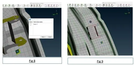
Since the door assembly is connected to the frame of any automobile, the door hinge should be established with a connection that constraints all the movements apart from rotational in Z-axis as in the case in discussion. Fig 9 represents the many node RBE2 element, used to establish rigid connection between the door flange and hinge flange, the same procedure will be followed to the other side of the hinge connection; and the selection of nodes for this purpose is shown in fig 8.
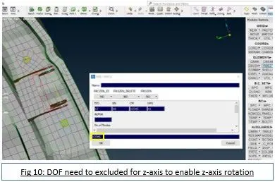
Then a 2-node RBE element is used to establish the connection between two nodes of the created RBE2 elements as shown in fig 10. Same procedure should be followed to establish this connection to the other hinge.
5. Establishing Rigid Constraints:
RBE2 element -
The door substrate supposed to have constrained elements like outer panel and inner components of door mechanism attached to the door. For this purpose, RBE2 element is used. RBE2 elements doesn’t carry any specific property ID which makes it versatile to establish connection wherever needed.
Door Handle –
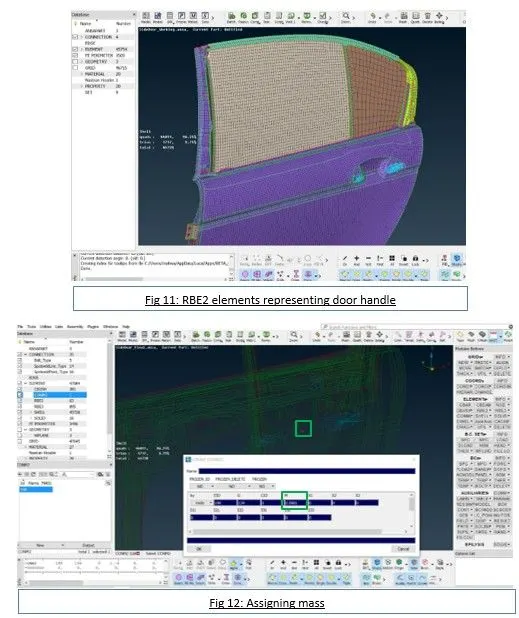
The door handle and lever mechanism are also represented in RBE2 element type. However, since the handle is not physically represented, its mass(as highlighted) should to be considered in this scenario as shown in the fig 11 and 12. The mass can be assigned by connecting the master nodes of two RBEs created in the door lever mechanism provision with a RBE2 elements. Mass can be oriented and assigned by using concentrated mass element connection CONMi. The pattern to execute this operation is: Nastran ----> ELEMENTs ----> CONMi ----> CONMI2 ----> Nodes. Mass assigned is 0.00001T, since the mass of handle is assumed as 100g approximately.
Spotweld element –
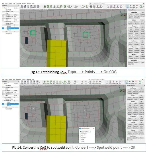
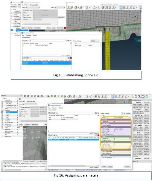
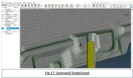
Spotwelds are other type of connection which is used to permanently fix the mechanism of any component with the door assembly. Discretion needs to be taken cared where to establish spotwelds in the door substrate. One such use of spotweld in the given substrate is in fig 13, 14, 15, 16 and 17. This same procedure is followed in establishing
Bolts –
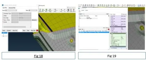
Just like spotweld which is decided by the discretion of the engineer, bolt joints in the door substrates is also upon the taken cared by the analysis engineer either by discretion or with knowledge. One bolt connection established in the door substrate is shown in fig 18 and 19. The procedure of establishing bolt element is same as discussed in door hinge connection earlier.
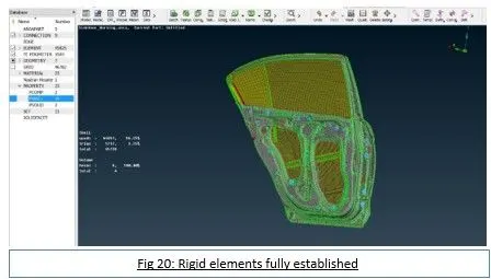
And the door substrate after establishing all the rigid connections is shown in fig 20.
6. Establishing weather strips:
Weather strips are used for weather proofing and dust proofing in an automobile around the moving glass and permanent glass in the door; and between the door and car body as well. The weather strips in the ansa is established by using RBE3-CBUSH elements. The following procedure provides the steps in establishing CBUSH elements to both the moving and fixed windows alone.
In this process of establishing CBUSH elements as weather strips, separate ‘bush’ element will be created automatically or manually with specific properties, importantly stiffnesses; and assign that to bush elements. The process of creating or establishing CBUSH elements is as follows:
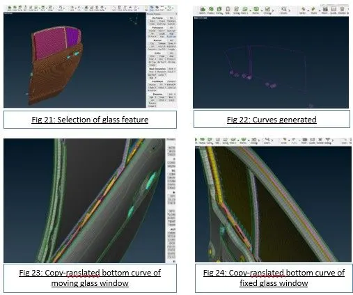
- Creating feature curve – first and foremost, curve should be extracted from the edges of the glass. For this Feat2curve command is used. To access the command: Mesh ----> Perimeters ----> Feat2curve ----> Selection of feature(as shown in fig 21). Curves will be generated as shown in fig 22. The bottom curve alone should be translated to half the distance of farthest side with the door frame using the command copy-translate in order to establish proper and uniform CBUSH connections between the glass and door frame as shown in fig 23 and 24.
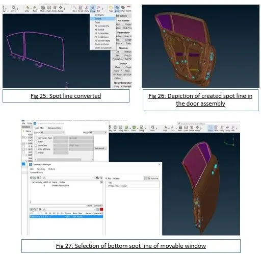
- Conversion of curves to spot line – the created curves are converted to spot line in convert under assembly as shown in fig 25. Care should be taken to ensure each curve is selected at a time, not at once. The translated curves should be selected as well for conversion to spot line. The means to access the command: Assembly ----> Convert ----> Curves.
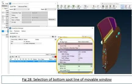
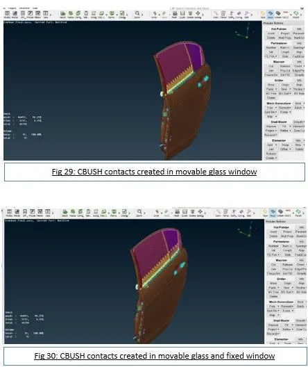
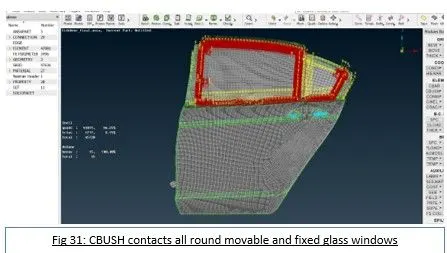
- Establishing CBUSH contacts – the CBUSH contacts are created or established using connection manager. Firstly, the bottom spot line of the moving glass and fixed glass are selected and contacts established as shown in fig 27, 28 and in 29, 30. Subsequently other spot lines are elected and converted to CBUSH contacts. FE element type should be chosen as: RBE3-CBUSH-RBE3; and PBUSHid should be assigned under the body as shown in the fig 27.
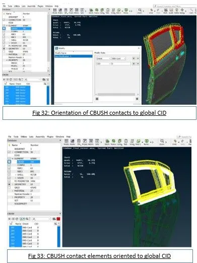
The final outcome of establishing CBUSH element to represent weather strips is shown in fig 31. The analysis shows that the orientation of CBUSH elements is different to one another with respect to their vector. In order to make them orient in one direction, that is the direction of global axis. To execute this, all CBUSH elements are selected as shown in fig 32, modify the orientation from vector to coordinate system as shown in fig 33, then add Coordinateid(CID) with the value = 0, as shown.
Finally, the door to body weather strip representing with spot line alone is also created by following the same steps as that of glass windows, which is as depicted in fig 34.

7. CONCLUSION
Hence, creation of appropriate connections on the given rear side door finite element substrate of an automobile by considering CoG of door handle mass is successfully done.
Learning Outcome
- Hands on experience on ANSA Pre-processor tool involving connections.
- Attained valuable knowledge about connectors in FEA in detail with example; and with the challenge project.
- Obtained knowledge about connector elements like RBE2, RBE3-HEXA-RBE3, RBE3-CBUSH-RBE3 and CONMi elements in ANSA.
- Familiarized with ANSA tool while working with the model, which instills much faster working with the ANSA tool in the future challenges.