Week 3 - 2D meshing for sheet metal
AIM
Create mid-surface for all the components of the given Hood assembly model after checking the geometrical errors; and mesh the extracted mid-surface with the given quality criteria.
GIVEN
- CAD Model in .stp format.
- Quality Criteria:
|
S.No |
Quality Criteria |
Value |
|
1 |
Target/Average length |
5 |
|
2 |
Minimum Length |
2 |
|
3 |
Maximum Length |
7 |
|
4 |
Aspect |
3 |
|
5 |
Warpage |
15 |
|
6 |
Skewness |
45 |
|
7 |
Jacobian |
0.7 |
|
8 |
Minimum Quad Angle |
45 |
|
9 |
Maximum Quad Angle |
135 |
|
10 |
Minimum Tria Angle |
30 |
|
11 |
Maximum Tria Angle |
120 |
|
10 |
Tria Percentage |
15 |
OBJECTIVES
- To create Mid-surface of various components of the given Hood model
- Ensure geometric correctness for meshing
- Mesh the components with the given Quality Criteria
- Ensure to convert Shell to Solids
METHODOLOGY/PROCEDURE
Generic procedure for working out the given Hood model is shown below:
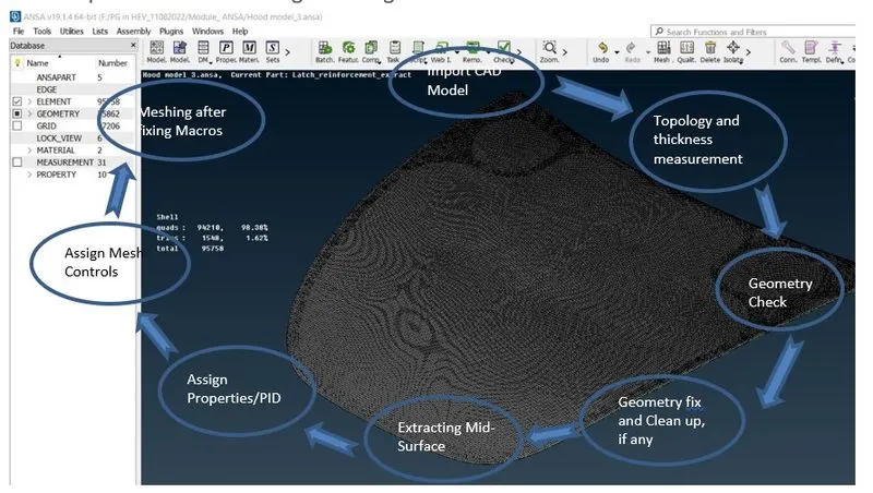
1. Import the geometry:
The given CAD geometry will be imported into ANSA in this process. After analyzing the component and its assembly, ‘Lock views’ are created and saved for all the six components viz., Outer Hood panel, Inner Skeleton/Panel, Latch reinforcement, Right and Left Hinge.
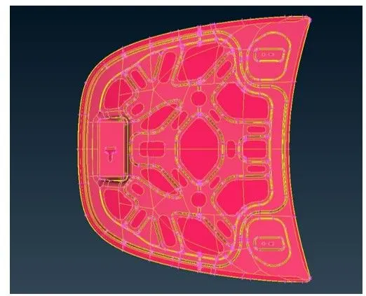
2. Topology:
Outer Hood panel is first considered for working out and meshing. This can be selected by either picking show only in the created Lock View menu or in Properties/PID list. Topo command can be accessed in Topo deck ----> Faces ----> Topo. In fact, this topology step is common to all the components of the given Hood assembly as shown below:
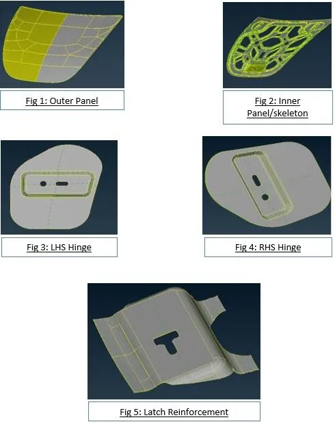
3. Geometry Checks:
Geometry checks should be carried out to ensure whether the given surface of the components is out of geometrical errors or issues in the form of extra surfaces, triple cons, needle edges or faces, etc. If error found, it can be fixed by either auto fix option in the ANSA or by manual method. Geometry check command can be accessed in Tool bar ----> Checkup ----> Geometry. The components after carrying out geometry checkup are shown below:
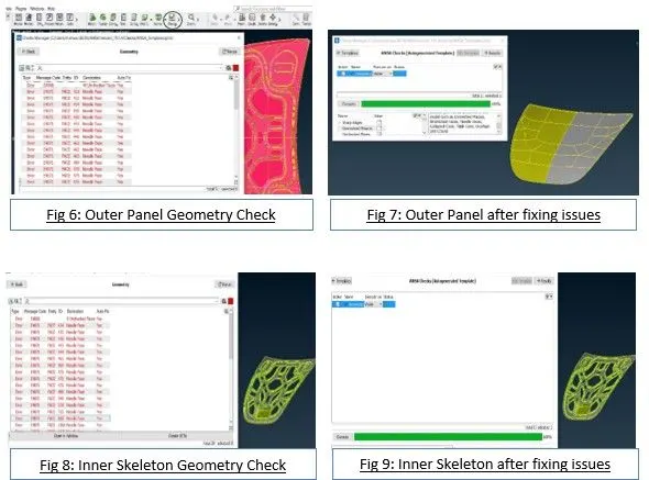
The same procedure applies to LHS and RHS hinge and Latch reinforcement.
4. Thickness measurement:
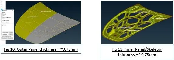
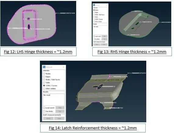
The thickness should be measured throughout the critical areas of the components as per the geometry demand. However, sheet metal components have uniform thickness while plastic components have non-uniform thickness throughout the component. The command can be accessed in Utilities bar ----> measure. It is up to the engineer’s discretion to measure the thickness with the node or cons or faces options as per the component demands. The components with measured thickness are shown below:
5. Mid-Surfacing:
Mid-surfacing is the process of extracting mid surface of the above sheet metal components in order to simplify the geometry, while entering the thickness manually. Two ways to execute mid-surfacing viz., either by Offset(manual) or by Mid-Surf(auto). Former command can be accessed by Topo ----> Faces ----> Offset ---->(either a specific face can be selected or window selection can be done depending on the geometry of the component). And thickness need to be entered manually in the offset window. Property Identity(PID) need to manually set in the case of Offset. PID can be accessed BY Topo ----> Faces ----> Set PID.
While, later can be accessed by Topo ----> Faces ----> Mid Surf. In this case, thickness and property will be calculated automatically by ANSA and mid-surface will be formed. Either Boolean operations need to be carried out to access the formed mid-surface or just by toggling the properties in the property manager, one can access the mid surface. Care should be taken to ensure whether the material defined or not in the material identity(MID) manager located in the “Lists” adjacent to PID.
The mid-surfacing of the components of the given Hood assembly are shown below:
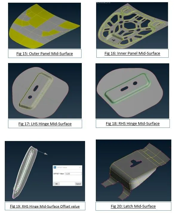
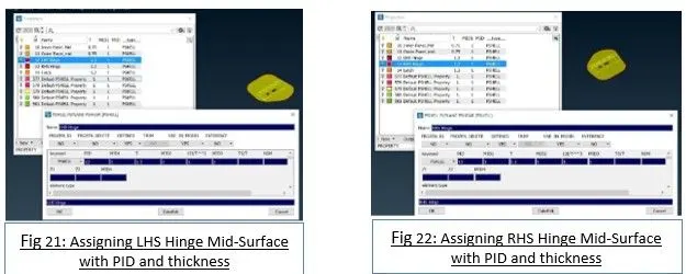
Apart from Hinges, Mid-surface as in fig 17, 18 and 19, all the other components Mid-surface are extracted with Mid-Surf command, while mid-surface of Hinges has been extracted with Offset command and its offset value is shown in fig 19. Thickness and PID have been assigned to the same and is shown as in fig 21 and fig 22.
PID manager checked and data edited and assigned for the created mid-surfaces as per convenience.
Before assigning mesh controls and quality criteria, the generated mid-surfaces need to be cleaned up in order to make it compatible for meshing. To begin with the process, all unnecessary Hot Points need to be deleted as shown in fig 25 and 26 of Outer Panel of the Hood. The same process should be followed in other components when necessary. The command used to delete hot points as follows: Mesh ----> Hot Points ----> Delete (Window select the component). All unnecessary cons that hinder the flow of mesh or meshing process need to suppressed as shown in fig 23 and 24. The command used to suppress unnecessary cons as follows: Topo ----> Faces ----> Cut(right click) or Join in Mesh deck is the command to achieve suppression of cons. The same procedure should be followed for suppression of cons wherever is necessary in other components as well.
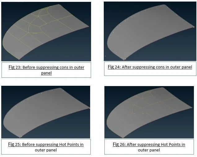
Note: Depiction of suppressing of hot points and cons in the report limited to the outer panel alone due to the reason that, it is the same procedure in the other components as well; and to reduce the pages and size of the report content as well.
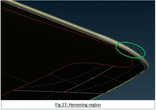
In this process, hemming region of the Outer Panel is deformed in order to avoid mesh failure due to Min. length criteria. One of central con has been suppressed to avoid mesh failure and the edge has been deformed as shown in fig 27.
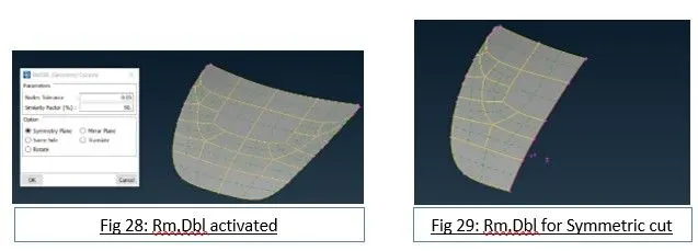
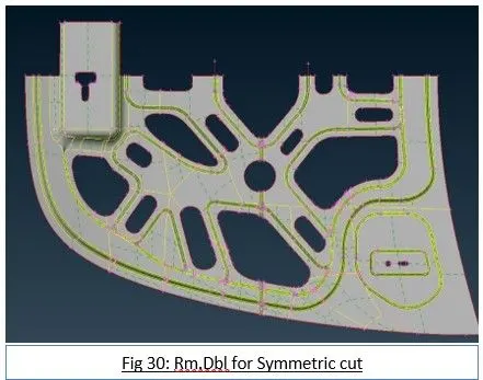
After cleaning up geometry, execute topo once and do a geometry check again. Apparently, it seems Outer Panel and Inner Panel/skeleton of the Hood assembly are symmetry. To reduce time and complexity, these components are symmetrically divided by the command Rm.Dbl. This command can be accessed by Topo ----> Faces ----> Rm.Dbl. ANSA does the job of dividing the components symmetrically. Delete one of the divided surfaces as shown in the fig 28 and 29. Fig 30 shows the symmetrical cut of Inner skeleton of the Hood.
6. Meshing
Switch to Mesh deck. Set the length of perimeter and macros to 5 as shown in Fig 32 and 33. This length is same for all the components in the Hood assembly. The means to access and execute the length command is as follows: Mesh ----> Perimeters ----> Length
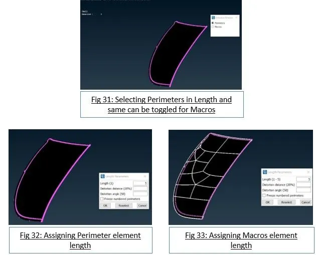
Note: Depiction of assigning length for perimeters and macros in the report limited to the outer panel alone due to the reason that, it is the same procedure in the other components as well; and to reduce the pages and size of the report content as well.
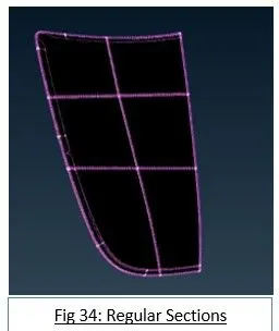
In order to achieve good mesh flow, create known or uniform and regular sections on the outer panel surfaces alone due to vast surface area as shown in Fig 34. This is also called as generated constructed lines. To achieve this following command should be executed: Mesh ----> Macros ----> Cut(pick starting and ending node)
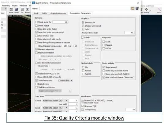
After execution of Symmetric cut in Outer Panel and Inner Skeleton and sectioning the surface of Outer Panel, mesh controls and quality criteria need to be established. Both are present in Utilities bar side-by-side. Quality Criteria should be entered in qualities under Shells and saved. Since When needed, it can be called upon and utilized. For meshing sheet metal components, Shell elements are widely used. In this case, first order mixed 2-D shell elements comprising of Quads and Trias are used. In the Quality Criteria module window, under presentation parameters hit ‘Elements %’ and drag ‘details on demand effect’ to All Details and as shown in the below fig 35.
After completing all the preliminary assigning work, it is time for meshing the component. Mesh can be done by multiple tools in ANSA. For the given components, ‘Best mesh’ has been applied in order to get better result. The command can be accessed by Mesh ----> Mesh Generation ----> Best(Window Select).
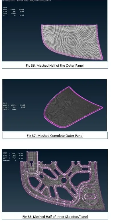
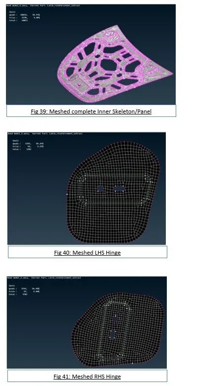
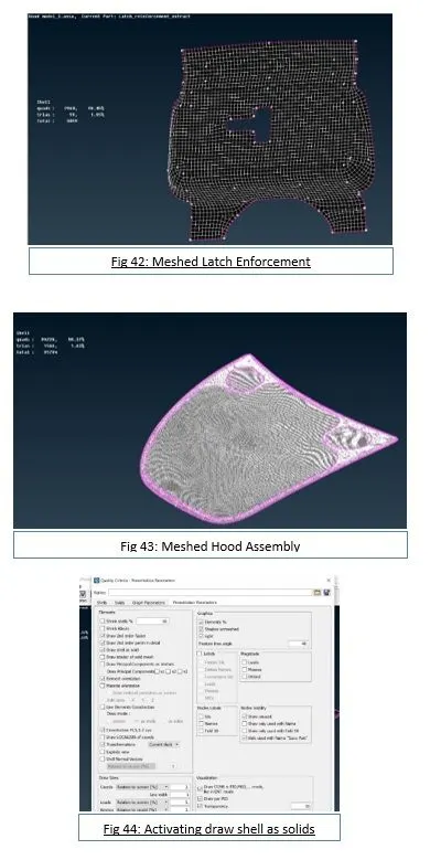
The mesh generated can be improved by Reconstruction tool or Improve tool. Former can be accessed by Mesh ----> Shell Mesh ----> Reconstruct(Window Select). Whereas the latter tool has additional improvement features to offer viz., reconstruct, improve, reshape and fix quality. As per the requirement, user can utilize improve tool. To access this tool: Mesh ----> Shell Mesh ----> Improve(Window Select). Make sure that meshed components should not consists of any Offs. Whenever it is demanding use split option to split up mesh grid or to join the grid to nullify quality or to improve mesh. Split is a hybrid command which is located in: Mesh ----> Elements ----> Split. On the left-click of mouse button, it splits the element with respect to Edges or Nodes or with both as per the user choice. Upon right-click, it works as join or swapping of edges. Trias at the edge or at the perimeters should be avoided in order to reduce the stress concentration. Rotating quads and opposite trias should be avoided as well in order to get better results. Meshed components of this project are shown in figs 36 to 42.
In order to generate the other half of the symmetrically cut outer panel and the inner skeleton, transform option need to be used with symmetry. The option can be accessed in Utilities bar as: Transform ----> Copy ----> Entities(window select the component) ----> Transform(after hitting the Scroll) ----> Default Symmetry Plane ----> Apply ----> OK(under Transformation options with all defaults) ----> Finish. Complete meshed geometry of the outer panel and inner skeleton will be generated as shown in fig 37 and fig 39.
Note: All generated construction cons/lines need to be removed without fail
CONCLUSION
Hence,
- The Mid-surface of the car hood assembly components are extracted after undergoing thorough geometry cleanup.
- The extracted mid-surface again cleaned up of unnecessary cons and hot points and construction lines/cons are edited conducive for proper mesh flow.
- The components are meshed individually with 1st order 2-D mixed shell elements and care taken to ensure the mesh is out of any offs or quality errors.
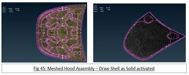
- The components are assembled after meshing to form car hood; and the “Draw shell as solids” activated in Quality Criteria as shown in fig 44. This option virtually converts the generated 2-D shell elements to Solid elements which is depicted in fig 45.
Learning Outcome
- Got the First-hand experience of ANSA Pre-processor tool.
- Attained valuable knowledge about FEA in detail with example; and with challenge project.
- Obtained knowledge about how to approach sheet metal components in FEA Pre-processing.
- Obtained knowledge about geometry cleanup; extracting mid-surface; editing the construction lines of mid-surface for meshing compatibility; and meshing in ANSA.