Week 6-Meshing of Hood Challenge
AIM:
The aim of this procedure is to mesh a given component while meeting specified quality criteria and to assign properties and thickness to the component.
OBJECTIVE:
The objective is to mesh the model components separately by creating a separate mid-surface and using the 'Mixed' option to generate the mesh, as the model is being prepared for crash and safety simulations. We will also understand the quality index and model check options available in HyperMesh.
PROCEDURE:
Step 1: Import and Cleanup Geometry:
To begin, import the geometry by selecting "File" → "Import" → "Import geometry" → "Import" and choosing the appropriate file. In this case, the file name is "hood.stp".
After importing the geometry, check for any missing surfaces or triple cons. If there are no errors present in the geometry, the geometry is ready for the mid-surface extraction.
Step 2: Mid-Surface Generation:
Next, remove the solid before midsurfacing by selecting "Delete" → "Solid" → "Select solid" → "Delete entity". Then, using "By Topo" geometry color mode, check the model for free lines and errors.
Once checked, produce a mid-surface for each component separately and name them appropriately.
Step 3: Auto Cleanup:
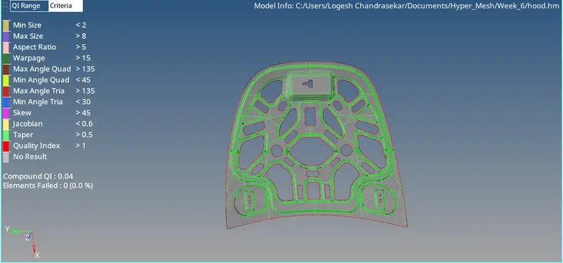
After mid-surface generation, check for any free lines and errors. Then, save the criteria file by selecting "Preferences" → "Criteria file settings". Use the auto-cleanup option to toggle unwanted lines and small pinholes for better meshing.
Step 4 : Meshing
: Meshing using Auto Mesh Tool:
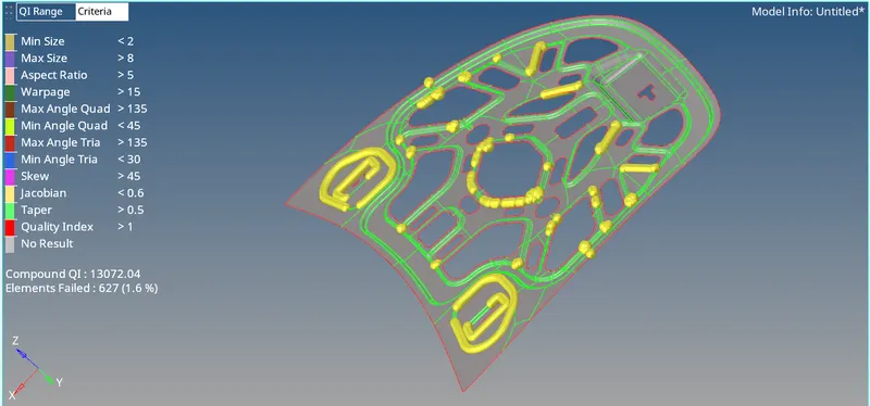
To mesh the component, we will use the Auto Mesh Tool in the 2D tab. This tool can also be accessed by pressing the F12 key. We will select the area that needs to be meshed and adjust the element size to 5. We will choose the mesh type as "mixed" and select the surface to be meshed.
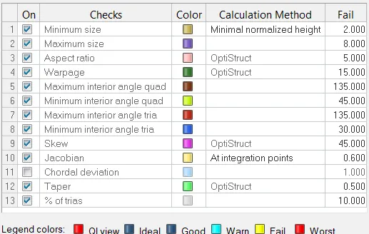
After meshing is done, we will check the quality of the mesh using the Quality Index option available in HyperMesh. We will also check the model using the Model Check option to ensure that the mesh is appropriate for the analysis.
The 'element optimize', 'drag tria element', 'place nodes', 'split quad elements', and 'combine tria elements' are frequently used tools for cleanup operations in the mesh.
The 'drag tria element' tool is used to reposition tria elements in the mesh. Two opposite trias can be moved together to form a quad element, improving the mesh quality.
The 'place nodes' tool is used to adjust the position of nodes in an element, allowing for small modifications to its shape or alignment.
The 'split quad element' tool can be used to divide a quad element into two trias, providing flexibility in the mesh structure for better overall quality.
The 'combine tria elements' tool can be used to merge adjacent tria elements into a quad element, although this can also be achieved with the 'drag tria element' tool.