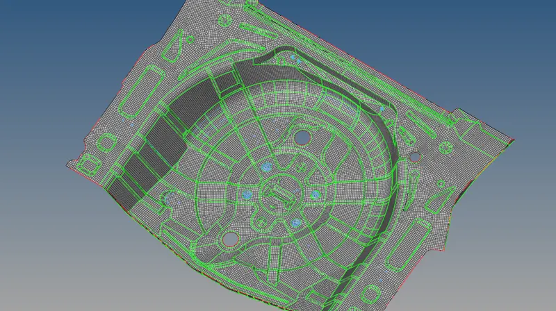
Project 1-Meshing of Rear Wheel Holder challenge
Objective: Meshing of rear wheel holder using hypermesh and assigning suitable thickness to them.
PROCEDURE:
- Import the CAD model in IGES format to HyperMesh using Files > Import > Geometry > IGES Format > Select File > Import.
- Check the component for any missing surfaces or deformations.
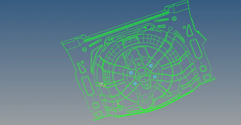
- To ease mid-surfacing and meshing, divide the component into 5 subparts.
- Since the component is symmetric about the y-axis, delete half of the component to save time.
- Perform topology on each subpart and check for any errors.
- Use the Offset + Planes + Sweep option under Geom > Midsurface > Extraction Options > Auto Extraction > Surfs > Displayed > Extract to extract mid-surfaces for each subpart.
- Perform geometrical clearance on each mid-surface using the toggle and mask options. Do not use the auto clean option.
- Mesh each subpart's mid-surface with mixed elements with a target length of 5mm, minimum length of 2mm, and maximum length of 8mm. Use the 2D > Automesh option to mesh each subpart.
- Correct any error elements using cleanup tool options like Place Node, Rebuilt Mesh, and Combine Tria Element.
- Use the Reflect option to form the complete geometry and mesh over it.
- Clean the geometry by closing holes below 3mm, toggling unwanted lines, defeaturing small diameter fillet areas, splitting surfaces into parts, filling empty surfaces, adding or removing points in lines, and deleting unwanted surfaces.
- Use the Quick Edit tool under Geometry to edit the mesh, with the shortcut key F11.
- To avoid errors caused by unconnected trim lines in curved surfaces, use the Split Surf-Node/Split Surf-Line option.
- To avoid errors caused by free edges, use the Toggle Edge option.
- Use the Filler Surf option to fill missing surfaces.
- To eliminate yellow-colored non-manifold edges, use the Geom > Quick Edit option.
- Use the Shell Meshing option after skin extraction.
- Use the Solid Meshing option for casting and molding products.
- Adjust the mesh density using the Density option in Automesh.
- Split surfaces into small parts for even mesh flow.
- Use the Smoothing option under 2D to align elements properly.
- Use the Rebuild Mesh option under 2D to modify the mesh with respect to the surface in complex regions.
- Use the Quality Index tool under 2D to check the quality of the elements.
- Use the Clean Up Tools option under Quality Index to eliminate all off elements, including smoothing, drag Tria elements, element optimize, combine Tria element, split Quad element, and place node.
- Use 2D > Element Clean-Up option to automatically remove quality issues.
- Remove free edges within the geometry by selecting the elements and previewing equiv and then using the equivalence option under Tool > Edge > Select Element by Displayed > Find.
- If free edges are still present, use the Replace Node option under 2D > Replace/F3 to manually change the position of a single node.
- Assign the thickness by creating a property. Right-click on the tab bar and select the Create option.
- Use the Assign option to assign the thickness to the model.
- Verify that the mid-surface and meshing have been done according to the given quality criteria for the backdoor component.
CONCLUSION
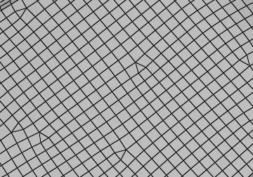
In conclusion, the geometrical errors in the CAD model have been successfully resolved and meshing has been performed with the given element quality criteria. The entire process, from importing the CAD model, geometry clean up to mesh improvement, has been executed successfully. The next step of applying load and boundary conditions will be performed in the upcoming phases.