Week 6-Meshing of Hood Challenge
NOTE:
I belongs to fast track 21 program on Hypermesh course. As requested by instructor, i have done extracting midsurface and meshing on inner_extract and Latch_reinforcement_extract alone.
AIM:
To extract the mid surface for the given components and perform 2d meshing on the midsurface based on the given quality criteria with proper mesh flow.
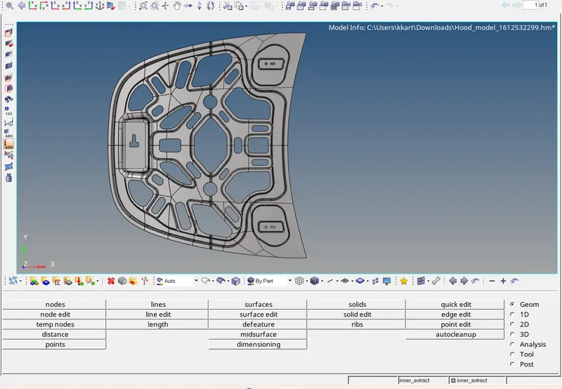
GIVEN CAD MODEL:
PROCEDURE:
- For importing the given step file into hypermesh workplace go to import>geometry>select the geometry type as step>browse for the model> click import.
- Now in the geometry colour mode>select By topo> click on visible fixed points to see all the hardpoints present in the surfaces and edges of the component.
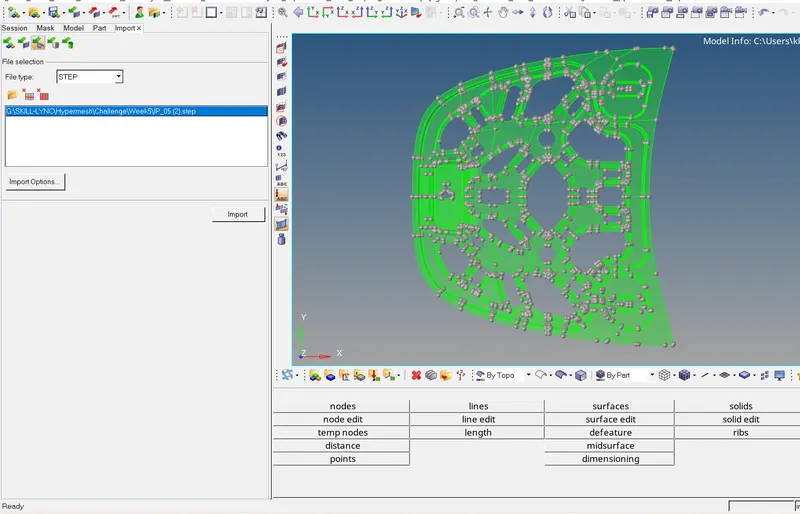
- As you see the model appeares transperent green as because it is a solid. So now we gonna keep one component that we gonna work on and hide all the other components.
- Now to delete the solids go to delect>solid>displayed>delete entity
- Now there will only surfaces are available and solid is now deleted.
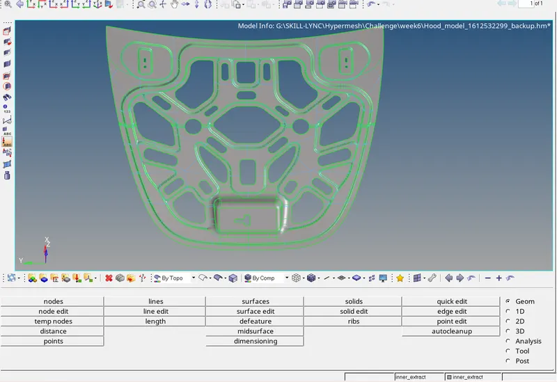
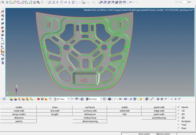
- To check any free edges present, go to wireframe mode and see whether there are any free surfaces which appeares in red colour. Now if everything is clear go for mid surfacing.
- Before mid surfacing measure the distance between the two surfaces with the help of dimensioning and create material and property with thickness respect to that component.
- For midsurfacing go to geometry>midsurface>in the extracting option select offset>set maximum and minimum thickness as 1 and 0 as the measured thickness is between 1 and 0> select the surfaces>displayed> click extract.
- Hypermesh will automatically extract the midsurface withing the few minutes and now check whether all the features are captured properly by turining on both parent and mid surface simultaneously.
- Now setup the mesh parameters for that go to 2D>element cleanup>Edit parameters>change the target element size>change the element type as mixed>ok
- Now setup the quality criteria for that go to 2D>element cleanup>edit criteria>change all the parameters to the required value and click ok.
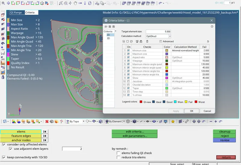
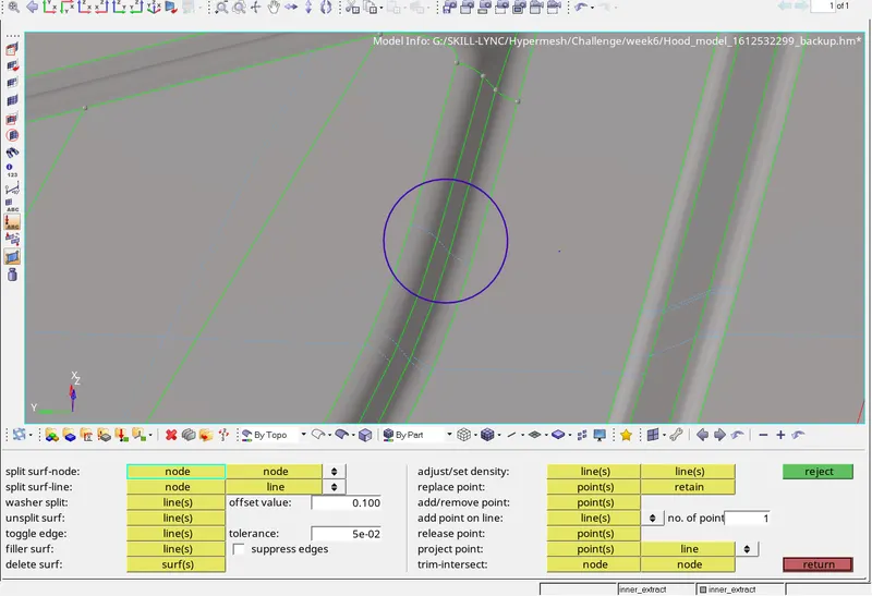
- Now go for geometric cleanup, the area which is lesser than the minimum element size we need to remove that. For that go to Geometry>quickedit>Toggle edge which are not required> remove all the hot points which are not required. Manually check all the edges and surface do repeat the same process.
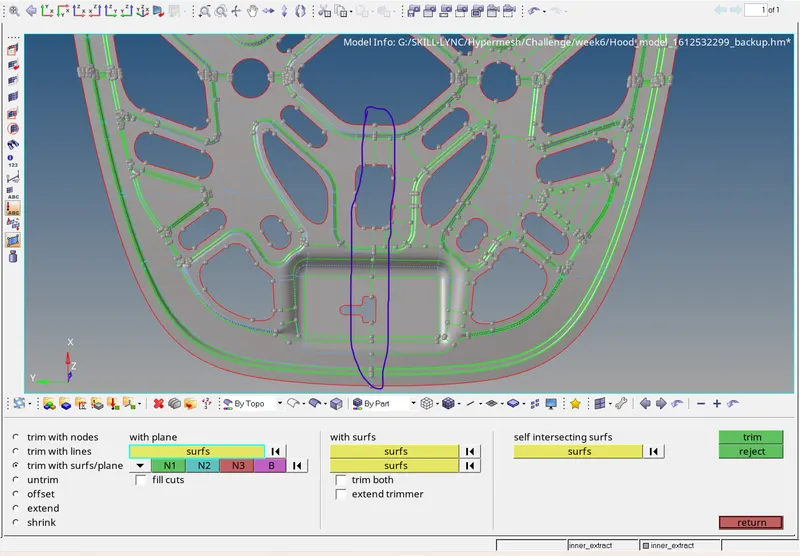
- Now as you observe this component is symmetric about its x axis so made a cut along the mid and delete one half and then do the meshing and then reflect all the elements to the another half.
- For cutting the geometry go to Geometry>Surface edit>trim with nodes or plane>select the mid that we have extracted from parent>select the vectors to define a plane>click trim.
- You can either delete the other side of that component or you can use organise option and keep it as other component.
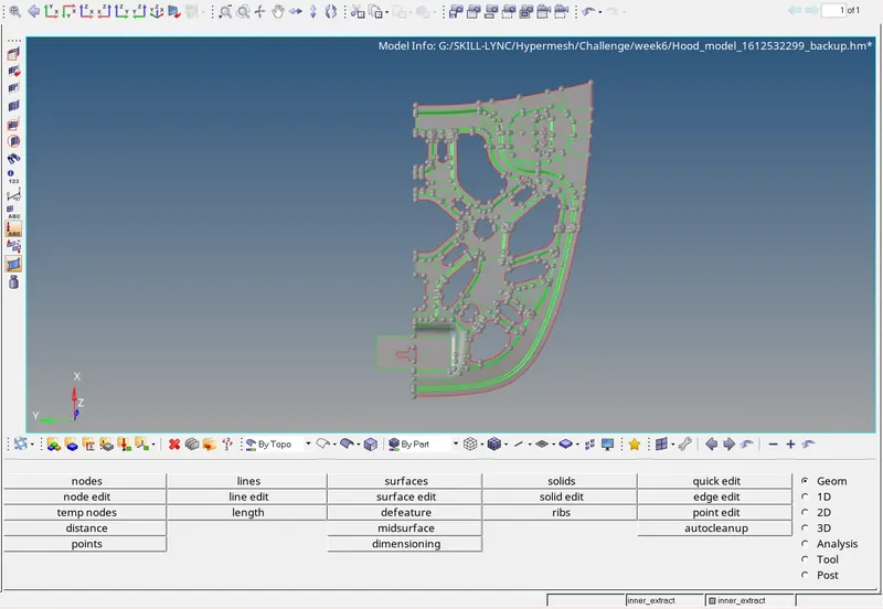
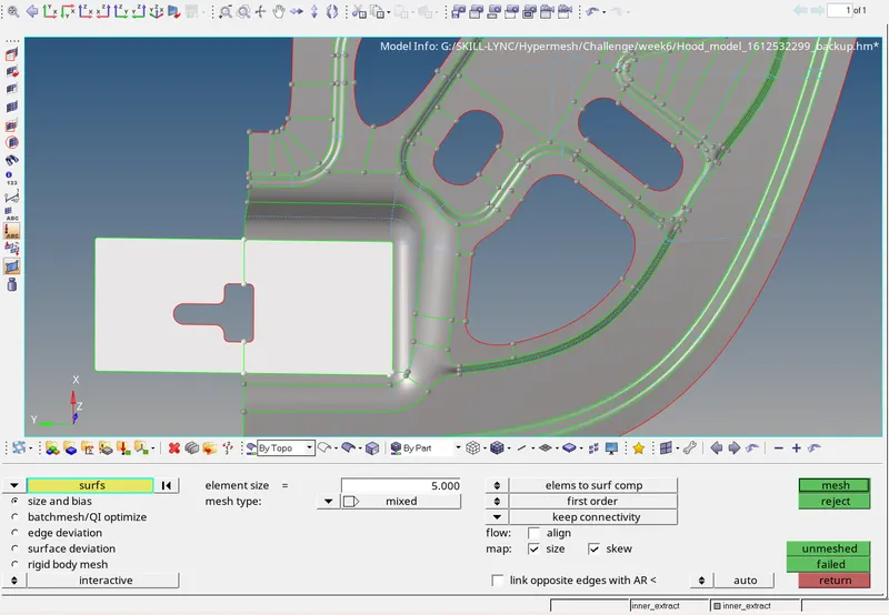
- For meshing go to automesh select the surface manually and do meshing each surface by surface so that you can ge a better mesh flow.
- You can now rebuilt the mesh if it is not proper and now go to quality index, check for element failure and try to clear it with the help of drag tria option to drag and join the opposite trias facing eachother or you can drag it towards the free edge. Similarly we have split, swap, combine, replace, element and nodal optimizaition options to clear the failure element.
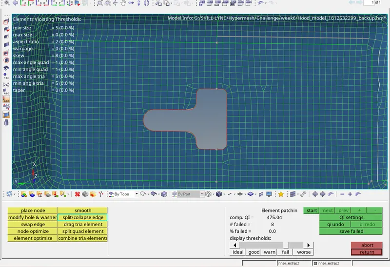
- To identify and view only the failure elements, click save failed and go to mask option click elements>retrive>mask>reverse all. Then you can unmask the elements up to 1st degree and we work on the failure elements.
- Once you done clearing the failure elements and correcting the mesh flow, you can now reflect all the elements to the other side. For that go to tools>reflect>elements>displayed>duplicate>from current element>Select the vector to define a plane>hit reflect. The reason why we are duplicating the elements is because if we are not duplicating the elements it we reflect the original elements to the other side. And there will be no elements in previous side.
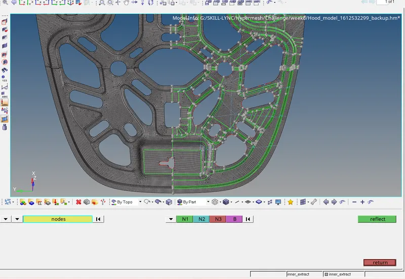
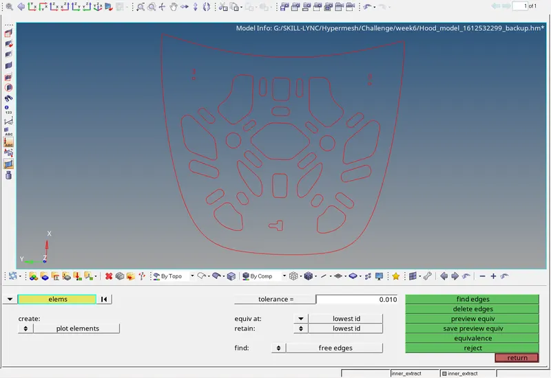
- After reflecting as you see the elements are not pasted at the junction for checking that go to tools>edge>find edge>now you can see the edges at the junction. To auto paste all the elements in that junction go to Tools>edges>select the elemets at the junction>give the tolerance value(the max tolerance value should be less than 80% of the minimum element size )> hit preview equivelance>click equivelance.
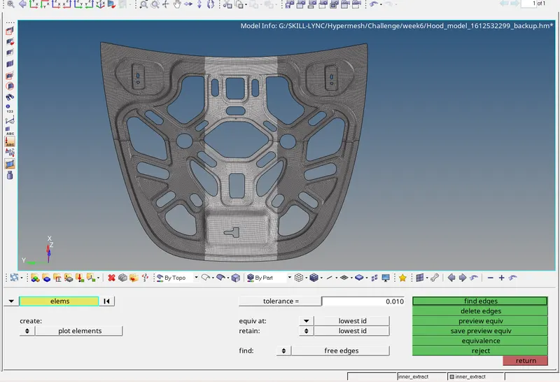
- Now go to tools>edges>find edges> to see the free edges present. As you observe there is no free edges at the junction and all the remaining edges are proper.
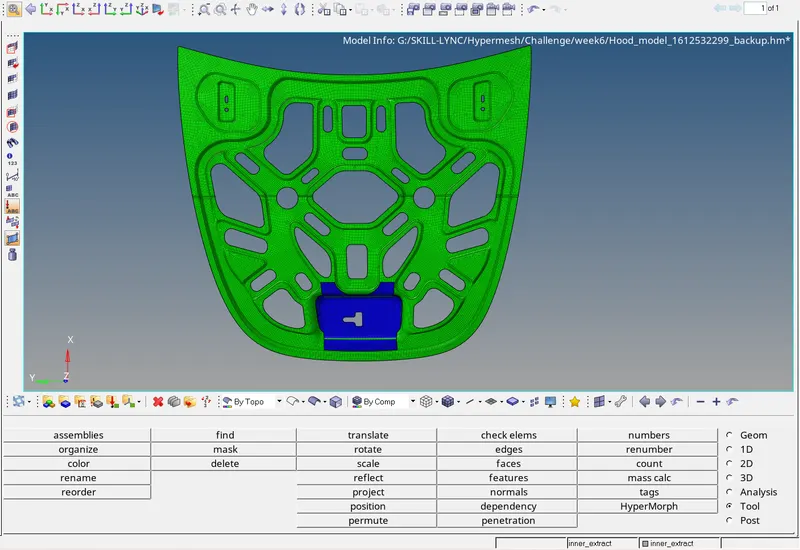
- Similarly work on latch_reinforcement component and the final model look like as shown below.
RESULT:
Thus for the given component the extraction of midsurface and meshing that based on given quality criteria is successfully done.