Extracting Mid-surface and Meshing on HOOD by using Hypermesh
AIM
The ultimate aim of this challenge is to perform the mid-surfacing and meshing on the given automobile BIW component 'HOOD' as per the industrial standards of quality criteria by using HyperMesh software.
GIVEN DATA
HOOD:
Hood is the Automotive component, which is located in the front of the car and cover's the engine. It is the hinged cover over the engine of motor vehicles. Hood can open to allow access to the engine compartment or trunk on rear-engine and some mid-engine vehicles for maintenance and repair.
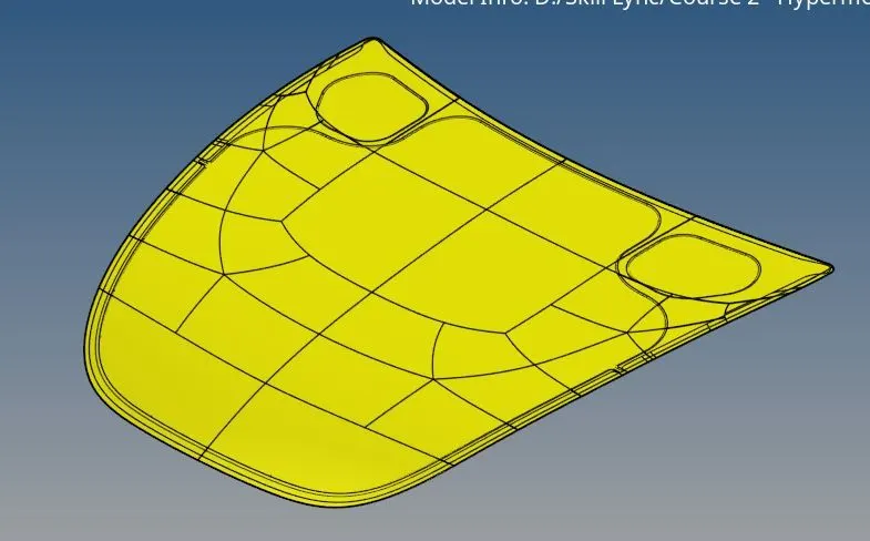
Parts:
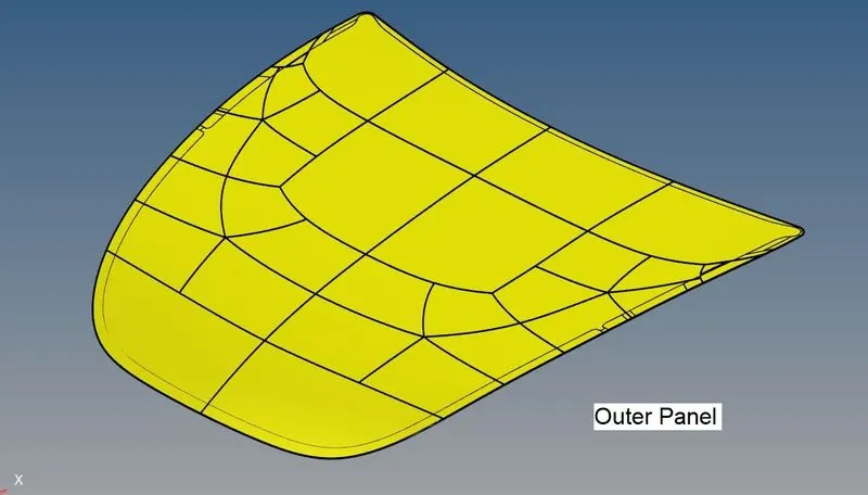
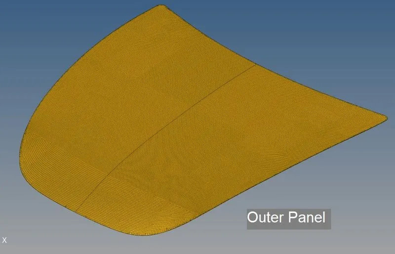
- Outer Panel
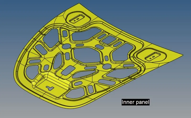
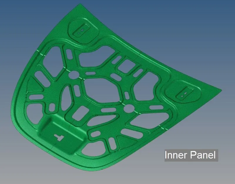
- Inner panel
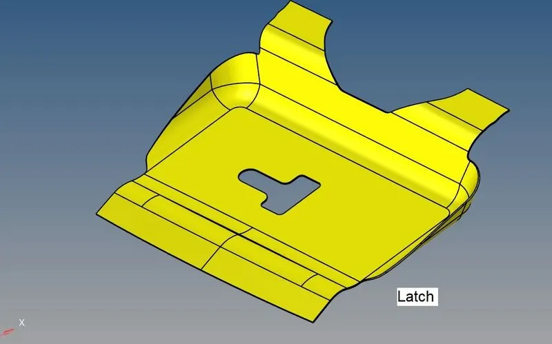
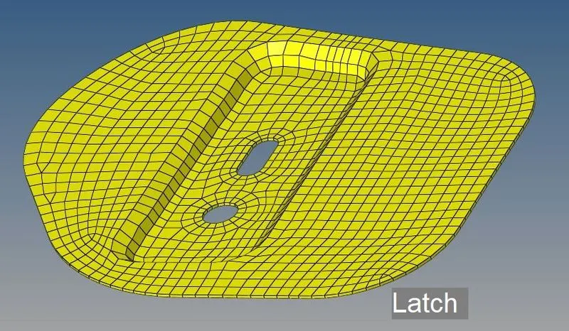
- Latch
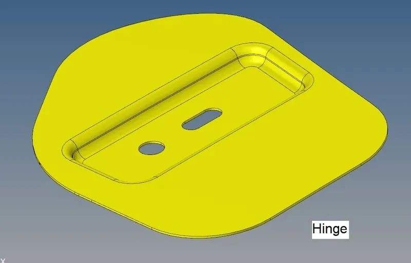
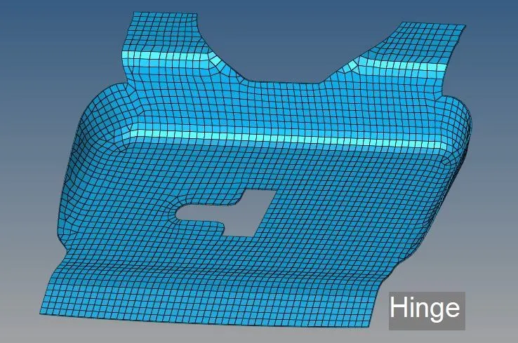
- Hinge
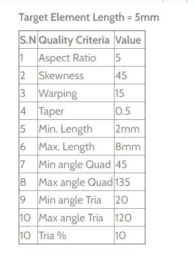
Quality criteria:
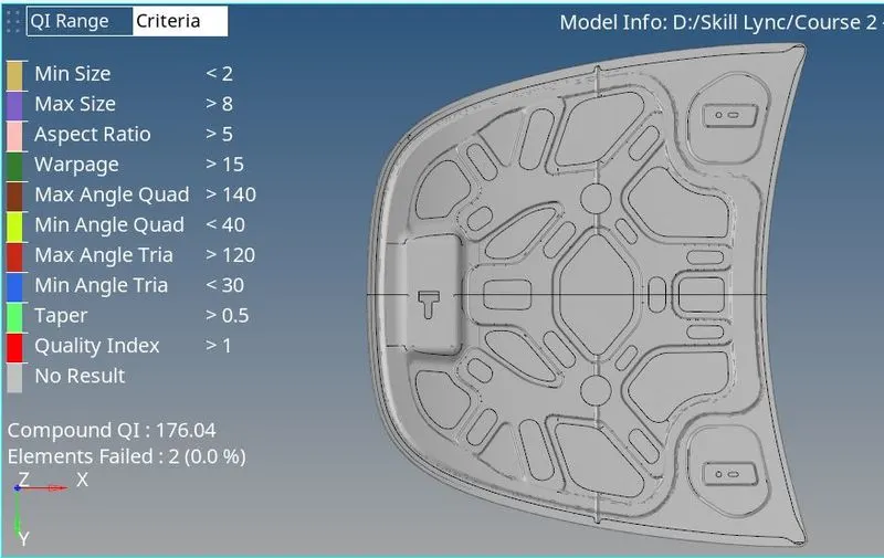
Mesh the entire component as per the given Quality criteria mentioned below,
PROCEDURE:
👉Importing the file:
- Import the geometry of the given model as Stp file by using the tool as import geometry
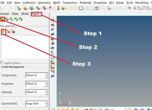
- Import >>> Import Model >>> Select files
- Change the color geometry mode from Auto to By Topo
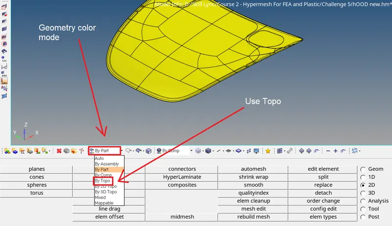
- We select the By topo method because it is the handy option that is used to identify the free edges, shared edges, T-Junction, and Suppressed edge
- Now, clean up the solid part If any present in the Geometry
👉Mid-surfacing:
- It is a technique for creating a simplified shell representation of a solid model. Midsurface modeling can reduce the computational expense of analyzing a complete sold model when a shell model with a defined thickness and fewer details is suitable for the required analysis.
- Geom >>> Mid-surface >>> Auto mid
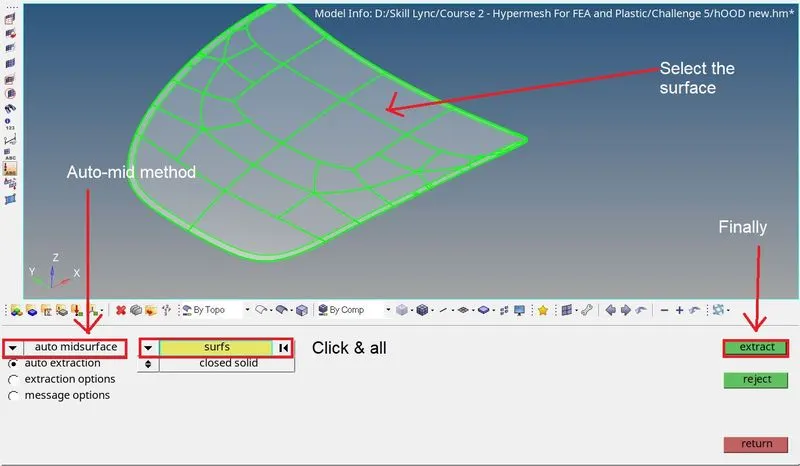
- Select the surface and perform the mid-operation to get the middle surface
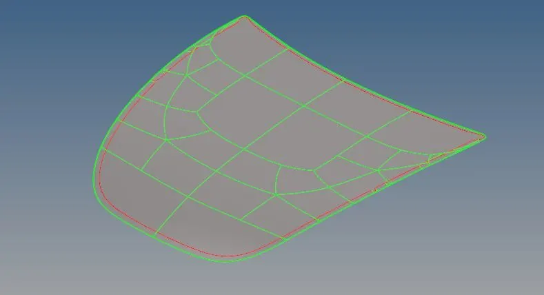
- Perform the same method for every part in the HOOD
👉Auto cleanup:
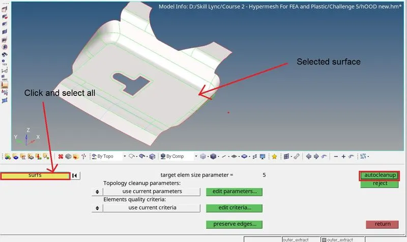
- Auto cleanup is the handy option, which is used to remove the unwanted lines in the surface and removing the small surfaces by toggling the edges and making the washer cut the hole areas.
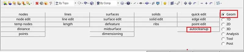
- Goem >>> Auto cleanup
- Select the select by clicking the 'all' option for instant selection
- Do the same thing the remaining parts
Organize:
Organize panel is used to re-organize the database by copying or moving data(entities) among collectors, includes, or parts.
- Tools >>> Organize
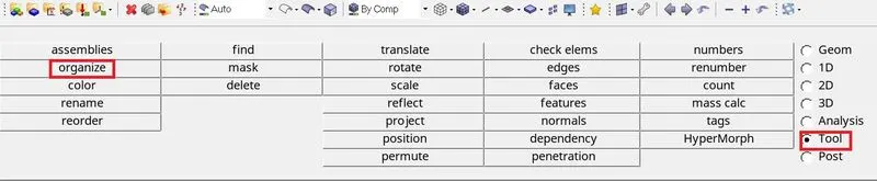
- Organize >>> Collectors >>> surfs
Select the surface and choose the component to assign and we can change color as per the wish
👉Meshing:
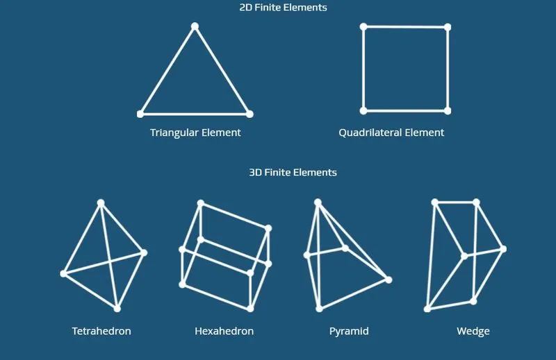
Meshing is a part of the simulation process where complex geometries are divided into simple elements that can be used as discrete local approximations of the larger domain. The mesh influences the accuracy, convergence, and speed of the simulation.
- Automesh option is used for meshing a surface with 2D elements
- Change Geom mode as 2D in the Mainmenu bar
- Then select the Automesh option
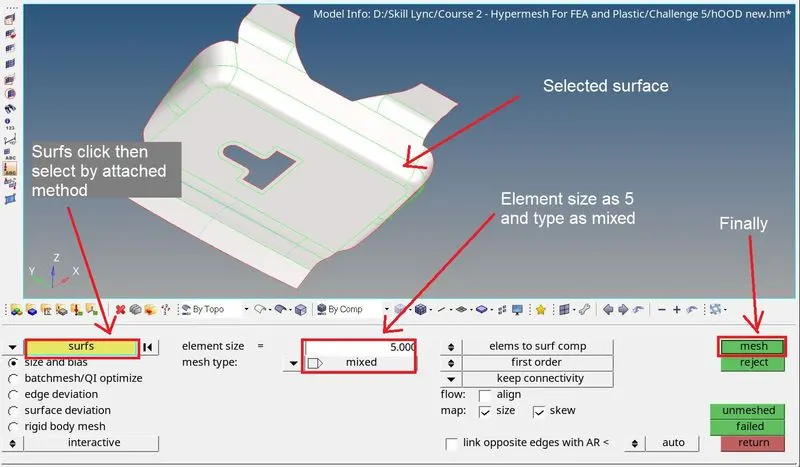
- Click the surf option and select the 'by attached' option
- Input the mesh element size as '5' and type as 'mixed'
- Then check once whether all the inputs are correct
- Then click mesh to perform the meshing on the component
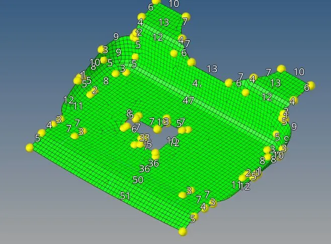
- We can make some changes in the mesh by using some options like Automesh, element clean up, quality index, element edit, and more
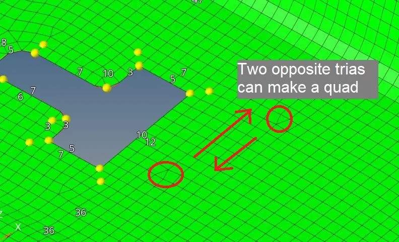
- Here in the above image, we see there are opposite trias are available. so that should be bad mesh,
- For making changes, we have to make the opposites trias as a quad and it's possible
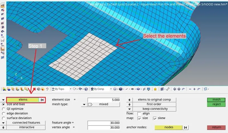
- By using the element edit option, we can split, combine, and create the element as per our requirements
- 2D >>> Element edit

👉Quality criteria:
Quality criteria are the specific element that will be selected, tested, and measured in order to confirm that the quality objectives have been met. The shape of elements in FE analysis must be distorted by their ideal shapes when meshing the irregular or complex geometric shapes.
- Tool >>> Check element >>> input the given criteria details

- Then Go to the quality index
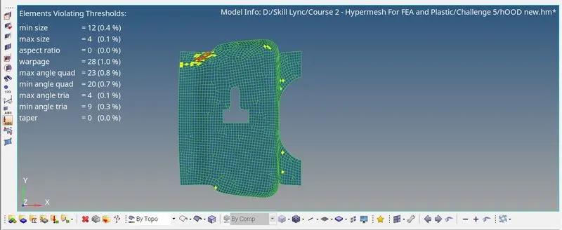
- Perform the element clean up with the help of tools like Drag tria, Split tria, split quad, element optimizes, place node, and more

- By using the above tools, we have rectified all errors
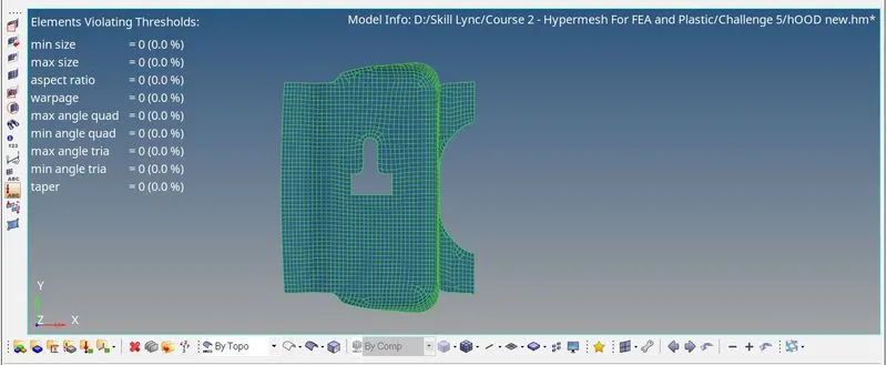
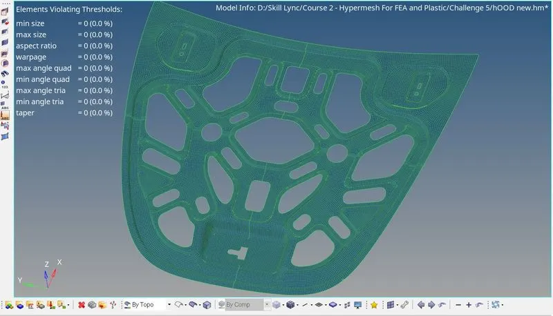
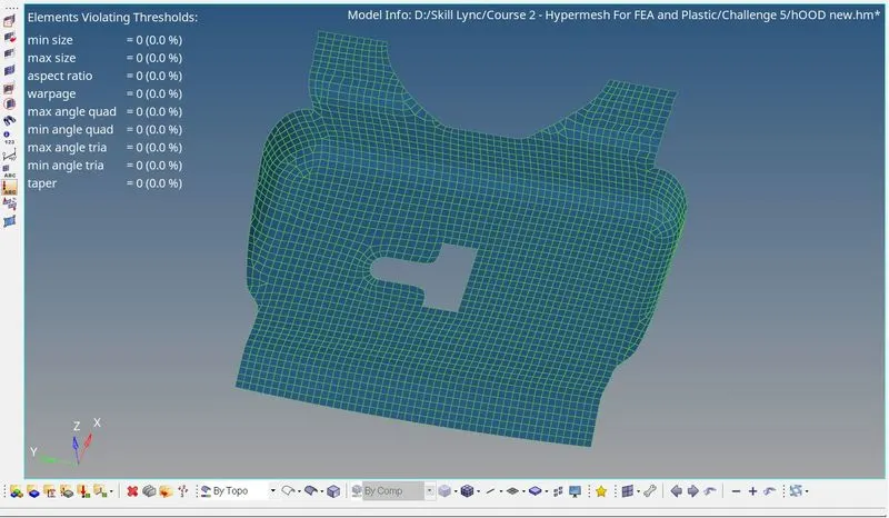
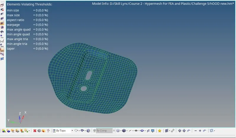
- Remove all the violating threshold, then only the FE is ready for the next step. But some very critical area it has been accepted for some failures
1.Inner panel:
2.Outer panel:
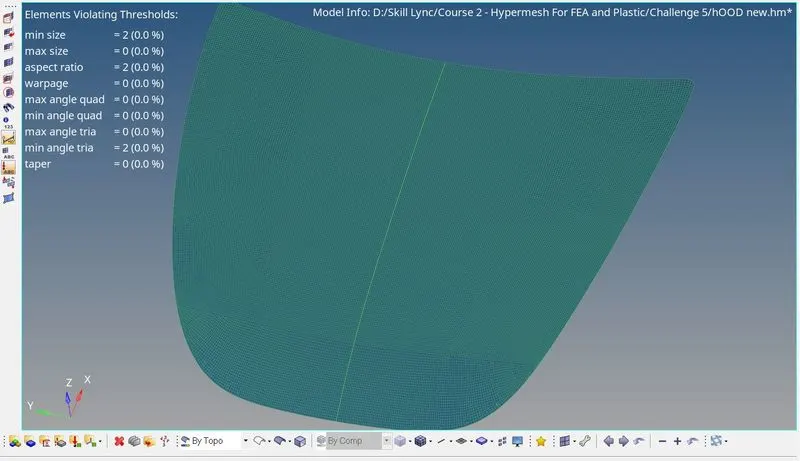
Note:- Here, some quality error has not been solved, but that's not a big issue. If we try too hard to solve those issues then that will disturb the model.
3.Latch:
4. Hinge:-
👉Assign Thickness:
For the model,
Input the thickness value in the property tab of each component as follows,
- Inner Panel - 0.75mm
- Outer Panel - 0.75mm
- Latch - 1.2mm
- Hinge - 1.2mm
Then, Change the 1D traditional representation element into the 2D detailed element representation in the display bar.
RESULT:
Mid-surface extraction and meshing on HOOD have been successfully created as per the quality criteria by using Hypermesh.
Mesh in separate parts:
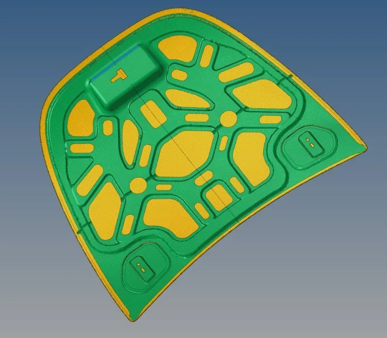
The FE model has been ready for the next process:
Google Drive link:
https://drive.google.com/file/d/1qgdGA0RRTegU2CynYQKSqKBJkwL05yXo/view?usp=sharing