Meshing on a Automobile body component "HOOD"
AIM:
The main objective of the project is the given sheet metal component HOOD assembly has to be meshing for structural analysis using the ANSA (Automatic Net generation of Structural Analysis) software for solving the issues and improves the quality of the component to make the product safe. In this project we applied some quality criteria like Average, minimum length, maximum length, warpage and many more.
FORMULAE:
Here we using very simple formulas during applying the quality criteria and it’s already programmed in the ANSA software. The formulae are,
- Aspect ratio, max
- Warping angle, max
COMPONENTS:
The Car hood is a metal part which placed in the front of the vehicle and it’s cover the engine part. They are having several parts such as,
- Outer panel
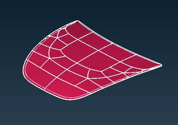
- Inner panel
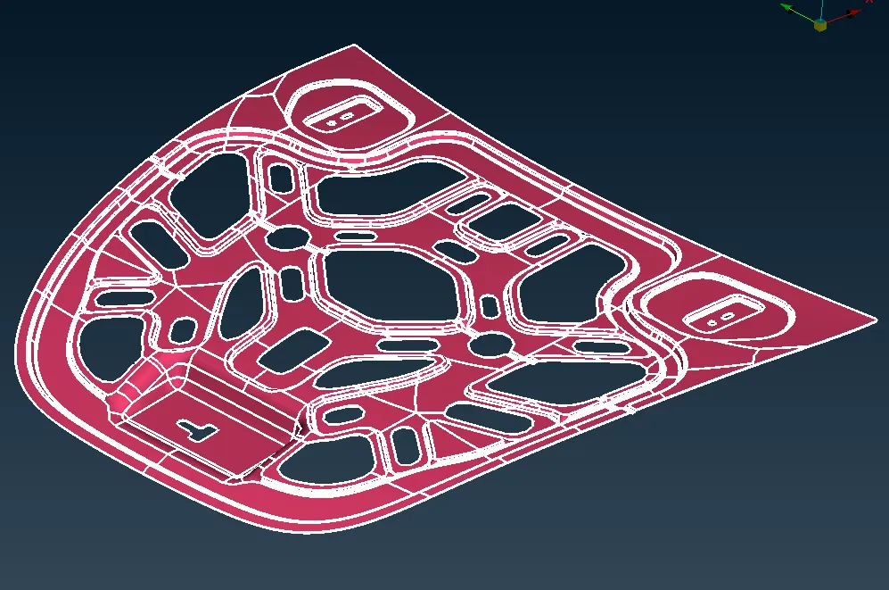
- Latch rod
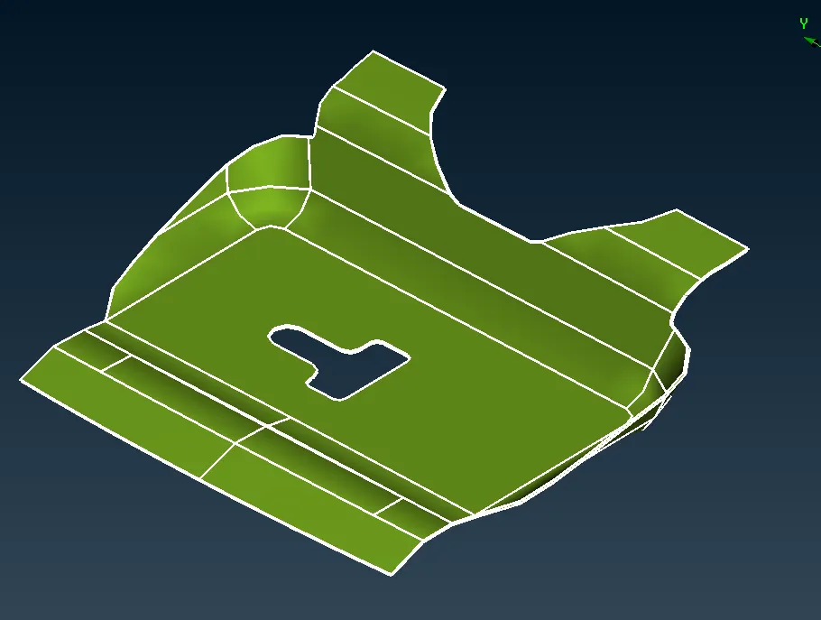
- Couple of Hinge
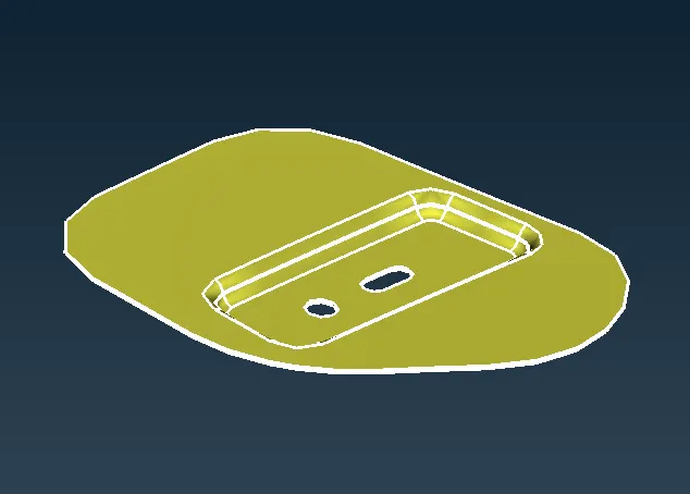
PROCEDURE:
- Open the latest version of ANSA software in your system.
- Import the given sheet metal cad geometry file (.step) in the ANSA, it was automatically changed their file extension into ANSA file(.ansa).
- Identify the topo errors present in cad geometry by the way check > geometry present in the top.
- The topological errors are notified as single con, triple cons , cracks, overlapping faces and many more.
- Understand the reason of the error and perform the actions to resolve it.
- Material identities(MID) and part identities(PID) should be set before doing the meshing operations.
- Extract the middle surface of the geometry, they are several ways to achieve it like manual mid-surfacing(faces>offset) and automated one(faces>mid.surface).
- Change the module (topo – mesh) and perform the 2D mesh with your favourite mesh operations like free mesh, best mesh, spot mesh etc.,
- Check the mesh quality with the given quality criteria and resolve if any error occurs.
Importing :
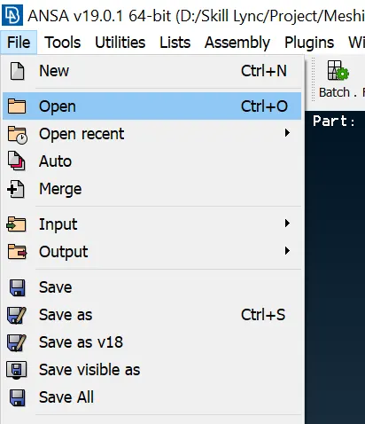
Open the latest version of ANSA in your Pc/Laptop. Import the cad geometry files through ~ file > open or ctrl + O
Geometry check :
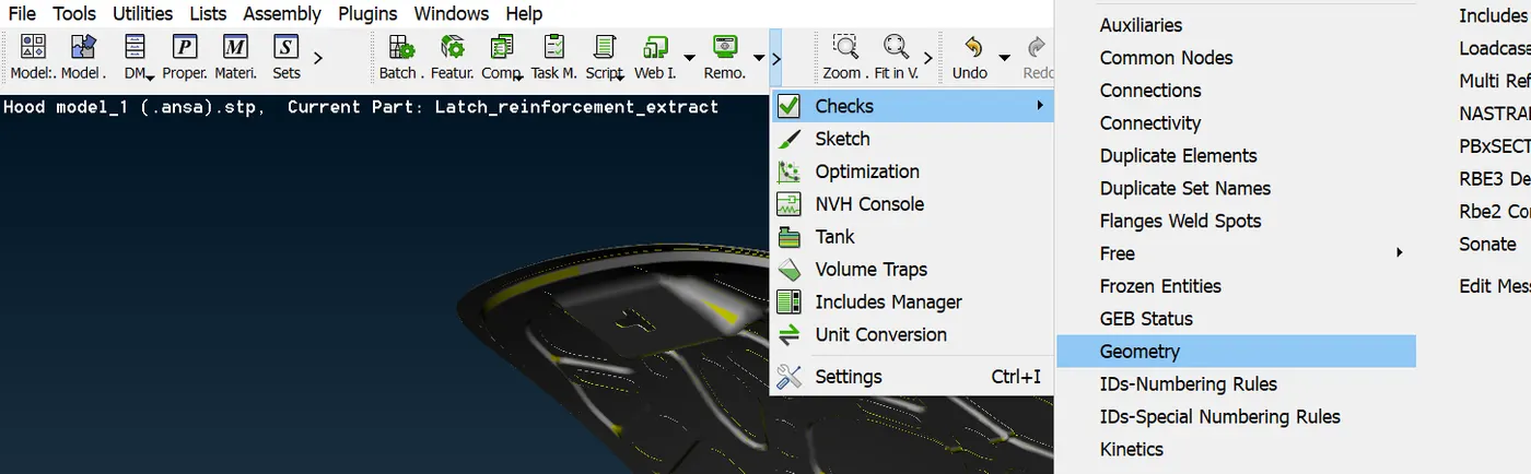
Topological errors has to be checked for the given Hood Assembly component through the following steps ~ Tools > checks > geometry
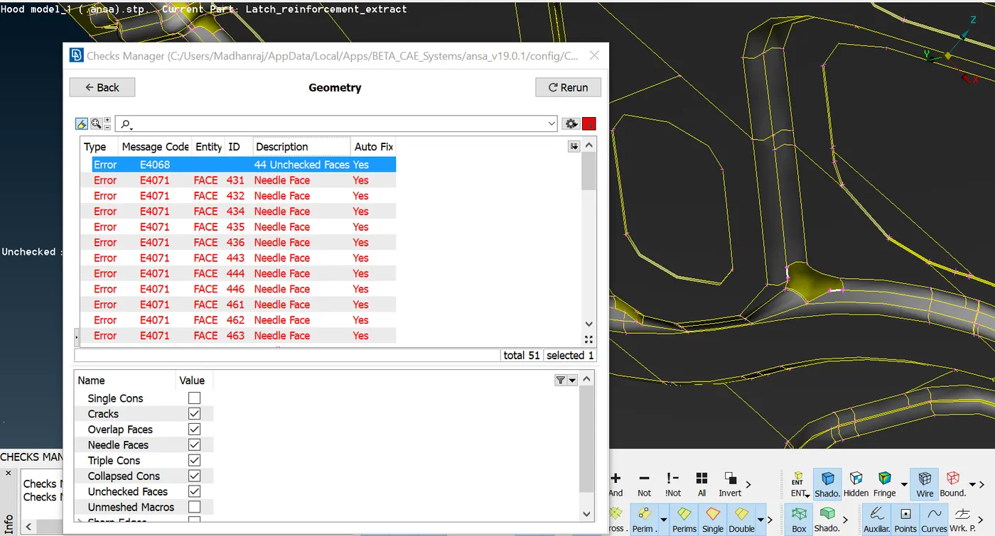
After checks the geometry,
If there is any error is present then the check manager will shown the error with its type, message code, entity, ID and reason like cracks, triple cons, collapsed cons, needle face etc., and also its shown if the error has been cleared by auto fix itself that's a great advantage for us.
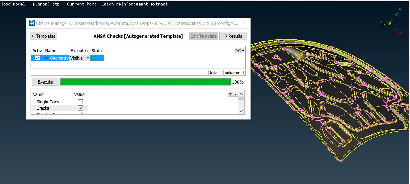
If the error has been able to clear with the use auto fix then,
we have to done with ~ ctrl + A to select the whole error then right click the mouse and fix it.After the probelm has been resolved then the check manager will shown the execution is 100% like below.,
Mid - Surface :
Mid – Surface extraction is the method to simplify the meshing operation. If we didn’t use the mid surface then the simple geometry of meshing process can take very long time to achieve the proper result.
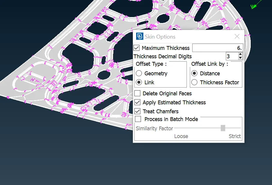
NOTE :- Please untick the option [Delete Original Faces]
Mid - surface extration is creating a shell in the middle of the outer and inner surface of a solid model or geometry. It converts the solid geometry into a thin shell, which reduces the time taken for meshing by reducing the areas to mesh.
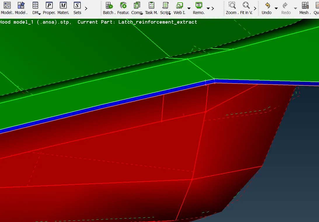
In this above image, the red indicates the bottom surface and the greeen indicates the top surface and the blue indicates the thickness of the geometry.The ANSA automatically takes the offset value by calculating the blue surface.
Assign the offset value of the shell, before assigning check the thickness value of the sheet metal ~
It is mandatory to check the mid surface is correct in quality because it may damage through some defects like crack and discontinuity in the geometry.
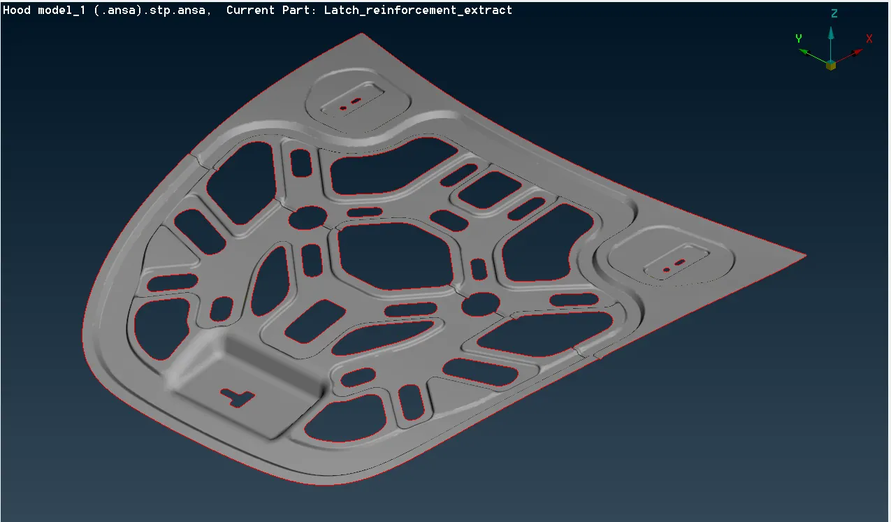
This was perfect mid surface of the inner panel.
In some ways are there to check the mid surface has been performed well, choose the mid surface a then merge the parent surface by way of getting it through PID manager bar.
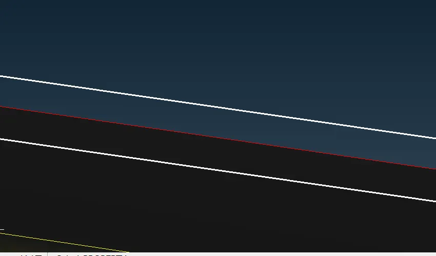
The both white layers are the parent surface of the mid surface, we can rotate (ctrl + mouse left click) the object and verify that the mid surface has been generated correcrtly.
Now again do the geometry checks for mid surface like its parent and under the probelm and fix them all.
Set PID & MID & Thickness :
Setting PID (property ID) and MID (material ID), which is most important thing that we don’t forget to perform ~ Topo > Module buttons > Faces > Set PID
First we select the surface and property bar will open like this
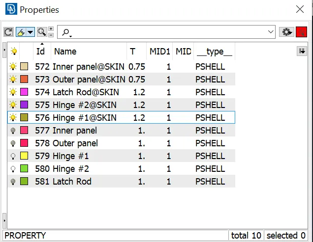
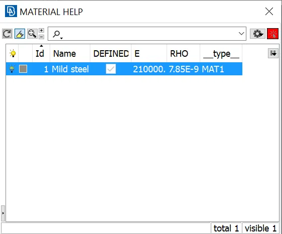
We can devolpe the mid surface every part and assign the property Id to all. Double click the property of the inner panel to get the detailed property of the part.'T' which indicated the values of the thickness and 'MID 1' which is nothing but it indicates the material Id ( shift +?) to get the material details be sure we need to get the tick in the box.
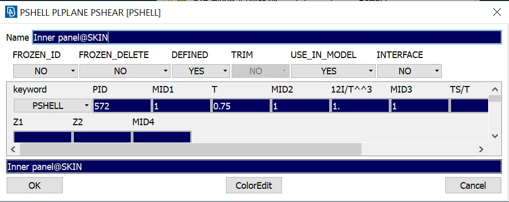
here, we can assign the thickness of the material in the tab "T"
for Inner panel and outer panel ~ 0.75 mm
for Latch and Hinge ~ 1.2 mm
The material mild steel has to been assigned for all the parts.
Meshing:
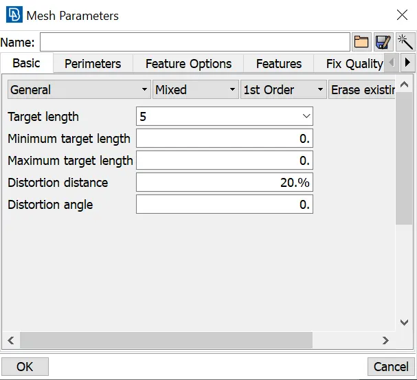
After transforming the solid part into the shell to be created, assign the target element length as 5mm and the type is mixed element.
Quality creteria:
Assign the meshing quality criteria(F11) that’s given in challenge.
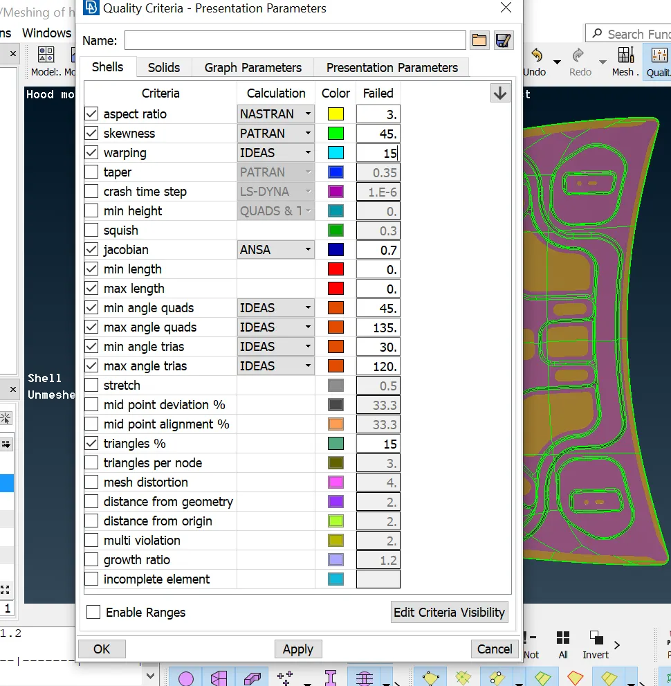
The mesh elements has been created by mixed that means containing both trias and quads.If we trying to meshing the entire element in a single process which will violating the surface, so we need to perform the action by dividing the parts into small macros.
The length has to been assigned as,
Perimeter and macros are both as 5 mm.
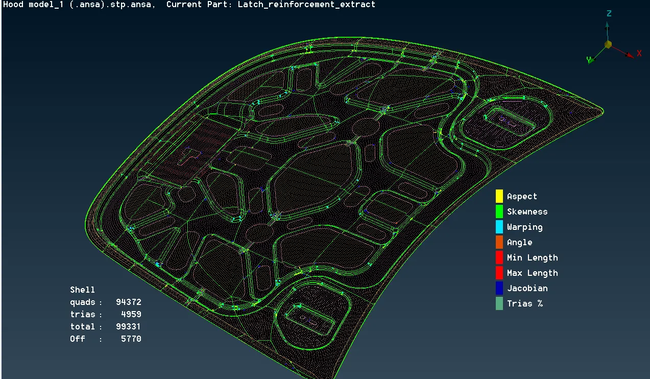
Here the above image says that the meshing is very violating and we need solve the issues that are found. when the quality creteria has not met with the requirements then that has been indicated as off, here there are 5770 off are present we need solve this into zero for a safe meshing.
we can choose our preferences like spot mesh, best mesh etc., after meshing use re-construct the mesh that will give the smooth mesh.
Elimating the errors like minimum and maximum length, skewness, warping, angle, jacobian and trias % by using split, join and swap comment.
Things to be avoided:
- Try to avoid the trias at construction line.
- Avoid the Rotating quads.
- Avoid the trias present at the free edge of the circle or a border.
- Avoid the two opposite trias very near.
Things to be Followed:
- .Keep the mesh flow smooth
- Keep the trias in same direction
- Keep the Construction lines that’s will indicates the shape of the shell
- Keep the off as zero.
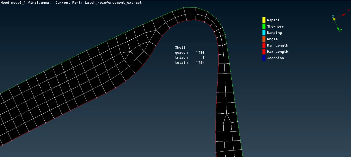
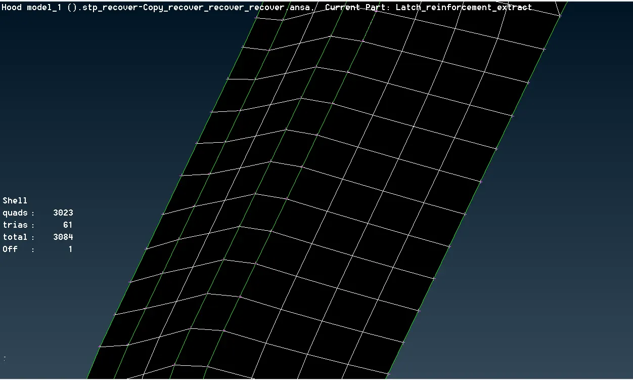
Remove the off by using re-constructing the mesh and smoothing the mesh, In some areas we need to perform with split, swap and join and some places we need to use move and paste comment present in the grids.
And finally perform the mesh with all criteria and flow thats was good enough then complete the process by releasing the elements.
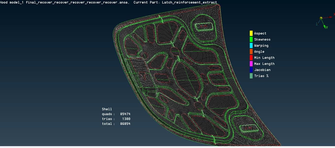
Note: Element release is a one time process.
Learning Outcome:
In this challenge, I learned lot of thinks such as,
- About ANSA software
- Meshing and its property
- About HOOD
- Parts in the Hood
Conclusion:
For beginner like me, it’s little bit tough to solve the error that’s found during the meshing and understanding the hood which will take some time.
During meshing, faced lot of challenging operations that are create a construction lines that’s have been in a critical area with the required quality criteria and also the shape of the model has a good view without changing its original shape.
Here some limitations of the project is always we need to have a look on meshed areas while doing mesh in another area.
Final mesh hoood assembly
https://drive.google.com/file/d/17wQZZXX8cEpwGdKWXx9cOK4JGKDlkfuq/view?usp=sharing