Week 6-Meshing of Hood Challenge
OBJECTIVE-
- Generating midsurface and geometry clean up on the component.
- Generating mesh on the component with low tria concentration and proper mesh flow.
- Model should pass all the given quality parameters.
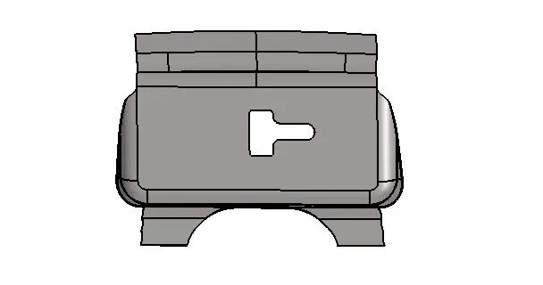
Parent Component-
- HOOD-
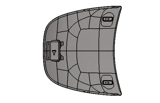
Sub Components
- Inner Extract
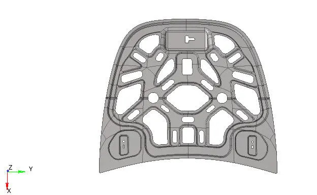
- Outer Extract.
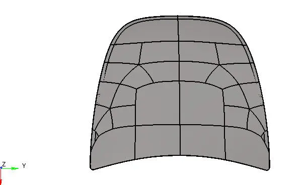
- Hinge Reinforcement.
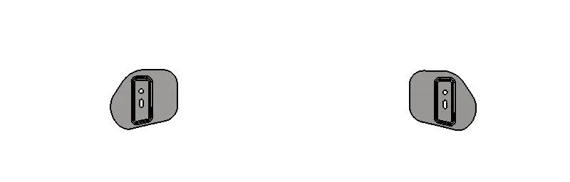
- Latch Reinforcement.
PROCEDURE
1. Extracting the midsurface.
- Extracting the midsurface of the component is done separately for getting proper midsurface and also to make problem easy.
- Midsurface is the 2d representation of the 3d object.
- The extraction of a midsurface should be a exact replica of the parent component.
- After extracting midsurface rename the midsurface by their parent name so that there will be no confusion and also assign different colour to them.
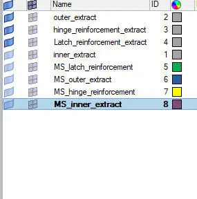
- For extracting the midsurface go to "geom" then select "midsurface". After that select option as "auto midsurface" and give the extraction option as "offset+planes".
- Select the component one by one and under the surface option select "displayed", the entire component will get selected and then click "extract". The midsurface will get extracted.
A.Midsurface of inner extract.
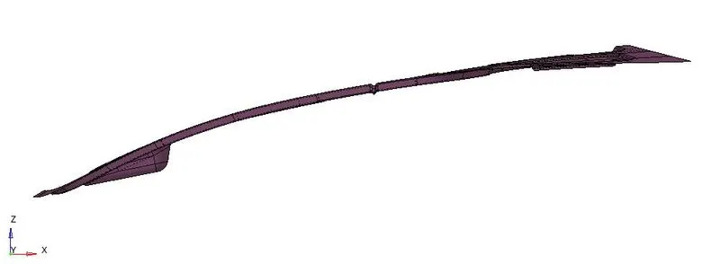
B.Midsurface of outer extract.
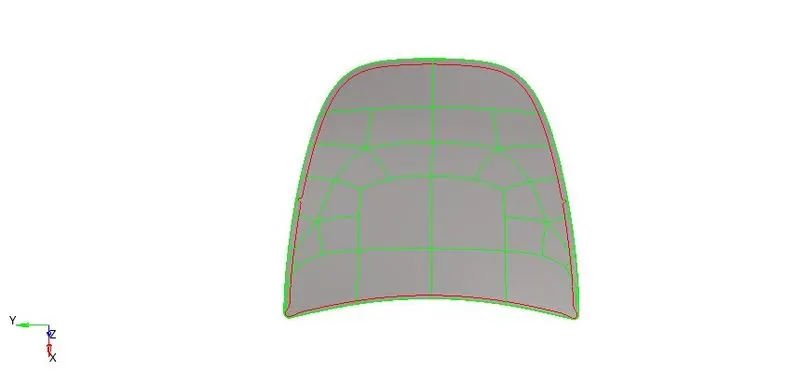
C.Midsurface of hinge reinforcement.
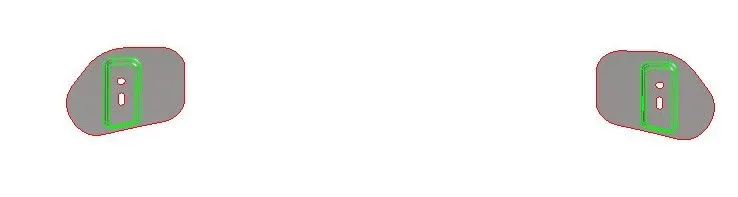
D.Midsurface of latch reinforcement.
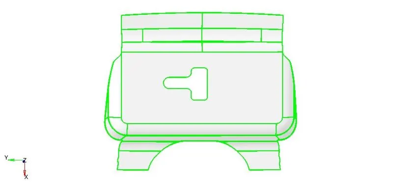
2. Geometry Cleanup
- Geometry cleanup is done before meshing to remove unnecessary points, toggling the edges, supressing/unsupressing the edges, filling geometry, missing and free edges, etc.
- We have to be very careful about the geometry before meshing a particular component. .
- For toggle edges go to "geom" select "quick edit" and then select "toggle edge" option. After that toggle the edges which is not necessary for meshing.
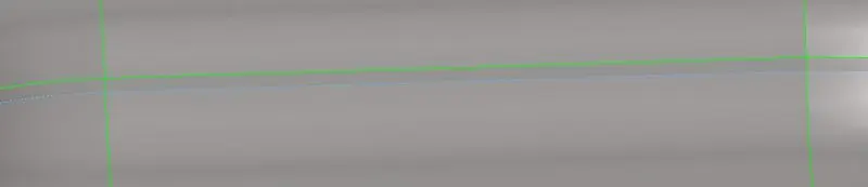 geom>quick edit>toggle edge.
- For removing the geometry which are not proper or damaged, go to "delete" option select the option as surface then select the surface which is to be deleted. After that click delete entity, surface will get deleted.
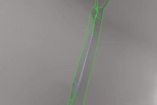 Improper surface.
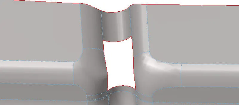 delete>surf>delete entity.
- For rebuilding the surface go to "geom" then select "surface" after that select the option as "rulled". Select the free edge of the deleted surface, the surface will get filled as per the required shape.
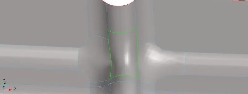 geom>surface>rulled.
- As the inner and the outer extract component are having surfaces which are identical so we can cut the surface into two equal part then delete one part and work with another part. After that by refecting the same to the other side, we can save our time and effort and complete the work. For doing so go to delete option select the surface which are identical and click "delete entity".
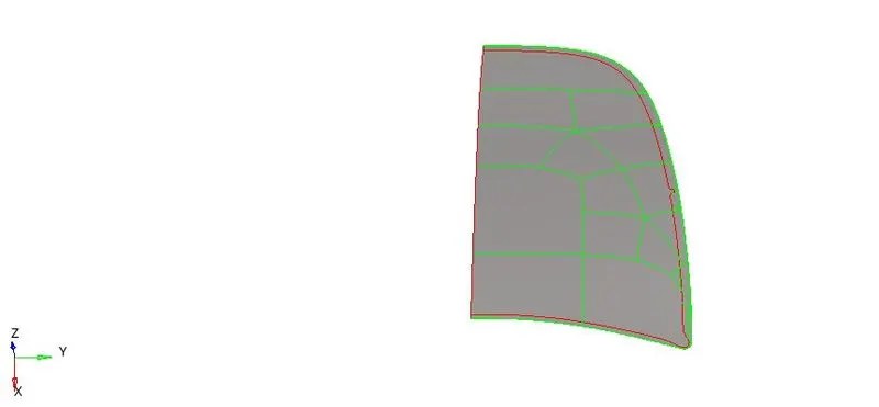
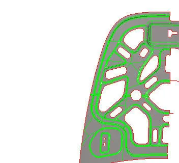 delete>surf>delete entity.
- Next step is to divide the geometry in such as way that it can form a square or rectangle so that in that region mesh will be proper (Note while cutting the surface always avoid the generation of sharpe edges) and also provide "washer split" wherever necessary. For dividing the geometry go to "geom" then select "quick edit" after that select "split surf-node", then select the two nodes from where the geomtry is to be divided.
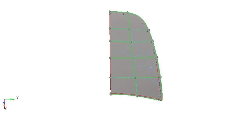 geom>quick edit>split surf-node.
3. Setting Qaulity criteria.
| S.N | Quality Criteria | Value |
| 1 | Aspect Ratio | 5 |
| 2 | Skewness | 45 |
| 3 | Warping | 15 |
| 4 | Taper | 0.5 |
| 5 | Min. Length | 2 Units |
| 6 | Max. Length | 8 Units |
| 7 | Min angle Quad | 45 |
| 8 | Max angle Quad | 135 |
| 9 | Min angle Tria | 20 |
| 10 | Max angle Tria | 120 |
| 10 | Tria % | 10 |
- Element size should be 5mm.
- For setting up the given quality parameters, go to menue bar then select "Preferences". After selecting preferences then select "Criteria File Settings" then enter the quality criteria as per given requirement.
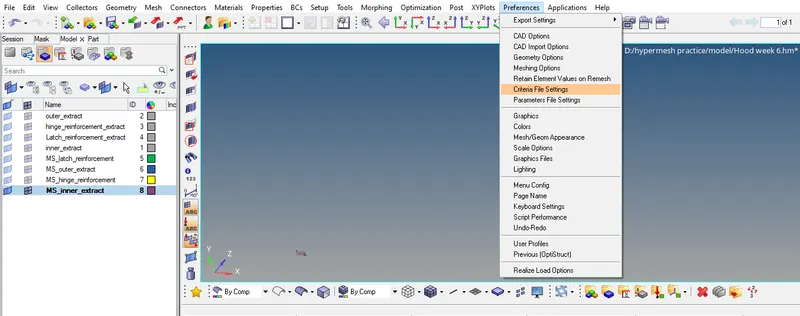
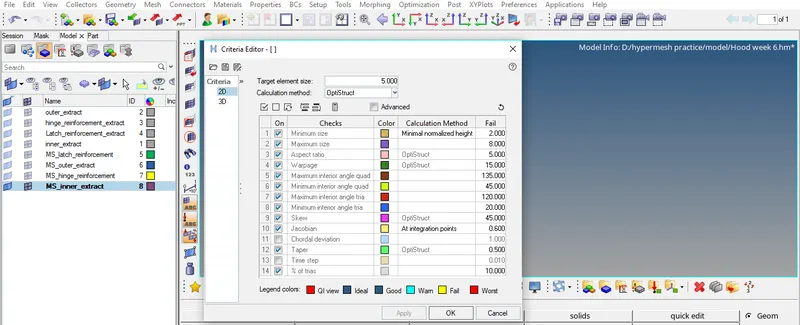
4.Meshing the geometry
- Meshing of a geometry is done separately. Mesh size taken to be "5mm" and mesh type is mixed.
- Meshing in a geometry is done part by part so that there should be a flow in mesh and also the given quality standards should get satisfy easily.
- For meshing go to "2D" then select "automesh". Now in "automesh" select as "surf" and give the element size as "5" and type as "Mixed".
- Select the surface from the display area and then click "mesh". Element in the selected region will get created.
- There are few check which we have to take into consideration which are, tria management, no tria in the corner, no trias in the opposite direction, no back to back trias, no rotational quads.
- After meshing we have to check if the given parameters and quality criteria is getting satisfied. If not then we have to perform few operation.
- For checking the quality criteria there are two method, 1st to check with the help of "quality index" and 2nd with "check element".
- For checking with the help of quality index, go to "2D" then select "qualityindex". In the quality index on the left side there are few option to decide how precisely a quality criteria must be check, so we can set the display thersholds starting from ideal to worse. On the right side there are few tools with the help of which we can make or mesh proper.
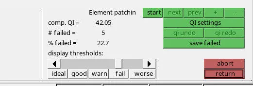
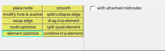 2D>qualityindex.
- For checking with the help of check element, go to "tool" then select "check elems" after that select 2d. The given quality criteria such as aspect ratio, skewness, warpage, etc tools will get displayed. We can check for the selective criteria one by one and can resolve the problem accordingly.
 tool>check elems.
- For removing the error we can remesh the element by going to "2d" then "automesh" then selecting the option as "elems".
- We can remove the opposite trias by just draging then and combining so that it get combine and form quad. For that we can go for the option "drag tria element" from the "quality index" or we can just remesh the elements by doing "automesh".
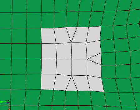 Removing opposite trias.
- After dragging trias mesh flow may get disturb so for getting a proper mesh flow we can use the smooth option. For using smooth go to "2d" than go to "smooth" option, select the elements from the display area and the click smooth. Click the smooth option again and again till the large displacement iteration value turn out to be zero or near to zero.
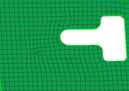 Mesh flow before smooth.
 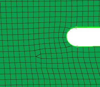 Mesh flow after smooth
- Removing trias from the corner and also removing rotational quad can be done by automeshing those elements.
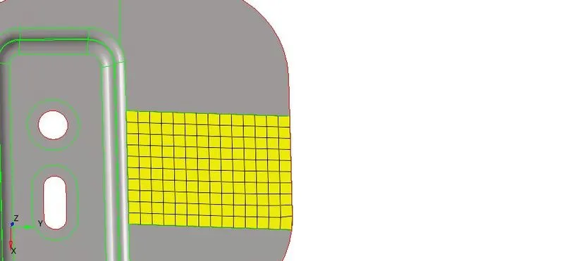
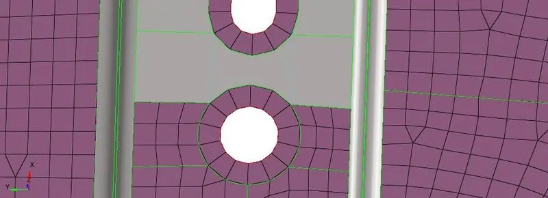 Meshing by spliting.
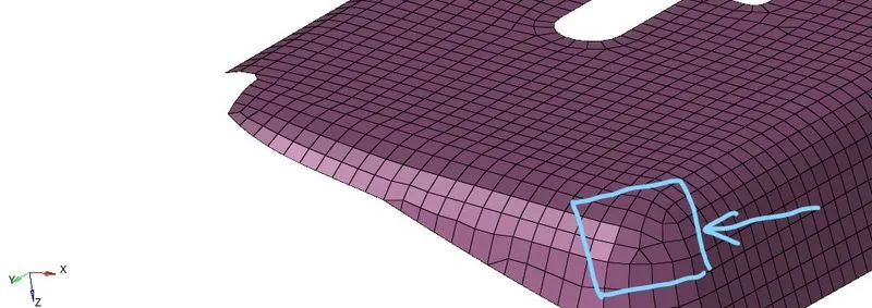 tria management- back to back trias.
- If after meshing somehow due to surface geometry error there might be a gap get generated between the two neighbouring element, to fix the gap go to "Tool" then select "edges". After that set the tolerance value as per the requirement then select the elements from the display area and then click "preview equivalence" after that click "equivalence", the element will get attach.
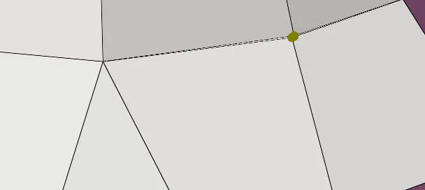 Tool>edges>elements>preview equivalence>equivalence.
5. Reflect.
- After completing with the mesh of the one identical part the same has to get reflected to the other side.
- For that go to "Tool" select "reflect" option. After selecting "reflect" then select the option as "elems", select the entire elements from the display area and the in the element option click the option "duplicate", all the selected elements will get duplicated. After that give the direction "N1" "N2" "N3" & "Base" then click "reflect", the element will get reflect on the other side in a particular given direction.
 Tool>reflect>elems.
- After reflecting the element in the model we have to verify the connection between the elements. For that go to "Tool" then select "edge", then select the whole elements and click "preview equivalence", increase or decrease the tolerance value till the node get highlighted in the model, after that click equivalence. The elements will get connected.
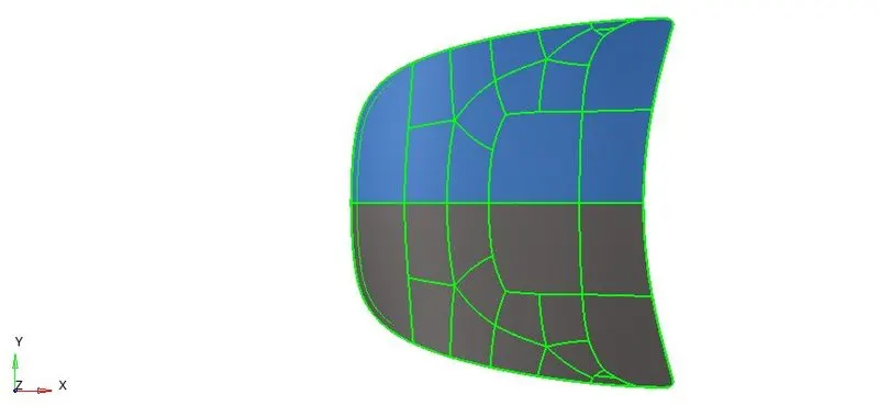 Tool>reflect>elems>duplicate>N1,N2,N3,B>reflect.
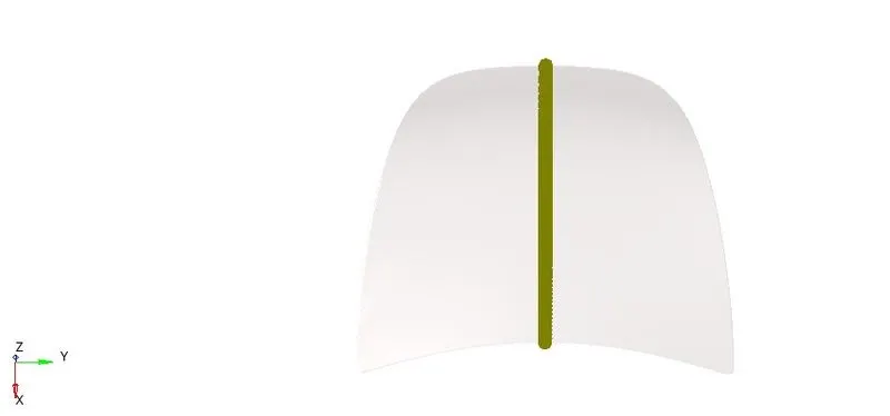 Tool>edge>elems>preview equivalence>equivalence.
- We have to check if any duplicate element is still present after reflecting, for that go to "Tool" then select "check elems" then click "duplicates". If any duplicates are present in the current mesh which is displayed in the display area then the part which is having duplicate element will turn white. Save the duplicate element by clicking to "save failed"
- For removing the duplicate elements go to "Tool" then go to "delete" after that select the option as "elems" and in element click the option as "retrieve" then click "delete entity" all the duplicate element will get delete.
 Tool>check elems>duplicate>save failed.
 Tool>delete>retrieve>delete entity.
RESULTS.
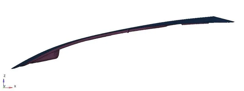
1. Inner Extract
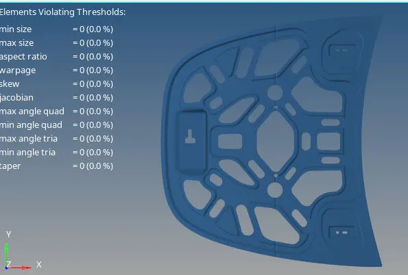
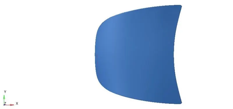
2. Outer Extract
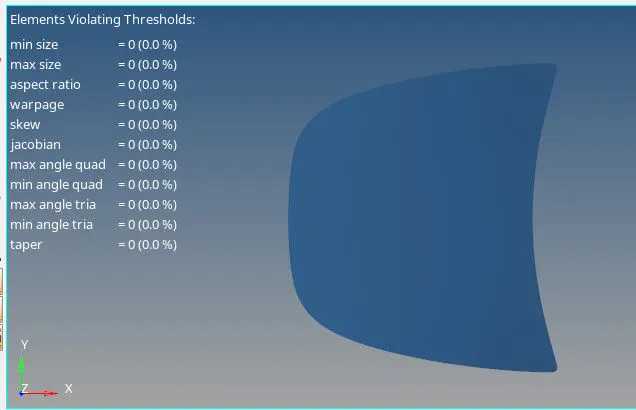
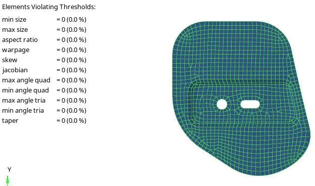
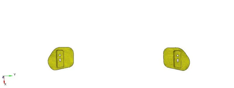
3. Hinge Reinforcement.
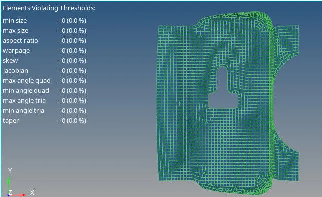
4. Latch Reinforcement
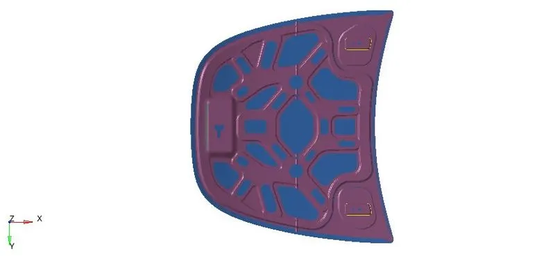
5. Final model.
NOTE.
Due to fine element the count of nodes has exceeded to 100384 and due to the premission restriction the entire model was enable to save. The permission was having restriction of maximum 100000 nodes, so 384 nodes was extra. As hinge reinforcement has two identical part so for saving the model one identical part I have deleted.
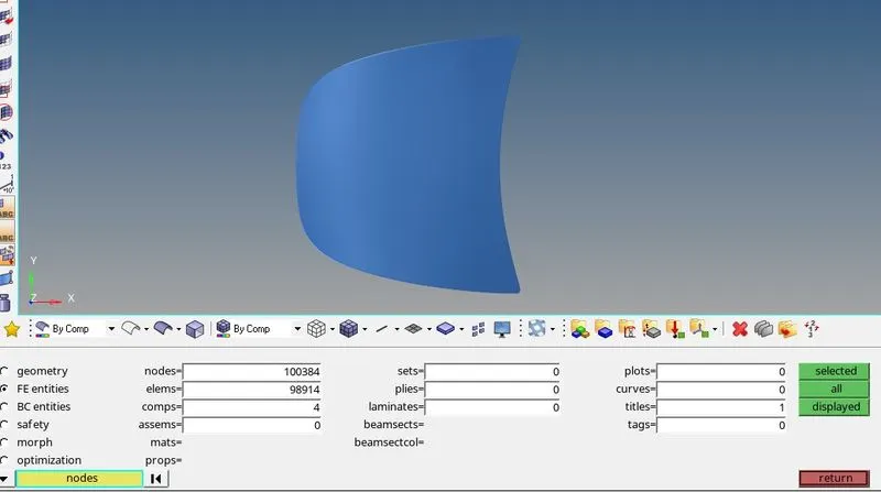 Node=100384
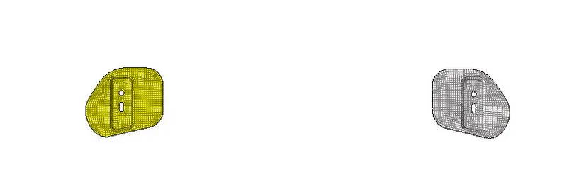 Deleting One hinge element.
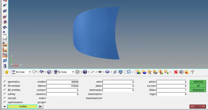 Nodes count reduce to 99058.