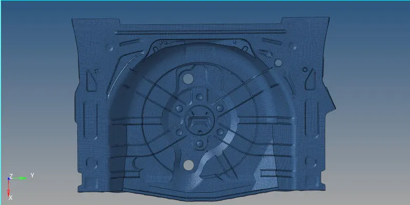
Week 12:Project 2-Meshing of Rear Wheel Holder challenge
Objective-
- Generating Midsurface and performing the necessary geometry cleanup on the component.
- Generating mesh on the component with low tria concentration and proper mesh flow.
- Model should pass all the given quality criteria.
- Assigning thickness to the component.
CAD Model-
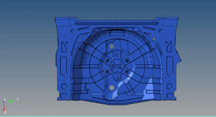
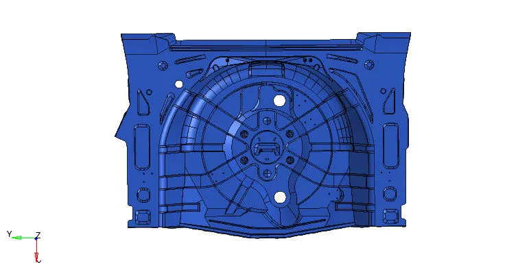
Procedure.
1.Importing the geometry.
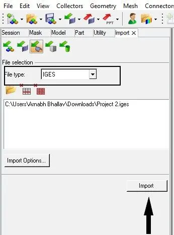
- To import the geometry, go to "tool bar" then select "import solver deck", click "import geometry". As our file type is "IGES", select the file type as "IGES" and the click import.
- Select the option "fit model" so that our model get oriented to the particular plane.
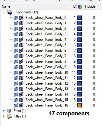
- There are 17 different component in the components section, so we have to organize those 17 component into a single component for that we will use organize tool.
- For using organize tool, go to "tool" then select "organize", under organize select the option as "surface" and then under "dest component" select a particular component in which all the other component is to be moved, then click "move".


2.Geometry Clean up before extracting Midsurface.
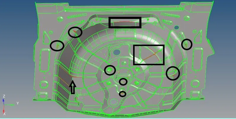
- As it is a complex geometry, we have to go through the entire model properly before extracting the midsurface and do a proper geometry cleanup of the model.
- To examine the geometry properly we will select "by topo" mode from the tool bar.
- Before extracting the midsurface the geometry clean up consist of, replace points, toggling unnecessary edge, spliting the surface, filling geometry, etc. For doing so we will use the "Quick edit" option which is present in the main menue bar under "geometry".

3.Extracting Midsurface.
- Extraction of a midsurface can be done manually as well as automatically. For manual midsurfacing we can use "distance" and "offset" command. Distance option will basically helps us in checking the thickness and offset option will help us to offset a particular surface.
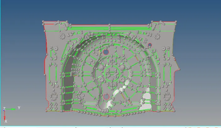
- For the given component we can extract the midsurface automatically by use "offset+planes+sweeps". For that, go to "geometry" under that select the option "midsurface", under midsurface select the extraction option as "offset+planes+sweeps", after that select the entire surface by clicking "displayed" option under surface and then click "extract".


4.Geometry clean up after extracting Midsurface.
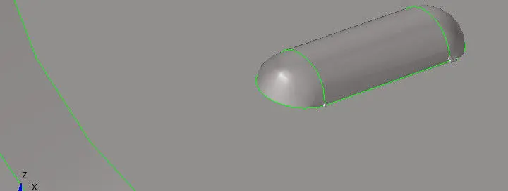
- First step is to remove the buttons using "delete" option, and then fill those part using "spline/filler" option. For deleting the surface, go to delete option and then select "surface" select the button which is to be deleted and then click "delete". For filling surface, go to "geometry" then select "surfaces" after that select the option "spline/filler", click the line from the display pannel, surface will get filled in the vacant space.
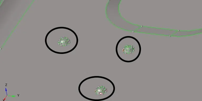

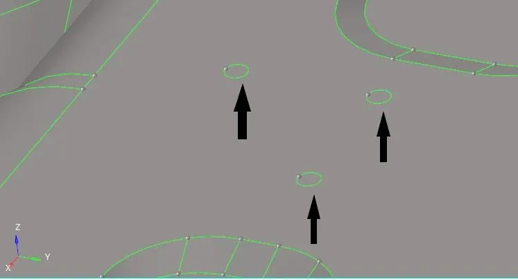
- Filling up the missing surface is also one of the import parameter, we basically use "ruled" or "spline/filler" command to fill the surface. To use ruled command, go to "geometry" then select "surfaces", after that click the option "ruled". Select the two lines in between which the surface is missing and then click "create", surface will get created.
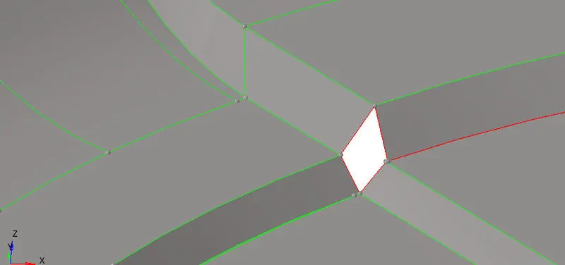

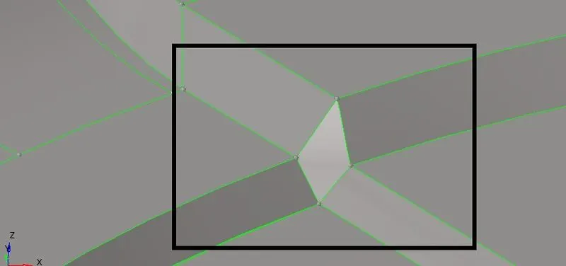
- "Toggle edge" and "replace point" option are very helpful to join a surface with less gap in between themself. This two command are present under "quick edit" pannel in geometry.
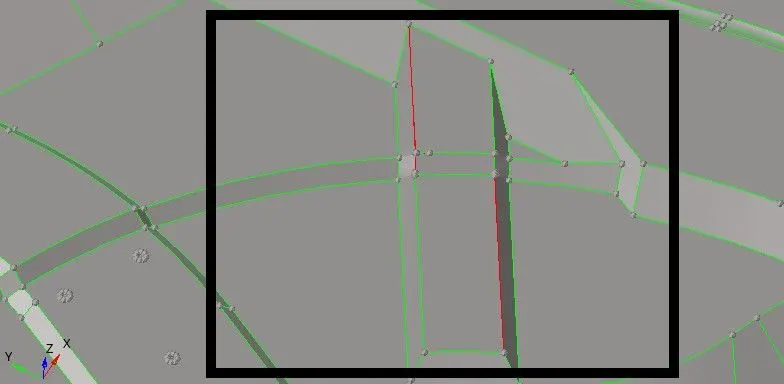
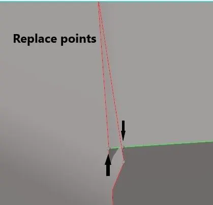
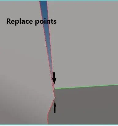
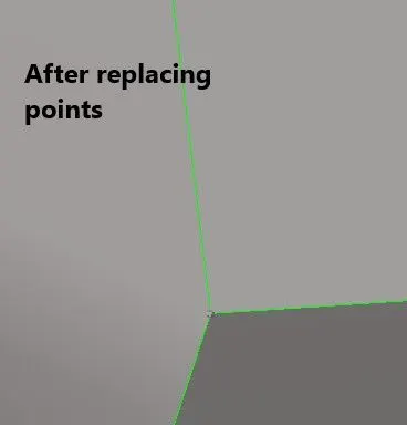
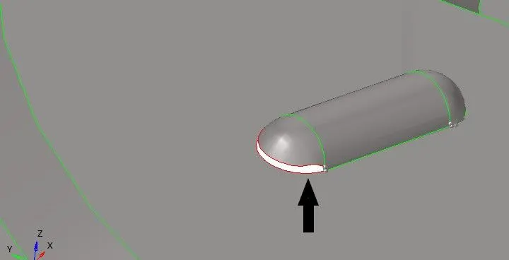
- We can also use replace edge option to fill the gap between the two edge. For that, go to "geometry" then select "edge edit" under edge edit select "replace". Select the two line from the display pannel and then click "replace".

5.Setting Quality Parameter.
| S.N | Quality Criteria | Value |
| 1 | Aspect Ratio | 5 |
| 2 | Skewness | 45 |
| 3 | Warping | 15 |
| 4 | Taper | 0.5 |
| 5 | Min. Length | 2 Units |
| 6 | Max. Length | 8 Units |
| 7 | Min angle Quad | 45 |
| 8 | Max angle Quad | 135 |
| 9 | Min angle Tria | 20 |
| 10 | Max angle Tria | 120 |
| 10 | Tria % | 10 |
- Target element size should be "5". For setting quality parameter, go to "preference" then select "parameter file setting" enter the value as per given table and then click apply.
6.Meshing.
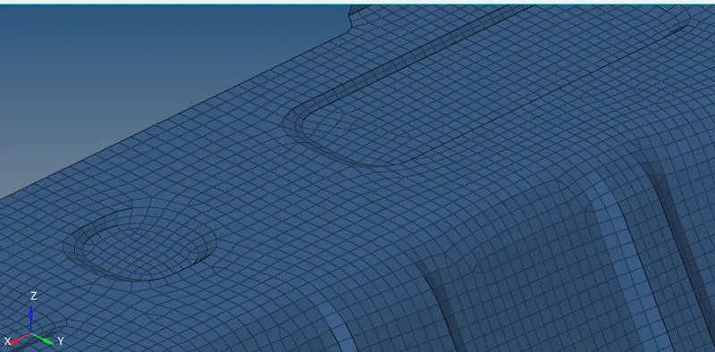
- We will go for "2D" meshing on our component and then assign the thickness to it. For "2D" meshing, go to "2D" then select "automesh" after that enter the target element size as "5" and type as "mixed". Split the given component into different part and then perform meshing accordingly for getting a better mesh flow.
- There are many different ways in which we can manage our mesh flow, connectivity and trias properly. One of the easiest way to do so is by using "quality index" which is present in the main menue bar under "2D".


7.Assigning Thickness.
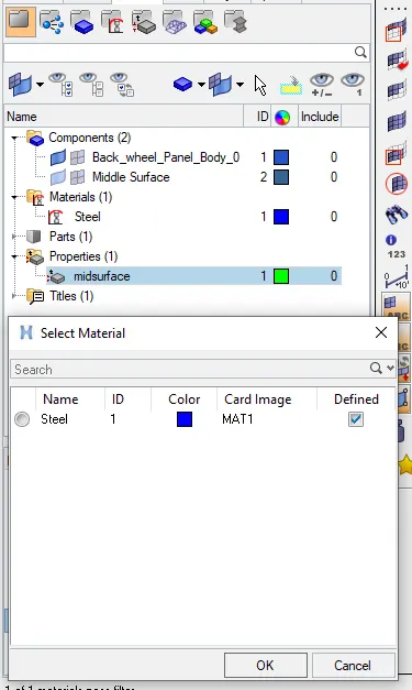
- For assigning thickness to our component we have to first create a property and material. Then we have to enter the thickness value in our property and then assign that property to our component.
- We have to first measure the thickness of our sheet metal component, this can be done with the help of "distance" option under "geometry". Under distance option select the two points and note the value.
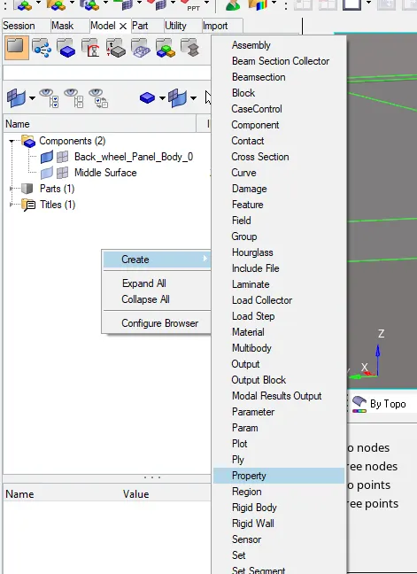
- After that go to the Tab bar and just right click on it, select the option "create" and the click "property". Under property enter the thickness value as "0.75" which we have measured, similarly create a material by just right clicking on Tab bar.
- Assign the property and material to our component, then under tool bar switch the option from "2D traditional element representation" to "2D detailed element representation", to see the thickness.
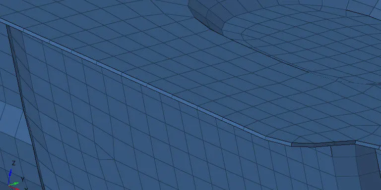
RESULT.