Week 4-1D Element Creation Challenge
OBJECTIVE-
- Generating mesh and developing the 1d element on it.
- Defining the cross-section to the 1d element & assigning the property to them.
CAD model Image-
Procedure-
1.Importing the file.-
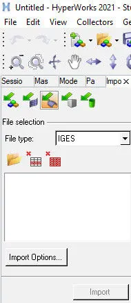
Open HyperWorks then from the tool bar select "Import geometry", select the file type as a 'IGES' file. After selecting the file click import.
2.Midsurface.-
- Midsurface is the surface between the two surfaces. If for our 3D component we do the meshing directly then the number of nodes and elements will be very high which means storage requirement will be high & also the processing power will be high. In such cases we do the midsurfacing which basically create a shell element (2d representation of a 3d object).
- For creating a midsurface go to the geometry and select "midsurface" from the main menue bar.
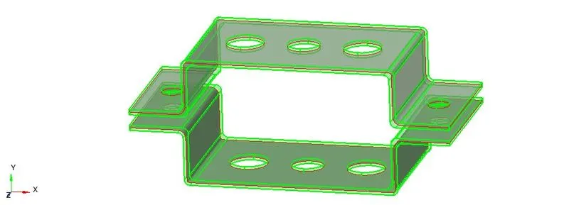
- After that give the command as "auto midsurface" and then in the "extraction options" select as "skin offset". Select the surface (it is reliable to create midsurface of the two brackets separately).
- After selecting the surface give the command as 'extract'. Midsurface will be created.
 Extraction option as "skin offset".
3.Meshing.-
- Before meshing delete the solid by selecting "delete" from the tool bar and then select "displaced" the entire solid will get selected and then give the command as 'delete entity'. After that go to the tab bar and delete the two parallel bracket component.
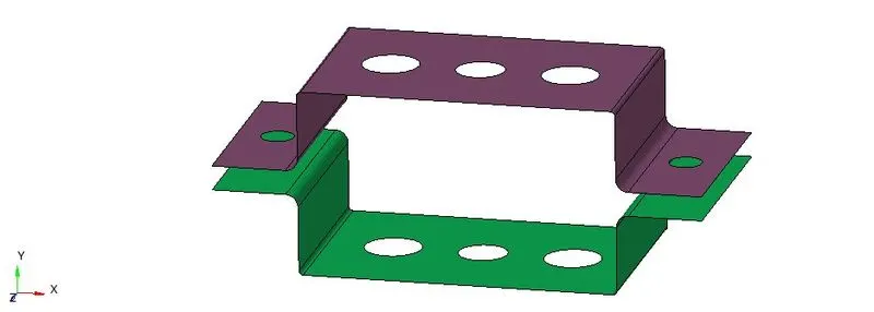 Midsurfaces of two bracket.
- Before meshing create a washer split, for that go to the geometry and select "quick edit" from the main menue bar. After selecting quick edit go to the "washer split" and give the offset value as "5". From the graphical area select the circles and click the circle so that washer split get created (it is provided from generating a better mesh).
- For meshing go to the 2d option and then select "automesh" from the main menue bar. After that give the element size as "5 unit" & mesh type as "mixed". Give the command as surface and select "displayed" the entire surface will get selected. Select mesh, the entire component will get mesh.
- Hide the element from the surface by selecting the hide command from the "tab bar".
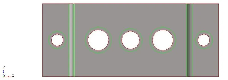 Washer split of offset "5".
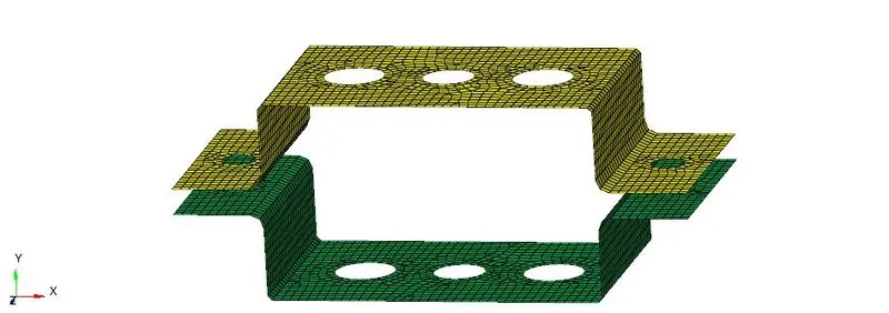 Meshing.
4.Creating material.-
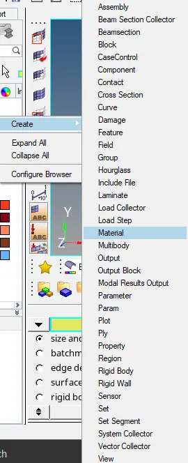
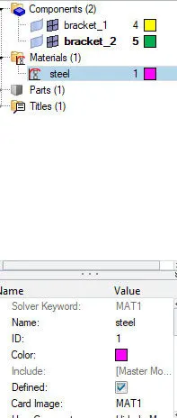
- For creating a material go to the tab bar right click the mouse, go to create and select the option as material. After selecting the material give the name as 'steel', check all the specification of steel from the tab bar, give the card image as "MAT1" (card image depends upon the solver specific).
5.Creating RBE2 link.
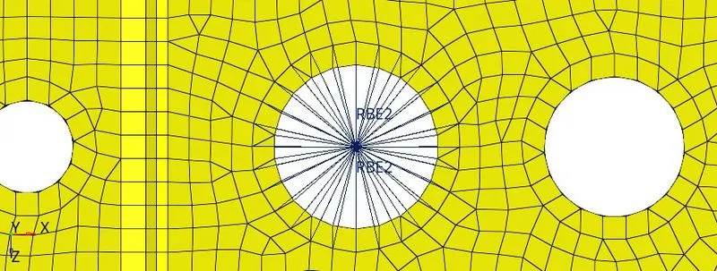
- For creating RBE2 link go to 1d and then select "rigids". After selecting rigids go to 'create' and select the degrees of freedom which is to be constrained along x, y & z co-ordinate system.
- Select "calculate node" and then select 'nodes by path', go to the graphical area select the nodes from the periphery of circular hole then assign the degrees of freedom as per requirement. Select element type as "RBE2" and then click create, RBE2 link will get created.
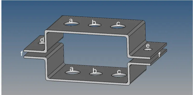
- RBE2 link is to be created for (a, d & e).
- For "a" translational DOF should be Constrained with RBE2 link, for that select degrees of freedom as, "dof1", "dof2" & "dof3" from the main menue bar.
- For "d" & "e" translational and rotational both degrees of freedom should be constrained with RBE2 link, for that select degrees of freedom as, "dof1", "dof2", "dof3", "dof4", "dof5", "dof6".
 For "a".
 For "d" & "e".
6.Creation of RBE3 link.-
- For creation of a RBE3 link go to 1d and the select "rbe3". After selecting RBE3 go to 'create' and select the degrees of freedom which is to be constrained along x, y & z co-ordinate system.
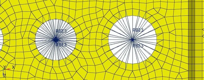
- Select "calculate node" and then select 'nodes by path', go to the graphical area select the nodes from the periphery of circular hole then assign the degrees of freedom as per requirement. Select element type as "RBE3" and then click create, RBE3 link will get created.
- RBE3 link is to be created for (b & c).
- For "b" all degrees of freedom is to be constrained means both translation and rotation. For that select the degrees of freedom as "dof1', "dof2", "dof3", "dof4", "dof5", "dof6".
- For "c" x & y degrees of freedom is to be constrained. For that select the degrees of freedom as "dof1", "dof2", "dof4", "dof5".
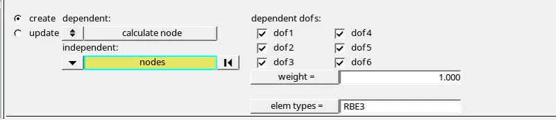 For "b"
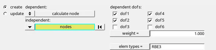 For "c".
7.Creating bracket property.
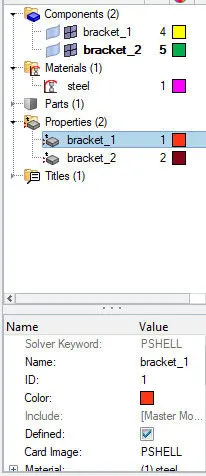
- For creating bracket property go to the tab bar right click the mouse, go to create and select as property. Create two seperate property as "bracket_1" and "bracket_2".
- Under property select the card image as "PSHELL", thickness as (T=2) and material as steel.
- Under component select the bracket_1 and bracket_2 simultaneously and assign the property which we have create for them.
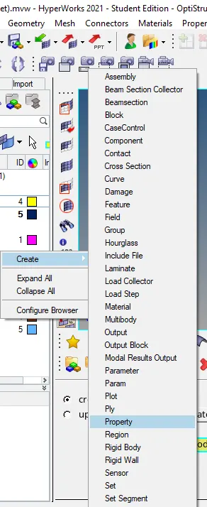
8.Creating geometry.
- For creating geometry go to 1d and select "Hyperbeam". After selecting Hyperbeam select as standard section.
- After selecting standard section under standard section library select "Hyperbeam" and then under standard section type select "thinwalled box". A hyperbeam view will get generated.
- Box is to be created for "a", under parameter defination give the dimension value as, Dimension a=12, Dimension b=10 and Thickness t=0.75.
- For creating "I" section for "b" under entities just right click the mouse then go to create and under create go to standard section then select hypermesh and under hypermesh select "standard I section". Give the dimension as, Dimension a=8, Dimension b=10, Dimension c=8.5, Thickness t1=0.75, Thickness t2=0.6, Thickness t3=0.6.
- For creating "X" section for "c" under entities just right click the mouse then go to create and under create go to standard section then select Optistruct and under Optistruct select "CROSS". Give the dimension as, Dimension DIM1=5, Thickness DIM2=1.2, Dimension DIM3=10, Thickness DIM4=1.2.
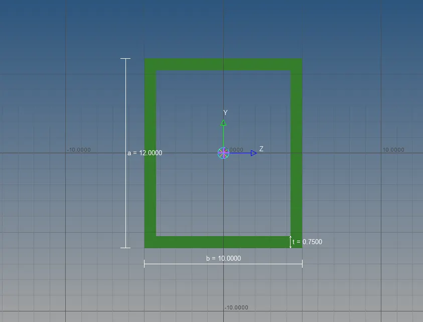 1. Box.
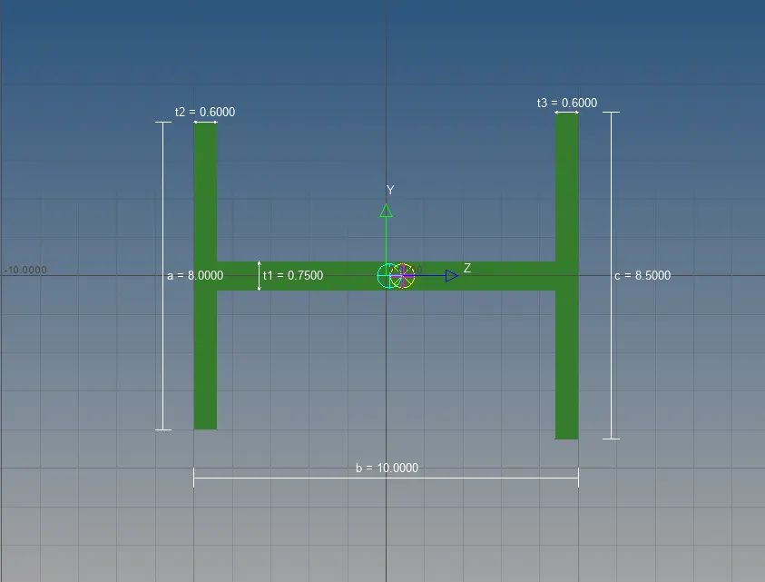 2. I
2. I
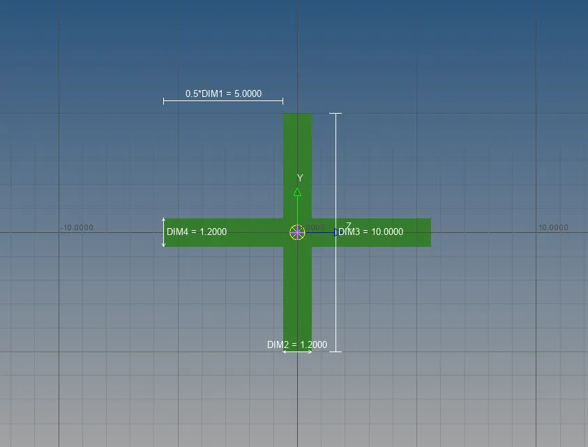 3. X.
3. X.
9.Creating properties for (Rod, Beam & Bar).
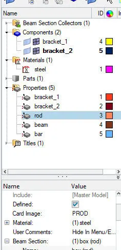
- For creating property for Rod, Beam and Bar go to the tab bar right click the mouse, under create select property. Create three different property and rename it as Rod, Beam and Bar respectively.
- Under Rod select the card image as "PROD", then under material select "steel" and under beam cross section select "BOX". The box dimension which we have created will get alloted to the rod property.
- Under Beam select the card image as "PBEAM" then under material select "steel" and under beam cross section select "I". The I section dimension which we have created will get alloted to the beam property.
- Under Bar select the card image as "PBAR" then under material select "steel" and under beam cross section select "X". The X section dimension which we have created will get alloted to the bar property.
10. Creating Rod.
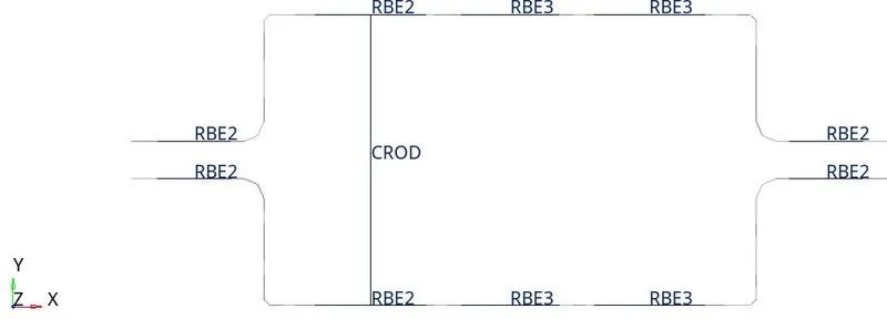
- For creating rod go to 1d select "rods" from main menue bar. After selecting rods select the two nodes from RBE2 link from "a", nodes which is selected should be opposite to each other.
- After selecting nodes give the property as "Rod" and element type as "CROD", rod will get created and will be displayed in the graphical area.
11. Creating Beam.
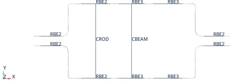
- For creating beam go to 1d select "bars" from the main menue bar. After selecting bars select the two nodes from RBE3 link from "b", nodes should be opposite to each other.
- After selecting nodes give the property as "Beam" and element type as "CBEAM", give the orientation as y-axis, beam will get created & will be displayed in the graphical area.
12. Creating Bar.
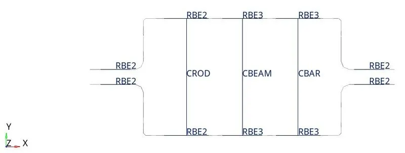
- For creating bar go to 1d select "bars" from the main menue bar. After selecting bars select the two nodes from RBE3 link from "c", nodes should be opposite to each other.
- After selecting nodes give the property as "Bar" and element type as "CBAR", give the orientation as y-axis, bar will get created & will be displayed in the graphical area.
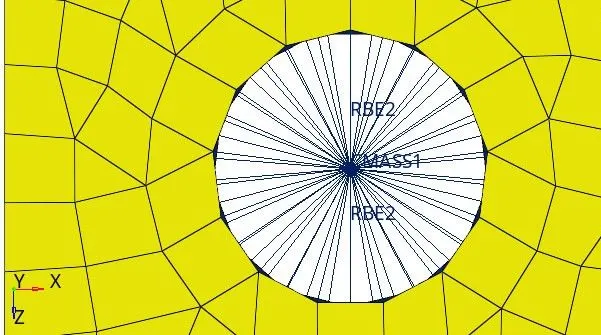
13. Applying Mass of (10).
- Mass of "10" is to be applied at RBE2 links at "d" & "e".
- For applying mass go to 1d and select "masses" from the main menue bar. After select masses select the node from RBE2 link from "d" & "e". Give the mass as "10" and property as bracket_1 and then click create, masses of 10 will get apply at "d" and "e".
14. Creation of spring element.
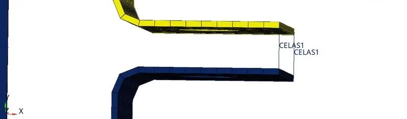
- For creation of a spring element go to 1d then select "springs". After selecting springs select the two node in between which we want to create our spring element, give the degrees of freedom as "dof1". Spring element will get created.
- Spring element we are using for joining the two components. Spring element is placed at the location "f".
RESULT.
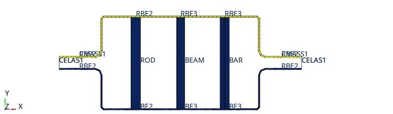
1. 1d Traditional element representation.
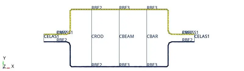
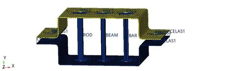
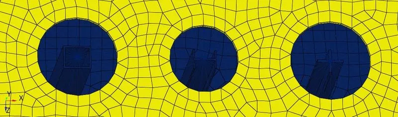
2. 1d detailed element representation.