Week 6-Meshing of Hood Challenge
OBJECTIVE
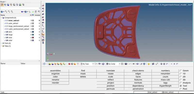
Generating mid surface and meshing the whole component with mixed quads by following the quality criteria.
CAD MODEL IMAGE
PROCEDURE
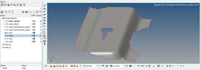
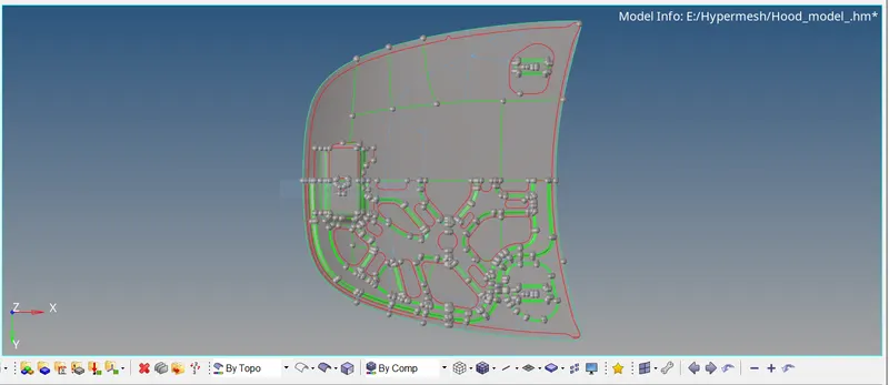
For this model we have to clean the model that has only green lines and red lines because we don’t have any 3 sharing edges. now we will isolate every part for creating a mid surfaces.
Creating midsurface
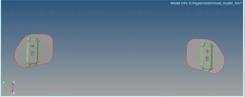
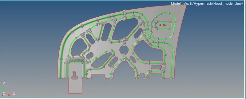
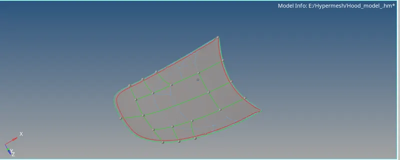
Go to geometry Select the component with you want to create, or isolate only the part which you want to select, so we can select the component with as displayed. Now we will able to create a mid surface for every part. And give a new name to that component. For getting a good mesh flow the distance of construction line should be between the max and min quality. So, we will reconstruct the construction line according to the feature shapes. In the hemming region consider only the top middle line by toggling the nearest lines. In the flat surfaces we don’t need the straight lines. In the outer extract part, we can assume the straight lines only. Now we have a clear geometry. Go to 2D auto mesh, mesh every single surface one by one. So, we can concentrate the trias and by also capturing the surfaces without fail. For the outer surface I reconstruct the geometry lines like this, so we can achieve good mesh flow. For the inner surface I will show the geometry Since it is a symmetry part, so I cut the part into half and mesh them one by one. I meshed the half part and reflect it to the final. So it is much time saving tip. Where ever the trias on the flat surface can be pulled out in the quality index. Thus opposite facing trias can be remeshed or pulled them towards each other. Trias on the free edges can be eliminated by pulling them outwards. Trias on the feature can be cleared using element optimization and place node. U can reflect the mesh to the outer by using command, tool Before reflecting the mesh make sure you’ve cleared all the mesh distortions. RESULTS By using these tips we can achieve the better mesh for this component by adjusting the construction lines. FINAL IMAGE