Week 6 - Creating connection for Rear door
CREATING CONNECTION FOR REAR DOOR
WEEK- 6
AIM:
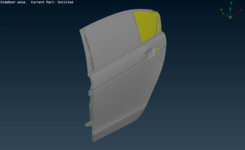
Connections for the Rear door by using different 1D elements.Create and Apply different PIDs for different components.
GIVEN:
METHODOLOGY:
Performing suitable connections with different methods are used below
PROCEDURE:
IMPORTING FILE:
- Import the give model Files ->open->SideDoor.Ansa
- For 1D connection, there are different types of methods to connect the elements.
- For bolt connection we can use RBE2 element
- Go to Modules->NASTRAN->ELEMENTs->RBE2 select many nodes option and pick the node to connect, Master node are assigned automatically
CM is DOF-> 123456, where all movement are arrested.
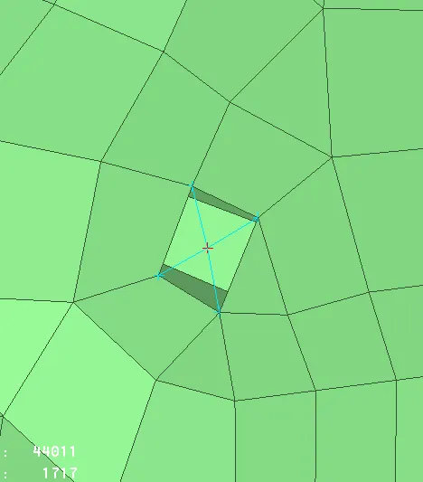
- RB2 cluster are used in two different element connections, simply by selecting two different element in RB2 options
- Master node are assigned automatically
- CM is DOF-> 123456, where all movement are arrested.
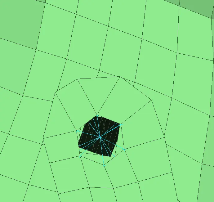
- similarly these methods are used in various areas where RBE2 connections are needed.
- connections Below are used for Hinge in Door which allows Z-axis rotation
- For that we have to connect two Cluster RBE2 areas,to Connect Two Master node We can use Two node connection in RBE2 Elements
- CM is DOF-> 12345, Here only 3 translation and 2 rotation movement are used. Z-axis Rotation are allowed for Door to open and close.
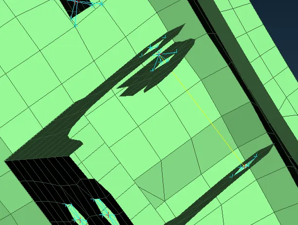
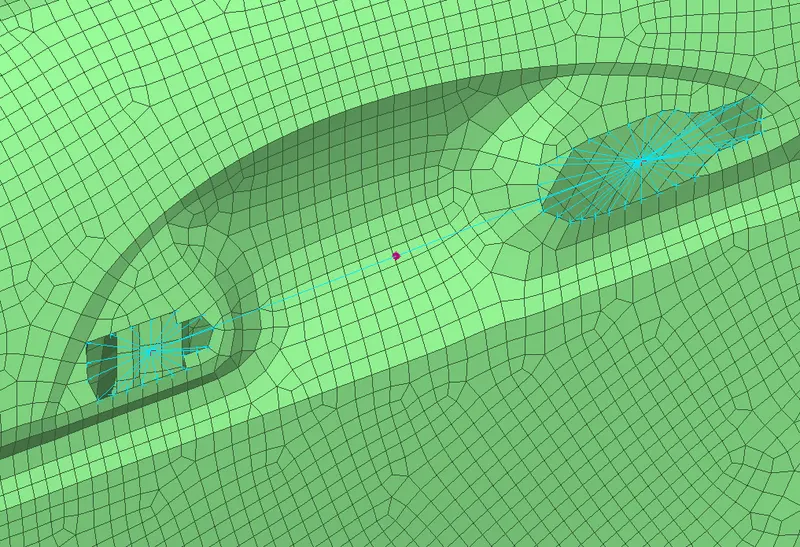
- Two holes should be individually assigned RBE2 many nodes,by selecting Modules->NASTRAN->ELEMENTs->RBE2->MANY NODES select the node of the holes which will be slave Nodes and master node will be assigned automatically.CM is DOF-> 123456.
- After assigning the RBE2 to the holes, join the master node of both the holes by RBE2 many nodes to represent the Door Handle.
- The Door handle Should be assign a mass by Modules->NASTRAN->ELEMENTs->CONMi->CONM2->NODES select the node to assign the mass and provide the mass value in Tonnes.
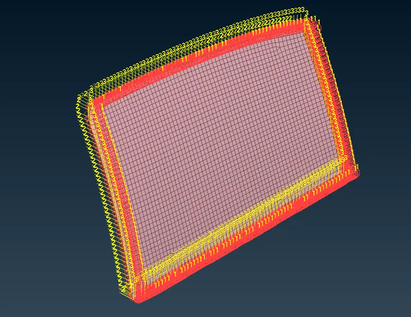
- The connection between the window glass with the door are done by RBE3-CBUSH-RBE3.
- To apply these first we have to create a curve on the outer line on the mirror by Modules->MESH->PERIMETERs->FEAT2CURVE
- Convert the curve to spotline individually by assembly->convert-> curve, select the curve to convert.
- To assign and realise the curve to RBE3-CBUSH-RBE3, Go to assembly->connection manager-> Select one curve. First assign the P1,P2 one by one right click on P1 and select the part and right click on P2 & select the another part.Enter 10 in S Which indicate the space between the CBUSH. Then go to FE represent Setting select Fe Rep type RBE3-CBUSH-RBE3, Search distance as 50 and click on keep all branches in interface. PBUSH ID in body has to be created new, eneter K1to K6 in that, apply and realise it.CBUSH will assigned to the curve.Similarly asssign the CBUSH to other curves of Glass window.
- As the CBUSH having their own local coordinates and oriented According to their attachment with P1 and P2.Local coordinate should be oriented in one direction with respect to Global coordinates.In Database, Select Elements->CBUSH, change the orient and enter the value of CID as 0 for all the CBUSH.
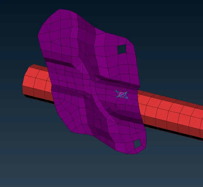
- Spotweld connect by RBE3-HEXA-RBE3
- Before applying spotweld connection First create a 3D point by modules->Topo->points->ONCOG and select the edge of the elements.
- After creating 3D point, convert the 3D point to Spotweld point in Convert option visible in assembly.
- To assign and realise the curve to RBE3-HEXA-RBE3, Go to assembly->connection manager-> Select the point.First assign the P1,P2 one by one right click on P1 and select the part and right click on P2 & select the another part.Then go to FE represent Setting select Fe Rep type RBE3-HEXA-RBE3,Search distance as 20.Apply and realise it.similarly these methods are used in respected areas.
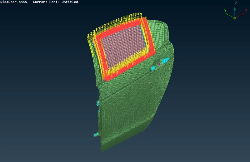
FINAL OUTPUT:
LEARNING OUTCOME:
- Get a knowledge in 1D connection of elements with different methods.
- Different type of Connections like spotweld,RBE2,RBE3,Seamweld are understand.
- Will able to perform connection in any model.
CONCLUSION:
The 1D element connections are done properly with respect to connection types.