Connecting the Rear door assembly of an automobile for NVH analysis
CONNECTING THE REAR DOOR ASSEMBLY OF AN AUTOMOBILE FOR NVH ANALYSIS
AIM:
The objective aims to connect the Rear door assembly components by deploying different types of connections at various locations to carry out a NVH analysis on the Rear Door.
PROCEDURE:
1. Import the given model in to ANSA. Since the given model is in NASTRAN format the input option is used.
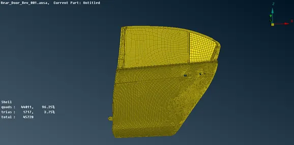
Fig: Input Model.
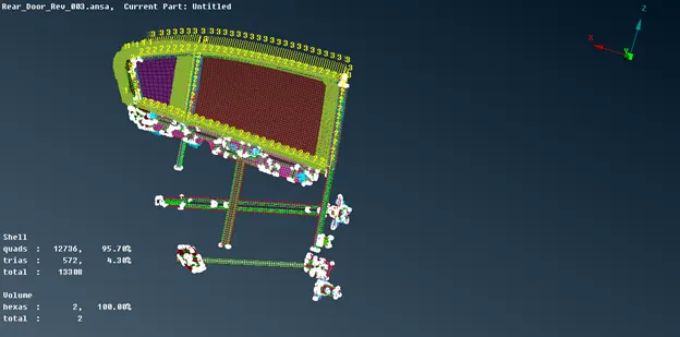
2. Segregate the components by assigning PID to each and individual parts as shown in figure.
3. Check the model properly and ensure that the parts are separated properly.
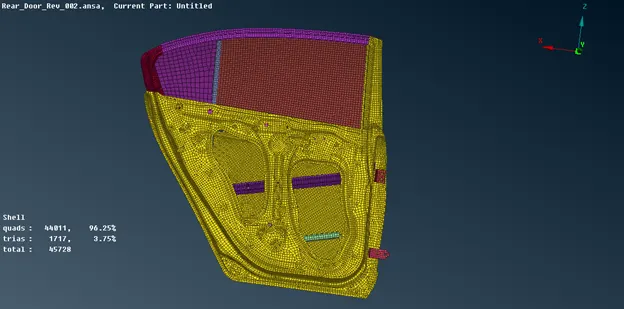
Fig: Segregated model.
4. All the connections were deployed in Nastran deck module and start connections part by part by isolating the required locations.
5. Connect the Hinges with bolt Connections to the Door Body since the hinge is rigidly connected to the door and model has holes to clamp the same as shown in figure.
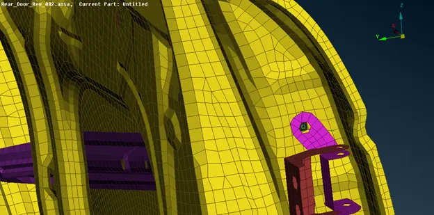
Fig: Door Hinge.
6. To deploy a bolt connection, create a 3D point at the center of the hole and convert that point in to a Bolt.
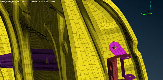
Fig: Bolt Location.
7. Open the connection manager and select the bolt icon, select type as bolt, set the search distance as 10 and select the P1, P2 and P3 and apply then realize the connection.
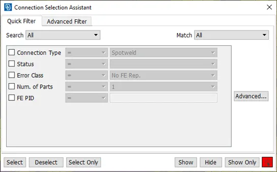
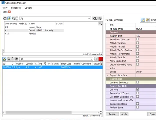
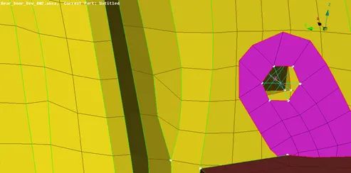
Fig: Bolt connection.
8. Similarly repeat the same procedure for bottom hinge as shown.
9. The hinges were connected each other with RBE2 elements. The holes were connected with multi nods cluster RBE2 (multi node) elements and the Hinge pin is represented as 2 nodes RBE 2 elements which connects master nodes of cluster RBE 2 elements as shown.
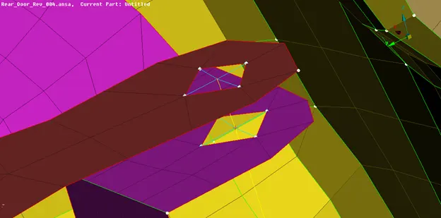
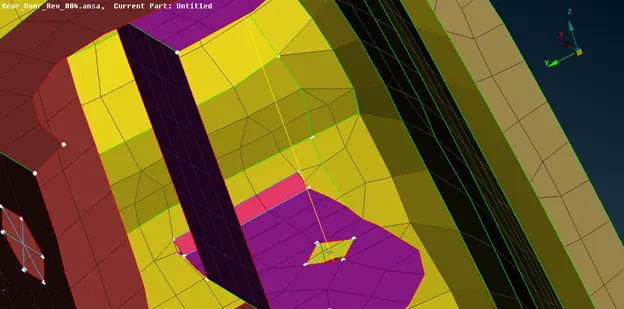
Fig: Hinge connection.
10. The hinge must rotate in the axis in which the door moves. The DOF must be released in that particular direction. According to the global co-ordinate of model the door should rotate along axis Z hence the DOF of Rotating Z must be released as shown in figure.
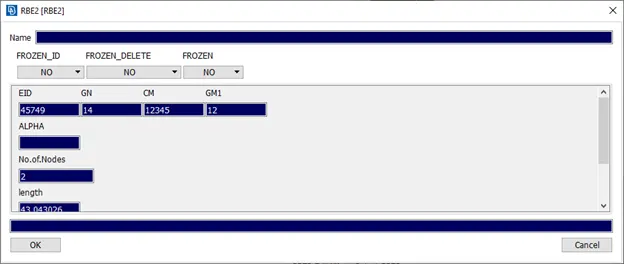
Fig: Releasing DOF.
11. Repeat the same procedure for the bottom hinges.
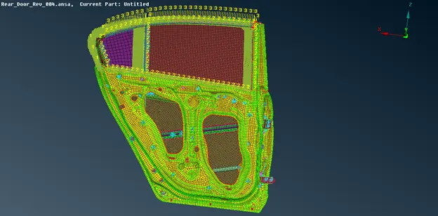
12. The other side of the hinge plate must be welded to the door as shown in figure.
13. Extend the hinge edge near to the door surface and create a curve using the hinge edge.
14. Convert the line in to seam line and open the connection manager and select the same line.
15. Select weld type as Y-Joint Shell and set the search distance, width and height and P1, P2 and the base sheet.
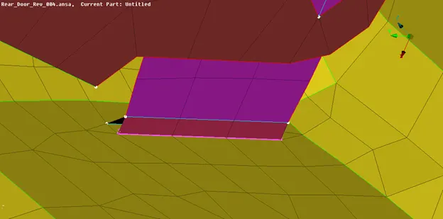
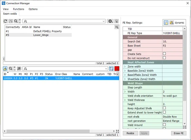
Fig: Seam weld.
16. Apply and realize the connection and repeat the same procedure for the other hinge.
17. The door handle is represented wit cluster RBE2 elements as shown in figure and Mass of 100gms is added to the master node of the link using Conmi option.
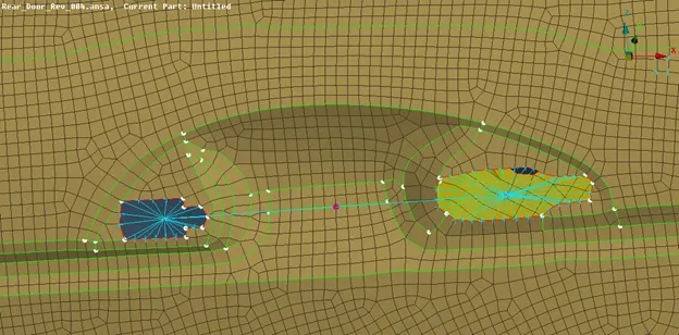
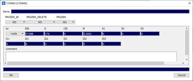
Fig: Handle Door connection.
18. Most of the inner parts were connected with spot welds. To deploy a spot weld convert a 3D point in to a spotweld point and through connection manager set type as RBE3 – HEXA – RBE3 and set Pin Flags as 123456. Set D as 5 and select P1 and P2 and create a solid PID for the spot weld and realize the connection.
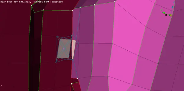
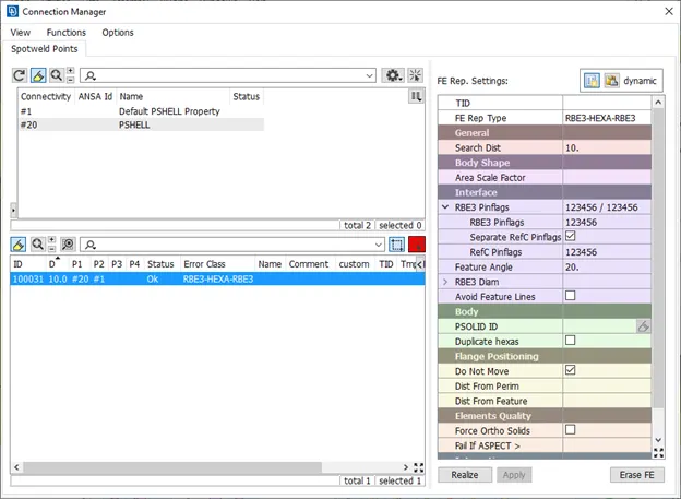
Fig: Spot weld.
19. Repeat the same procedure in the required location.
20. The glass must be connected to the door with the help of weather strips which is represented as bush elements in NVH. To deploy the connection create curves using glass perimeter and convert it in to seam line.
21. Since the glass is sliding the bottom side of the glass must be connected to the either side of the door, hence a curve must be offset to a distance of 1 units and using that curve connections were created and rest 3 sides were connected to the guides from one side only.
22. For the glass connection select the type of connection as RBE3 – CBUSH – RBE3, set search distance as 50 and select check the keep all branches option and select the parts as P1 and P2 and Realize.
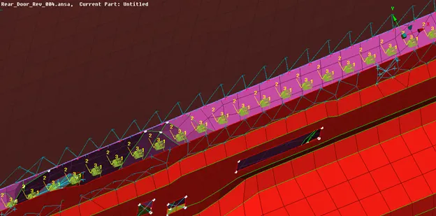
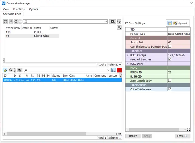
Fig: CBUSH connection.
23. Repeat the same step for the fixed glass but it has to be connected from either side of the door.
24. The orientation of coordinates of the CBUSH element must be same as that of global coordinate’s orientation. In order to do that go to elements from data base – CBUSH– select all the elements and modify - set rule to orient with coordinates – and CID as 0.
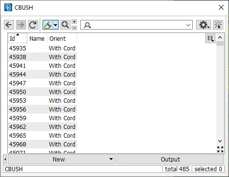
Fig: Orientation of CBUSH elements.
25. Connect the parts with cluster RBE2 elements in necessary locations.
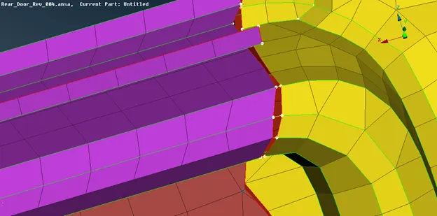
Fig: 2 Noded RBE2 elements.
26. The Reinforcement bar bracket must be connected using seam weld. Repeat the above said step for welding; in the weld type select overlap shell for seam weld.
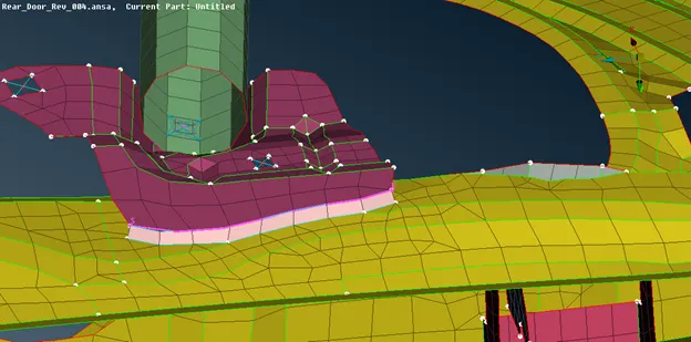
Fig: Seam Weld.
27. Some of the elements were disconnected due to the CAD errors that must be connected with 2 noded RBE2 elements.
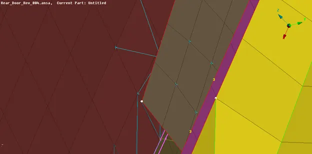
Fig: Cluster RBE2 connection.
28. The guide was extended to connect the sliding glass with cluster RBE2 elements.
29. The fixation holes were represented with the help of cluster RBE2 elements as shown.
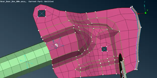
Fig: Fixation Holes representation.
LEARNING OUTCOMES:
1. Deploying connections at various locations.
2. Selection of connections and their applications in various locations.
3. Different types of element representations in NVH.
4. Types of seam welds and their specifications for NVH.
5. Manual and automatic bolt connections.
6. Differences in cluster and 2 noded RBE2 elements.
7. Representation of weather strips in NVH.
RESULT:
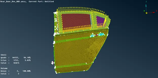
The Given Rear door model is connected using different connections such that all the components are connected to the neighboring parts in order to perform NVH analysis.
FINAL MODEL