Week 6 - Creating connection for Rear door
AIM: To implement connections for a Rear Door mesh model.
Objective:
- Understand different types of connections and 1D elements.
- Perform connections as needed.
Description:
Steps involved in these connections:
- Import the given Rear door FE model.
- Study and understand the geometry and its mechanism.
- Establish connection between all the bolt holes
- Provide connections where ever the welding is needed.
- Provide connections at the window perimeter.
There are five types of connections that are mostly used in ANSA:
- Spot
- Adhesive
- Seam
- Hemming
- Bolt
1D element : In this case, the bolt connection created is a 1D element instead of actual bolt which reduces the run time during the analysis.
RBE2 [MANY NODES] : Defines a rigid body element of form 2 (RBE2) between selected grid points, 3D-points etc. This element is a rigid body with independent degrees of freedom specified at a single grid point and with dependent degrees of freedom at an arbitrary number of grid points.
RBE2 [TWO NODES] :Defines a rigid body element of form 2 (RBE2) between two selected grid points, 3D-points etc. This element is a rigid body with independent degrees of freedom specified at one grid point, and with dependent degrees of freedom at the other grid point.
RBE2: Rigid link to transfer motion from the independent nodes to the dependent node. RBE2 doesnt have a Property ID. The Master is in center for the RBE2.
RBE3: Rigid link to distribute loads and will not induce any stiffness. It is viceversa of RBE2.
Let us start looking at the Rear door model and identify the different connections.
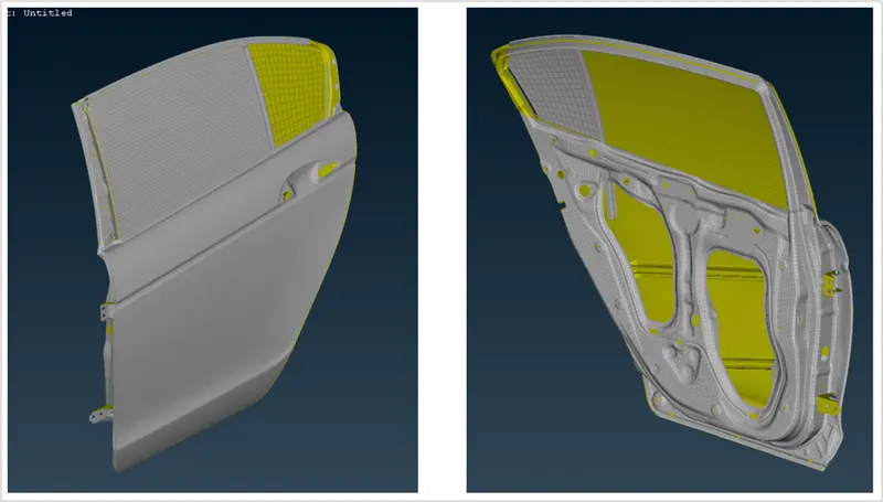
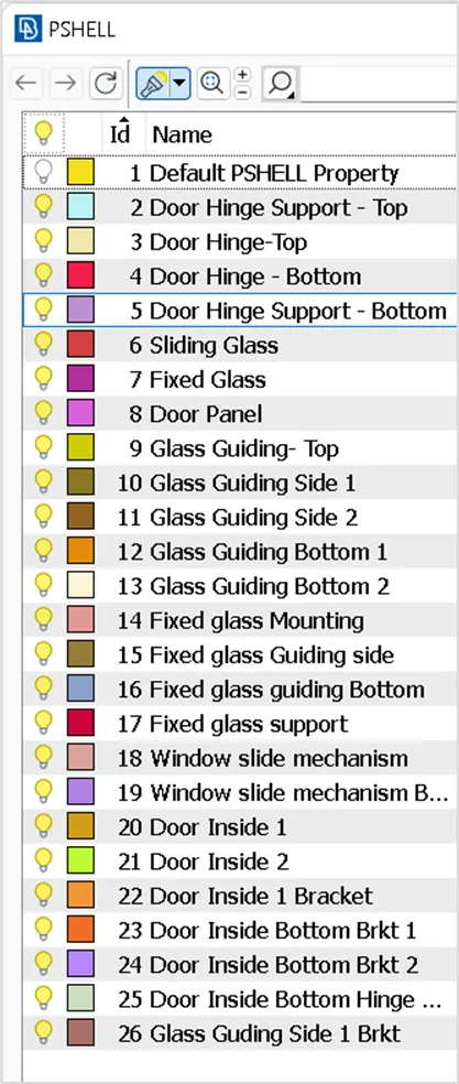
Create PID:
First step is to create different PIDs for the given model.
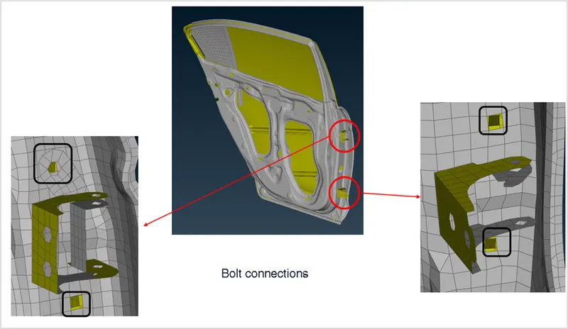
Bolt Connections:
The below picture shows a connection between the Hinge support and the door body. This connection must be established by a bolted one.
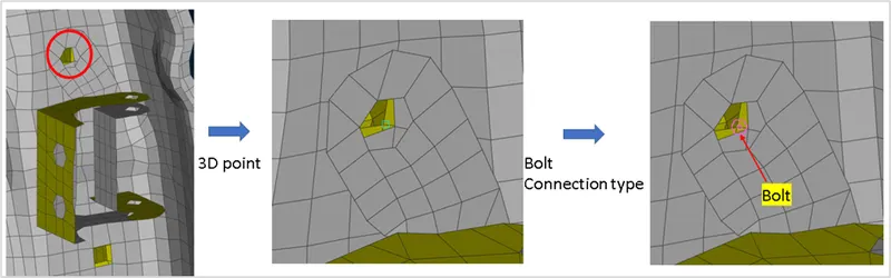
To create a bolted connection, firstly a 3D point must be created on any of the holes. It can be done by selecting the nodes of the hole: Topo > Points > On COG .
Once the 3D point is created it should be converted to bolt type using the option:
Convert > 3D points > Connection type > Bolt
Once the bolt is connection type is established, the next step is to connect the parts with bolted connection using RBE2 element. It can be done as follows:
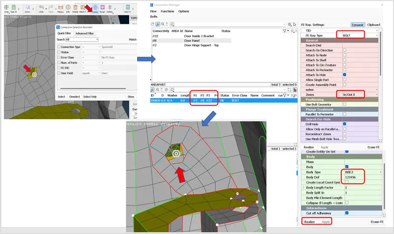
From the above picture it can be seen that three parts(P1, P2,P3) are selected for the boltedconnection. The highlighted options in the FE representation settings are applied and the connection can be realized by using "Realize" option at the bottom. Based on the functionality between the parts the degrees of freedom must be selected. In this case, it is constrained in all the directions.
Similarly, it is done in both top and bottom hinge supports and the connections are as shown below.
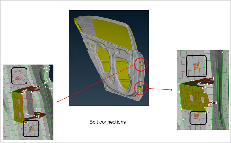
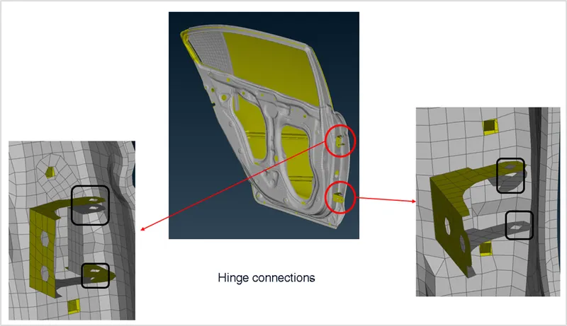
Hinge Connections:
In the hinge supports area, there must a hinge connection established for the movement of the door in one direction. The connections areas are highlighted as follows:
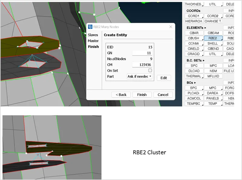
Inorder to establish this connection firstly we establish the RBE2 cluster as shown between the parts using "RBE2 Many nodes".The path is NASTRAN>ELEMENTs>RBE2
Once the RBE2 cluster is created for the top and bottom interfaces, hinge connection can be provided by using "RBE2 Two nodes" as shown. Since the door must move in one direction only, the degrees of freedom must be given in such a way that rotational freedom must be free in Z axis.
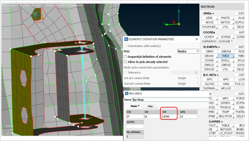
Similarly, the hinge connection is provided at the bottom support as well as shown below:
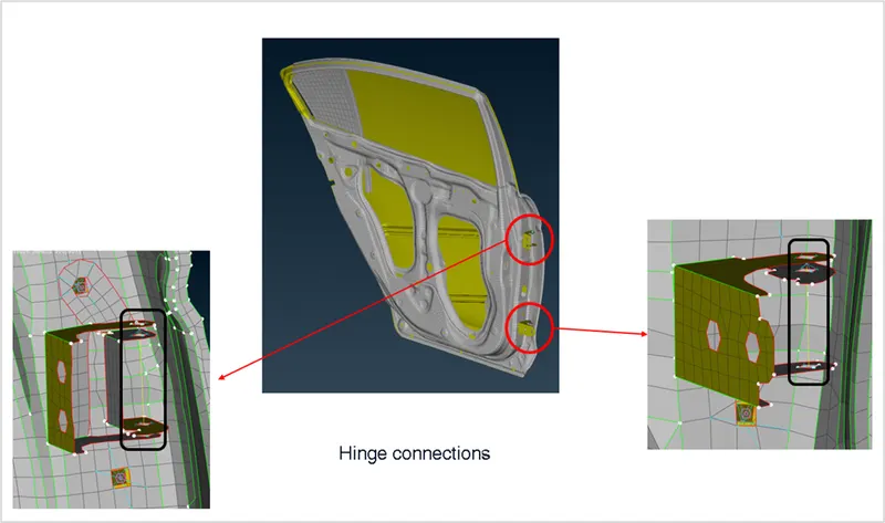
RBE2 Connections:
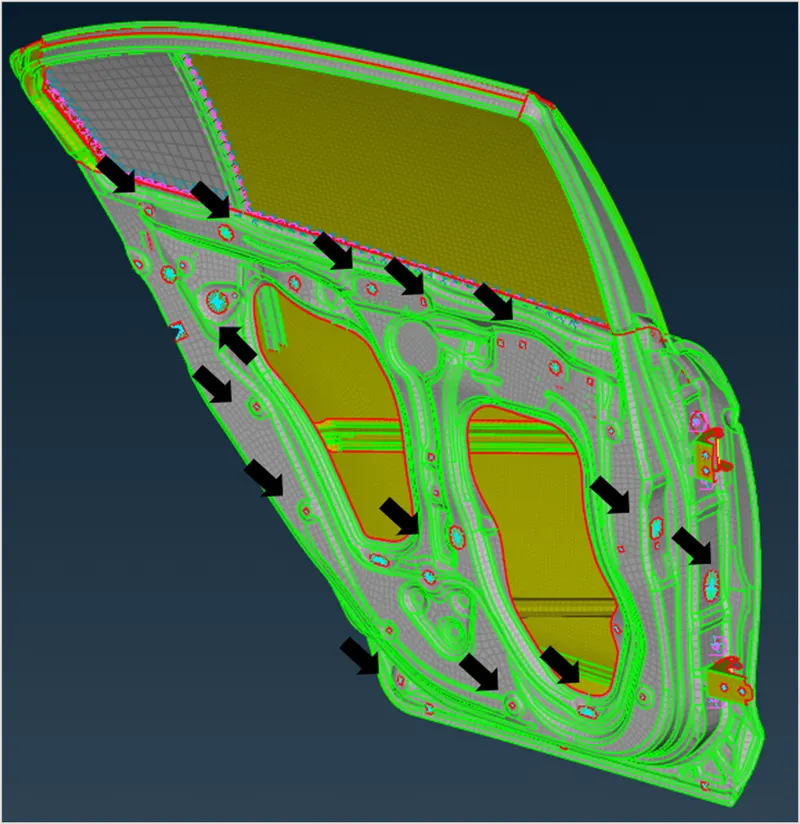
Rigid connections to be provided using RBE2 element at the rest of the connections as shown. At some of the places, although there are no interface part in this assembly, but there will be interfaces in next level assembly. We need to establish the connection in this level itself so that it can be utilized in next levels.
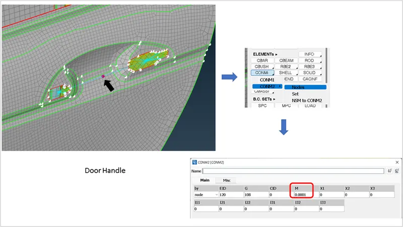
At the door handle interface, RBE2 cluster is provided and a common connection is established as shown to provide a door handle mass at its COG. Please note the mass considered in this section is in tonne.
Spot weld connection:
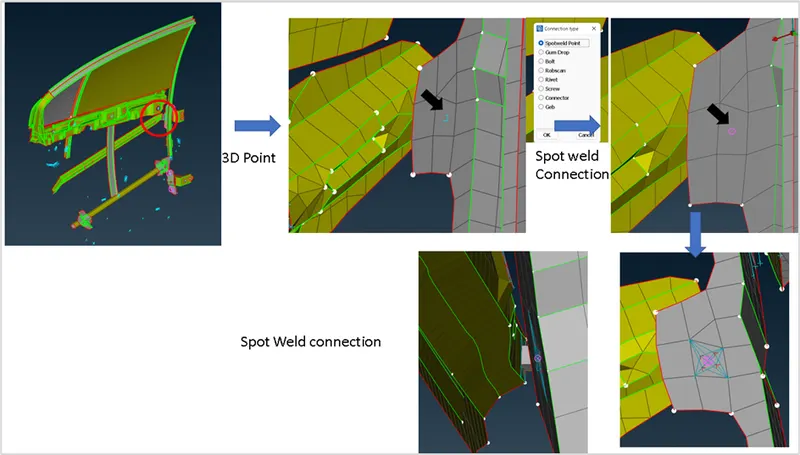
At the connections that are overlapping and no holes, weld connection type must be provided. In the following connection, spot weld is provided as shown.
Create 3D point : Topo > Points > On COG .
Convert > 3D points > Connection type > Spot weld
For NVH in Nastran, Spot weld the representation would be RBE3-HEXA-RBE3
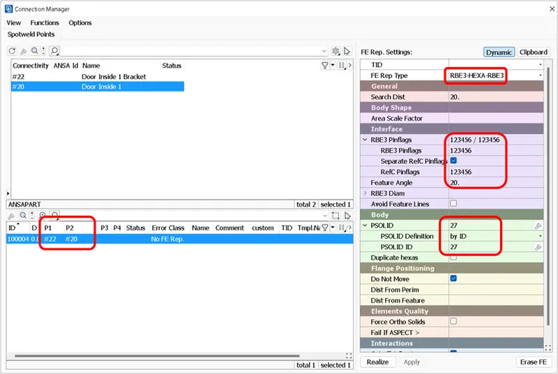
In the connection manager, the required two parts must be selected and FE representation type "RBE3-HEXA-RBE3" must be selected and all degrees of freedom must be constarined.
For the spot welds, there must be a Psolid created and assigned as shown.
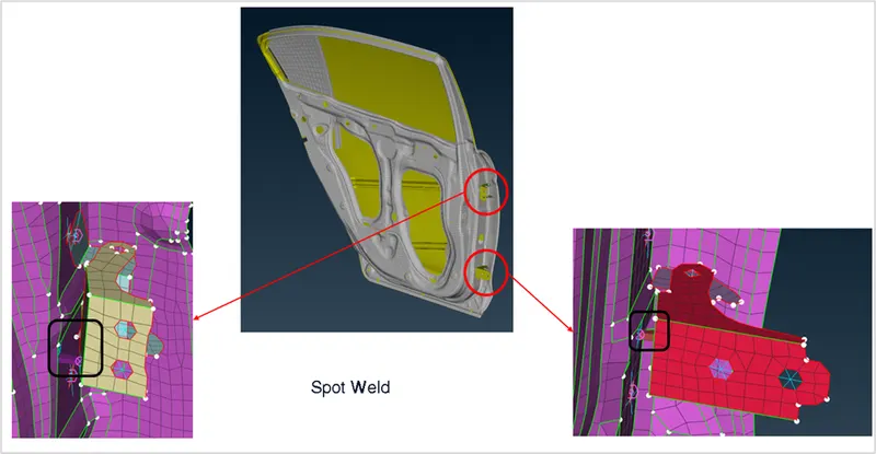
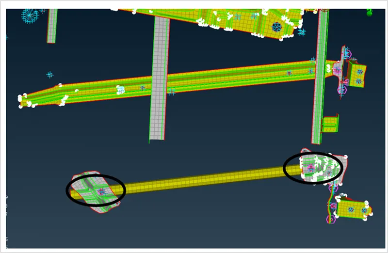
Simialrly, the spot weld connection is provided at the remaining areas as shown.
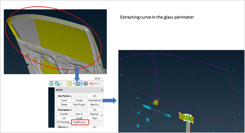
CBUSH Connection for weather strip at the glass:
The connection at the sliding glass and rigid glass shall be established by performing the following steps.
- Extracting the curve from the glass perimeter as shown in below image.
MESH>Perimeters>Feat2Curve
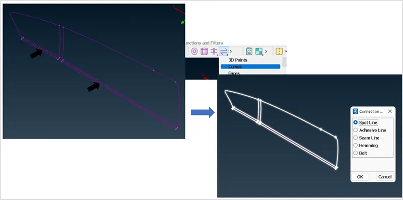
- Offset the bottom curve on both sides as shown and convert these curves to spot line one by one.
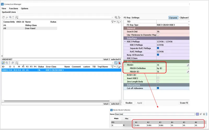
3.Using the connection manager the CBUSH connection is established by selecting the requirequired parts and options in the FE representation settings. In this case, a PBUSH ID must be created and the damping coefficients must be entered.
Upon applying the above settings, we can realize the Cbush connection as shown in following picture. These connections must be established one after the other to get the proper connectivity between the relevant parts.
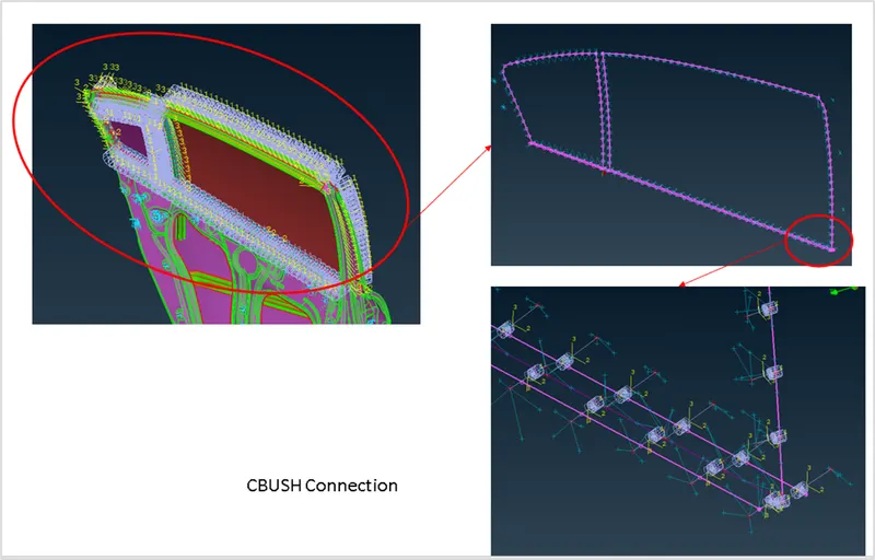
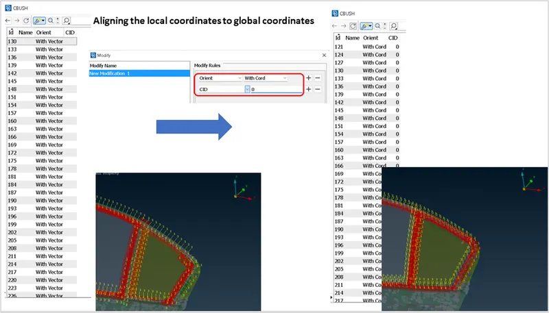
The best practice is to align the local coordinates of the CBUSH conenction to global coordinates and it can be done as shown.
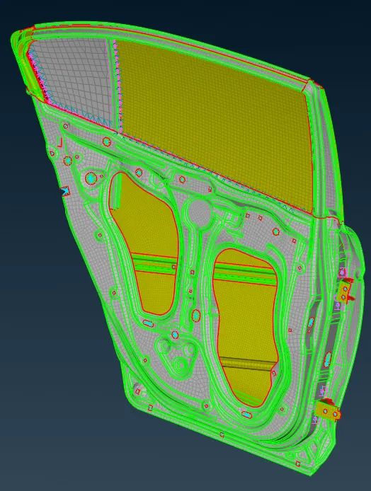
Finally, we have established all the connections in the rear door model.
Conclusion: Thus the different connections were provided and studied.
Learnings:
- Understanding on 1D elements
- Understanding on different types of connections and how to establish in ANSA.