Week 6 - Creating connection for Rear door
Aim:
To provide appropriate connection to the given back door model using NASTRAN deck in Ansa.
Procedure:
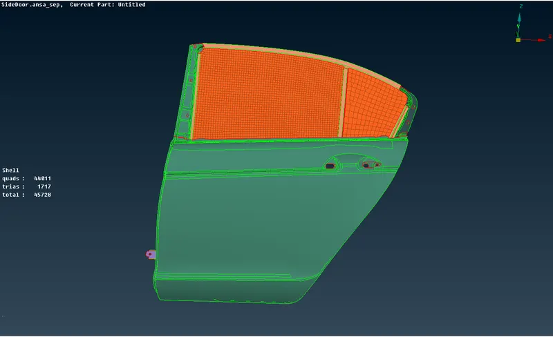
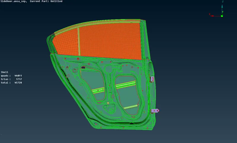
1. The given FE model of the back door contains only one PID, so first we needed to Separate it into different PID's appropriately.
2. Then we need to check the model thoroughly after which we can proceed with the connections.
Connectors:
Depending up on the model requirement various types of connectors are used, Such as many node RBE2, Two node RBE2, Cluster RBE2, weld and bolt connectors
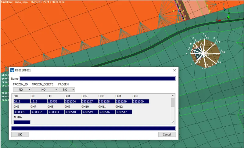
3. RBE2 connections:
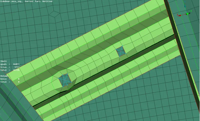
- In this type of RBE2 connection we can provide connection to two or more holes on two or more surfaces which are nearer to each other and lock the in All Dof's and axes so that they cannot move which makes them rigid during the NVH simulation.
The following Steps are followed in creating a RBE2 connection.
NASTRAN deck `rarr`Elements `rarr`RBE2 `rarr`Many nodes `rarr`Select slave nodes `rarr`Select master nodes `rarr` Finish
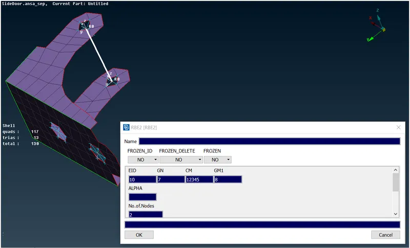
- To make connection to the hinge of the door we need to create Two many node RBE2 on the opposite holes using the command mentioned above, with the master nodes of the created many node RBE2 we need to create a Two node RBE2 using the Following command.
NASTRAN deck `rarr`Elements `rarr`RBE2 `rarr` Two nodes `rarr`Select slave nodes `rarr`Select master nodes `rarr` Finish
Sice the door needed to be opened we should not locked it in all Dof's
- Cluster RBE2 can be used to connect two sub assemblies which have motion that needed to be Constrained. the following command selected
NASTRAN deck `rarr`Elements `rarr`RBE2 `rarr`Many nodes `rarr`Select slave nodes (Nodes from both the sub assemblies needed to be selected)`rarr`Select master nodes `rarr` Finish
4. WELD Connection:
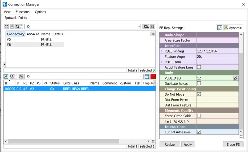
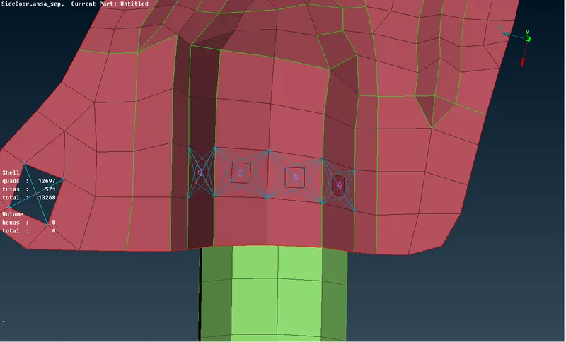
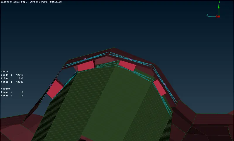
- Weld connection is created between two component in order to give rigid connection where ever it is required.
- Commonly in order to create a weld we need to create a point using the command Points `rarr`In cog option in topo module, since we are having only FE elements
- Then the point is converted into Spot weld points using the convert option.
- After that we need to realize the connection by selecting the Connection Selection Assistant in menu bar which prompt the user to select the two parts which are needed to be welded together
- In FE representation type RBE3 Hexa RBE3 is selected, with a search distance of 20 is given.
- Also we need to create the PSOILD for the weld to be Created in order to achieve a proper connection.
- After Inputing all the necessary paramaters we needed to realize the weld.
4. Connection For Door Handles.
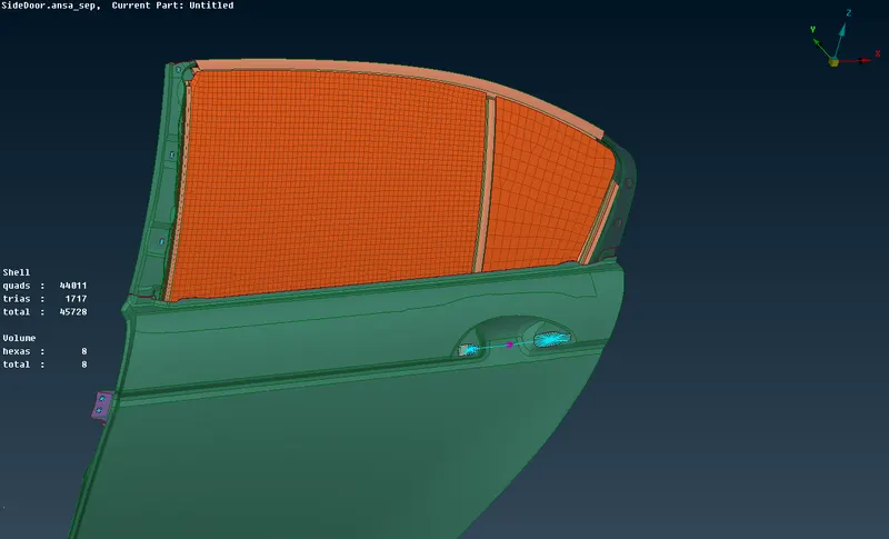
- Since we already knows door handle carries a particular amount of mass, so wee cannot simple define this connection as a massless rigid
- In order to create the connection similary steps followed in creating a many node RBE2 connection is followed
- Once the connection is created another many node RBE2 connection is created between the two master nodes created during the previous steps.
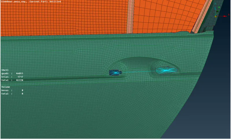
- To assign mass to the door handles we need to assign CONMi `rarr`CONMi2 at the master node of the RBE2 which is at the center.
5. BOLT Connection:
- Bolt connection is created between two component in order to give rigid connection and to remove the connection where ever required.
- Commonly in order to create a weld we need to create a point using the command Points `rarr`In cog option in topo module, since we are having only FE elements
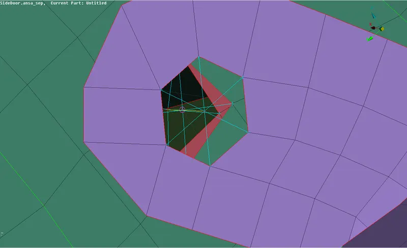
- Then the point is converted Bolt points using the convert option.
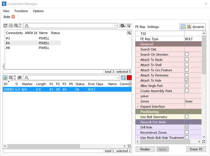
- After that we need to realize the connection by selecting the Connection Selection Assistant in menu bar which prompt the user to select the parts which are needed to be bolted together
- In FE representation type Bolt is selected, with a search distance of 20 is given, also the body type is selected as RBE2
- After Inputing all the necessary paramaters we needed to realize the bolt connection.
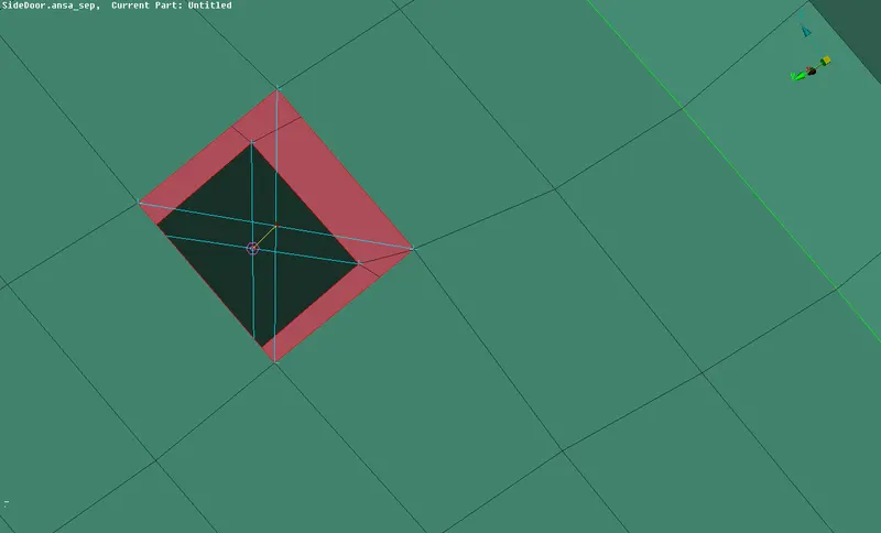
6. Window Bushing Connection:
- Here the bushing i.e., weather strips are connected to the mirror using spot line connection option in order to create the spot line connection option first we needed to create a line throuhout the out line of the mirror.
- The line is created using the option Feat2Curve available in the Perimeter menu of the mesh module.
- Once the curve is created , it should be converted into spot line using the Convert option available in the menu bar
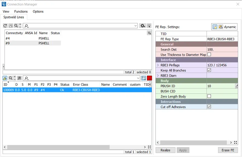
- After that we need to realize the connection by selecting the Connection Selection Assistant in menu bar which prompt the user to select the two parts which are needed to be connected together
- In FE representation type RBE3 CBUSH RBE3 is selected, with a search distance of 20 is given.
- After Inputing all the necessary paramaters we needed to realize the weld.
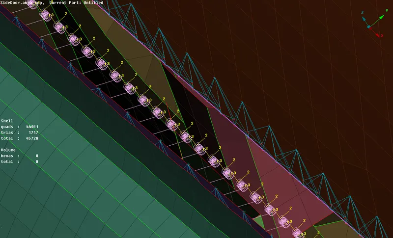
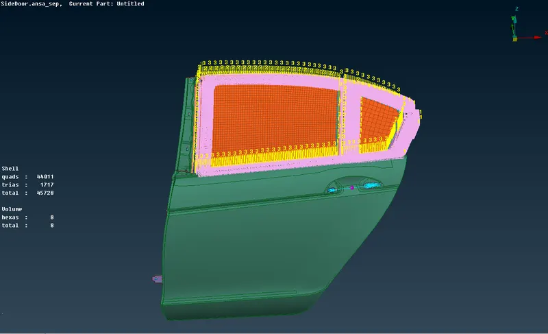
- After making the conncetion the CID is needed to be set to zero and Orientation is to be selected as With cord to make the bush linear to the global axis.
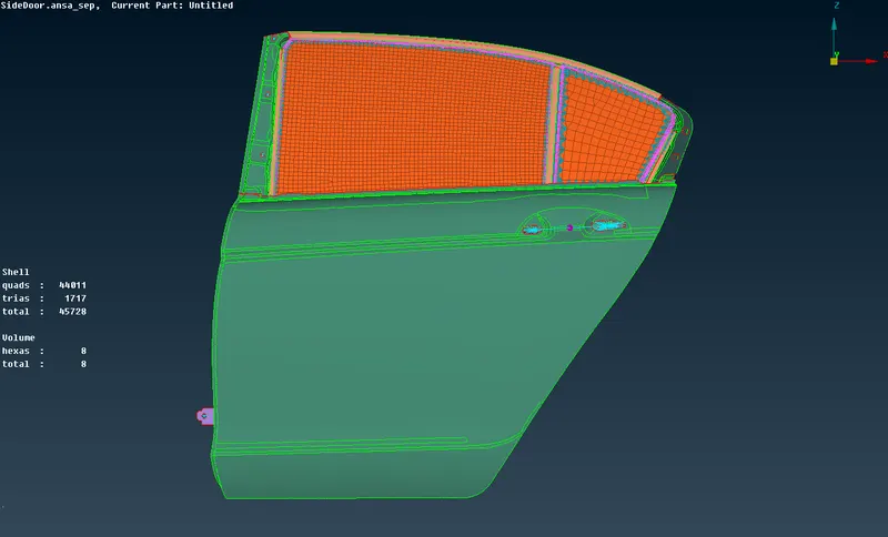
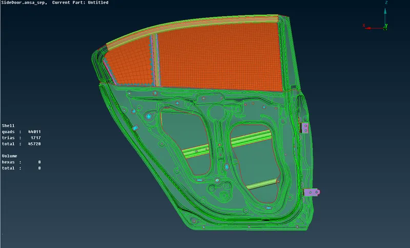
Final Model Image:
Learning outcomes:
- When to use cluster and stem representing a bolt connection
- How to connect two parts using a spot weld representation.
- How to connect the glass and weather strips using Cbush elements.
- How to represent a Door handle and provide the mass of the handle.
- How to connect door hinges with correct Dof's.
Conclusion:
The Connection of the rear door assembly has been done and the necessary parrts have been connected using the NASTRAN deck in ANSA