Week 6 - Creating connection for Rear door
1. AIM: Creating a Connections for Rear Door FE model.
2. OBJECTIVES OF THE PROJECT:
For the given Rear Door FE model, Create and Apply different PIDs for different components and Generate suitable connections between Parts.
3. BODY OF THE CONTENT:
Let's First Import the Given part in ANSA.
- IMPORTING THE FILE: Importing the given SideDoor.ansa file using a path file > open
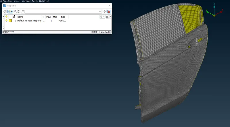
Fig: 01 SideDoor.ansa
After the importing model the first step is to check the geometry error in the model, but as this is a FE model, this step will skip.
- CREATE A PIDs: As can see the Model comes with FE element only. There is no parent geometry. The whole model has a one combined PID only can be seen in Fig 1. So, I need to separate it into different PIDs for different parts. As per Below fig. Can see the result after creating different PID.
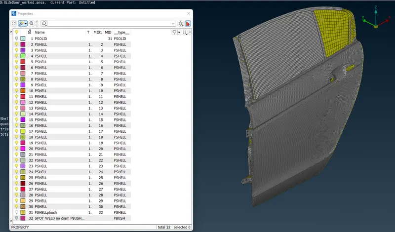
Fig: 02 Model with Separate PIDs
Now, Next step is to create an appropriate connection between those parts.
- REALIZING CONNECTIONS: After Analyzing or Visualizing the features available in parts, we can predict which types of connections can be used. As for this model RBE2, RBE3-HEXA-RBE3, RBE3-CBUSH-RBE3, CONM2, Bolt_Type & Spot weld type such connections will be used. Let’s get into detail.
- Door Hinge: Let’s start with Door Hinge connection. As we know the door is connected with the car through a hinge connection, So those connections will be made as a rigid connection using RBE2 method. Procedure is first activate the command, then select the nodes or elements to make rigid, then go with the next button and choose the applicable options like CM and Part. where CM is indicating the degree of freedom. For a total of six degrees there are numbers from 1 to 6. Where 123 is for linear constraints and 456 for rotational constraints. Here as per the Side Door moment in the car, the ‘6’ constraint will be removed from the value. So the final input will be 12345 and for zero freedom 123456 will be used.
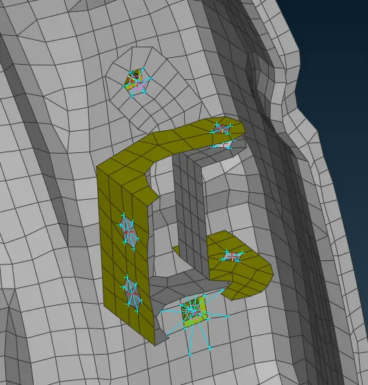
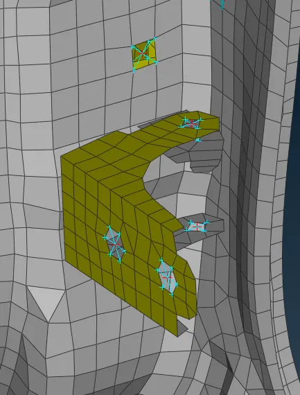
Fig: 03 Connection made at Hinge
As can be seen, Hinge is bolted to the door. So, bolted connections are created. Can be seen in the above fig. To define the Bolted connection, First need to create 3D point at location (in TOPO > Points > On COG), then Convert 3D point into Bolt (in Assembly bar > Convert > 3D points > select point > In Connection type window, select Bolt), Now need to define that bolt with the PIDs as per its connections through it (In Asselby bar > Connection manager > select created Bolt > hit MB3 > connection manager will open). In the connection manager we can select a maximum of 4 PIDs. For current connection P1, P2, P3 defined. And FE rep type ‘bolt’ selected with applicable options. Then hit apply and Realize.
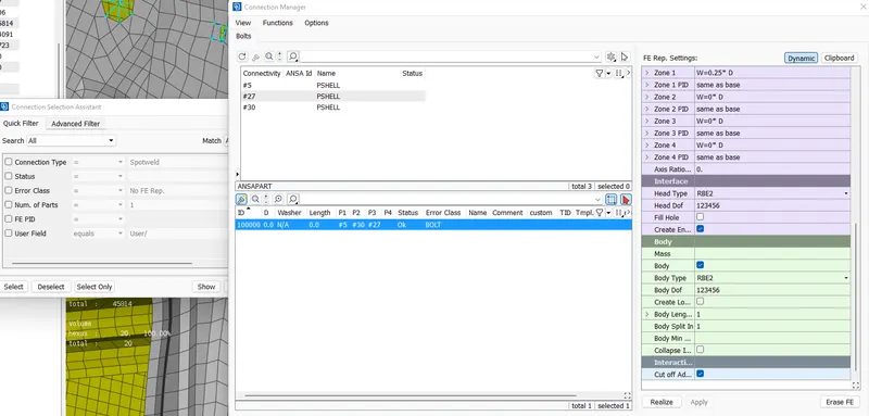
Fig: 04 Connection manager with Bolted type connection
- Rigid connections: Sometimes a hole present between parts will fix with other accessories or some other connection. So at that time we need to simply fix it for all directions. So at that time we will make it rigid through RBE2' method.Can see in below fig. Around 26 locations this type of connection was created. We can see it in blue in the below image.
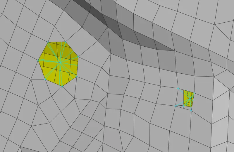
Fig: 05 Rigid connection at Holes between parts
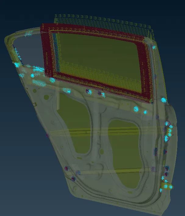
Fig: 06 No of Rigid connection in Model
- Spot Weld type connections: From visualization we can see that some connections should be spot weld type. Can see in the below fig. It's a RBE3-HEXA-RBE3 type of connection. To create a first need to create a 3D point > Convert > convert 3D point to spot weld connection > then open Connection manager and define a PID, then select FE rep type > RBE3-HEXA-RBE3 > and fill with appropriate options (like, search distance, RBE3 pinflags 123456, PSOLID) > apply > realize. As in fig number we can see that around 21 spot weld created as needed.
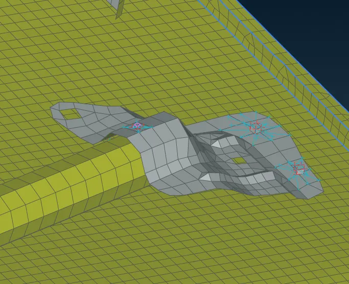
Fig: 07 Spot weld connection at between parts
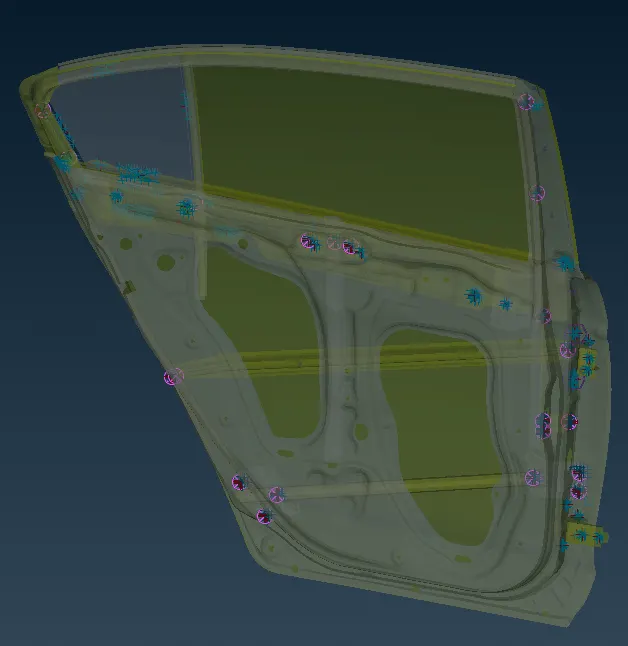
Fig: 08 No. of Spot weld connection
- Door handle: Door Handle type parts in Side door like, Window Switch, Window regulator, Door Speaker, Door switch, Lock & Latch etc. who has some weight. For these types of part connections we simply connect it with a rigid connection using RBE2 > many nodes and using RBE2 > two node, making one element common. On that element we apply component weight using the CONMi function.where M is mass in kg.
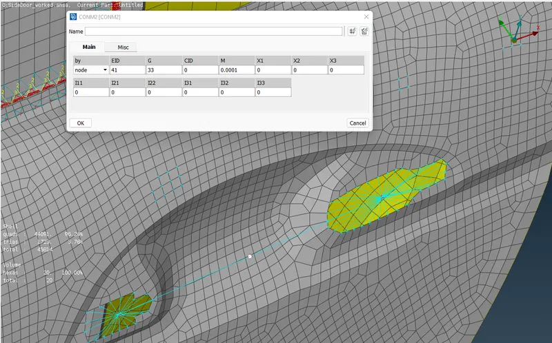
Fig: 09 CONMi connection in Door handle
- Door Seal & Weatherstrip: At this location where the window glass is not in fixed position, So to define this type of connection we use RBE3-CBUSH-RBE3 type. First we have to create a spot line using Feat2Curve > Convert > Curve > Connection type > Spot Line > Connection > select a spot line > same process here to define a P1, P2, > FE Rep Type select RBE3-CBUSH-RBE3 > define search dist, PBUSH > Apply > Realize. Where I need to enter the stiffness value in PBUSH ID.
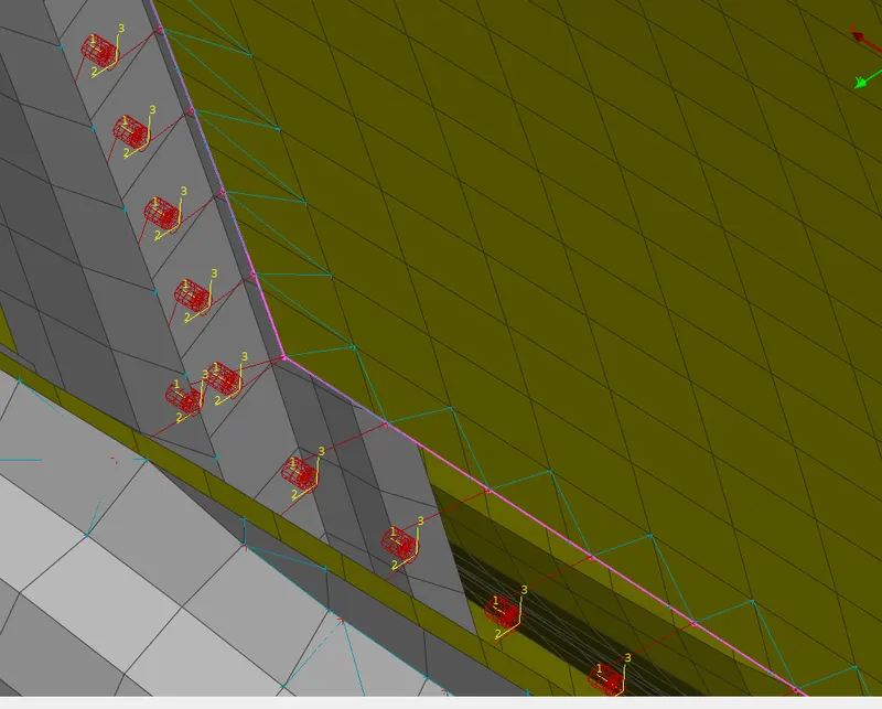
Fig: 10 CBUSH connection for Glass window
At default CBUSH will apply with the default coordinate system as per part connections, but for ease and to save time in simulation, all CBUSH connections are made in the Global coordinate system of Model. In Image we can see that all are in one direction.
4. LEARNING OUTCOMES:
The Purpose of this challenge is to define connections to the model. I Learned that how connections are defined in ANSA using the NASTRAN domain in the assembly model. Where I learned how and which types of connections should be used in a model. A Parent geometry should be present with a model to choose a connection type correctly.
5. CONCLUSION:
Finally the challenge is completed. This challenge is a practice model for make a connections. That covers around six types of connections in the Side Door model.. After this challenge, I’m able to see which types of connections can be used in the assembly model. One thing is to remember is that we have to think from simulation perspective while making connections to ensure all parts are defined with necessary connections otherwise getting a wrong result or getting a free moving part.