Week 6 - Creating connection for Rear door
Aim:- Creating 1D connections using NASTRAN deck for given Rear door of car FE model.
Objective:-
* Create and Apply different PIDs for different components.
* Perform suitable connections using 1D element for given model.
Procedure:-
Import the model:
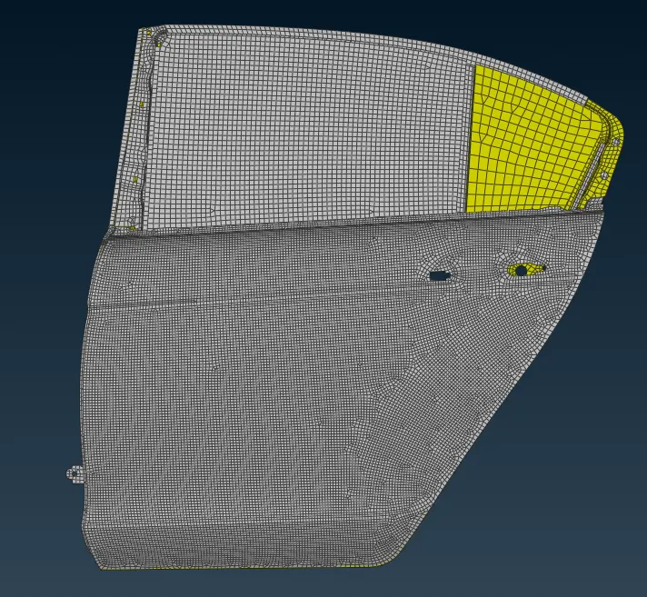
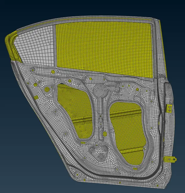
* First we import the model in ANSA ( file - open - select file - ok )
Segregate the model according to PIDs:
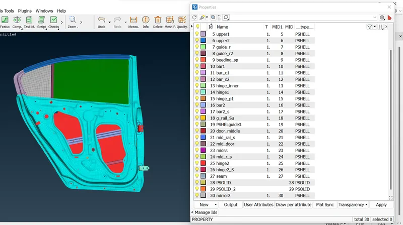
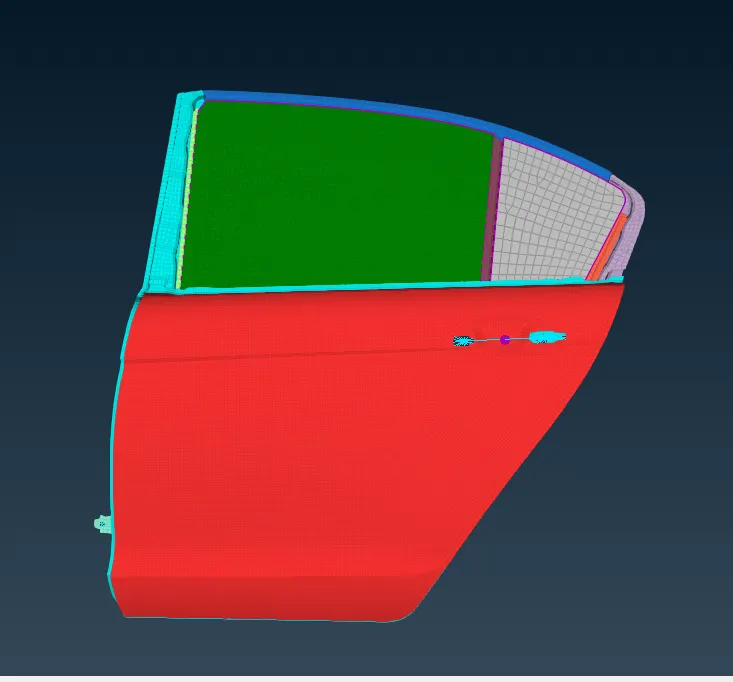
* The given model has only one PID , so in order to give connection and realize them we have to segregate model into different PIDs according to components.
* For this task we use set PID tool to create PIDs for components. ( mesh - macros - set PID )
* We use PID region selection tool for this operation.
Creating Connections:
* First create the bolt connections.
* We check and observe the model and decide where we do bolt connection.
* The hinge part is important part connected with the outer surface of the rear door connected with the outer body of the vehicle has given the rigid connection of bolt as RBE2 elements.
* There are several ways to present the bolts.
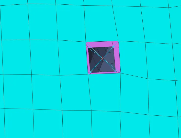
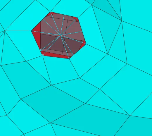
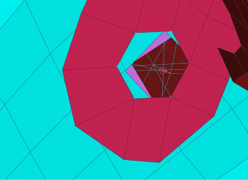
- by creating RBE2 cluster.
* In this method we create RBE2 elements in between 2 or more holes.
* We select node of hole by loop selection and create cluster. ( NASTRAN deck - elements - RBE2 - many nodes )
* Below image shows that the creation of bolt with RBE2 cluster.
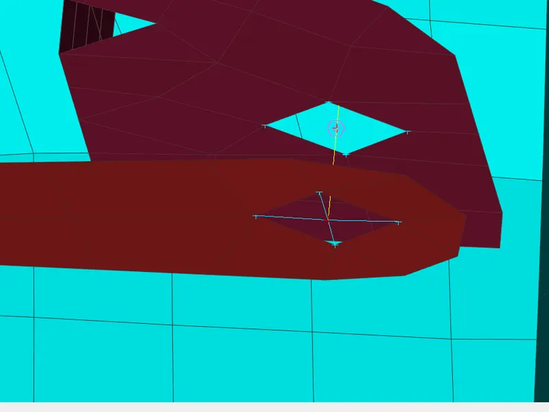
- by creating RBE2 spider in each hole and between them 2 node RBE2 element.
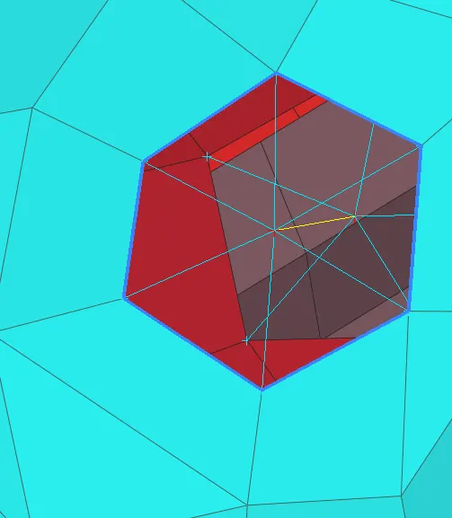
* In this method we create a spider of RBE2 elements in each hole.( NASTRAN deck - elements - RBE2 - many nodes )
* After that we create a two node RBE2 element between the spider of hole which acts as a bolt body (stem ). .( NASTRAN deck - elements - RBE2 - two nodes )
* In below image we can see that the bolt is created.
- Automatic bolt creating through 3D point.
* In this method first we create the COG point in any one hole. ( topo - points - COG -egdes )
* After this convert this 3D point to bolt by convert tool. ( Assembly - convert - select point - bolt )
* Then we go to connection manager and select this bolt symbol and open connection manager.
* First we select parts by right click on p1 and then left click on box and then click on F1 and select parts.
* After this we select the FE rep type as bolt and give search distance.
* After this we select zones and click on apply and realize.
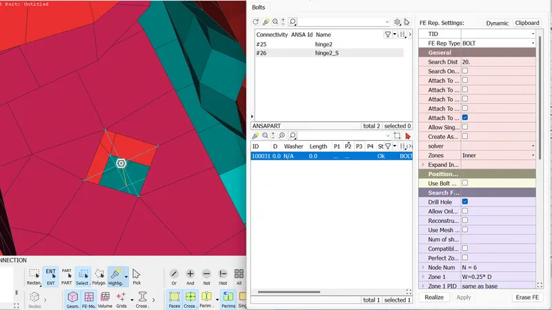
* In this connection we select inner zones but we can also select in/out or other options.
* Below image shows that the bolt connections we created in the given model.
Providing DOF for opening the door:
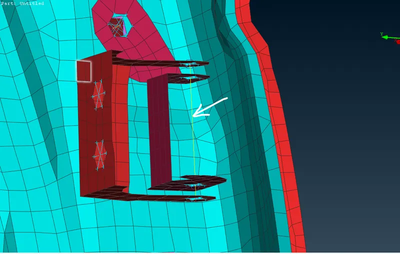
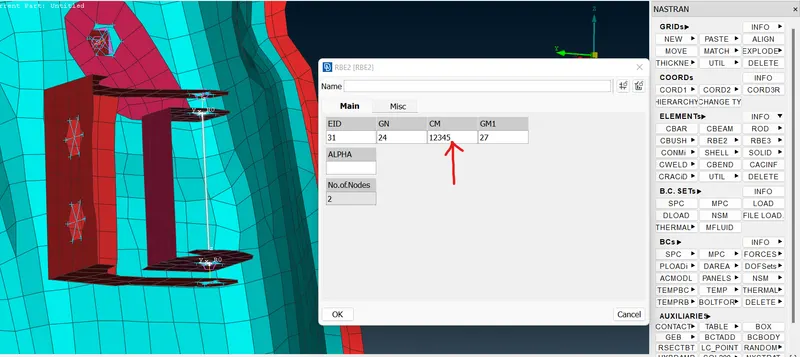
* The door is moving part of the vehicle body and in simulation process it act as a car door open in required direction. to have a correct connection to the hinge part which connected the door with vehicle body , we have to provide Z-axis rotational movement by removing DOF of it.
* For this we create a 2 node RBE2 element in between hinge as shown in below image and remove the y-axis rotational DOF of this RBE2 element.
For door handle :
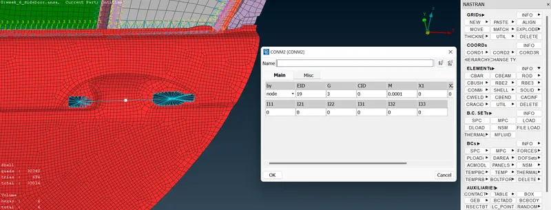
* In this region, we need to create a connection that applies a mass (to represent the handle). For this, we need to create RBE2 cluster in each handle holes separately (NASTRAN DECK - Elements > RBE2 > Many Nodes). After this with same tool we create a 2 node RBE2 element between these two holes , due to this a master node is created in between two holes and in this master node we apply a mass.
* For applying mass we use nastran deck and in elements we use CONMi - CONM2 - nodes Then the previously mentioned master node is selected. This is where the mass of the handle will be concentrated. After proceeding, the algorithm lets us assign the mass
* After bolts we create welds connection ( seam and spot weld )
* We observe the model and check where we can use seam weld and where spot weld.
* After deciding we go to connecting parts with seam and spot weld.
FOR SEAM WELD :
* There are two types of seam weld
- 1st is overlap shell joint - used when parts are parallel to each other.
- 2nd is y-joint shell : used when parts are perpendicular or inclined.
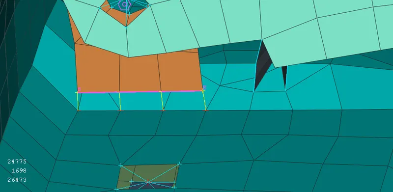
- we can also used seam weld with RBE2 Element.
* In given model there is no data given for welds so we have to generate the weld data from FE model.
* For generating the weld data we create curves from FE model. ( Mesh deck - Perimeters - Feat2Curve ).
* Then we convert this curve to seam line by convert tool. ( Assembly - convert - curves - seam line )
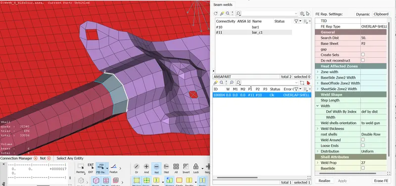
* After the conversion of curve we proceed to create seam weld , for this we go to connectin manager and select this created seam line and open connection manager after this we select parts and then select the FE rep type as OVERLAP-SHELL ( Because our parts are palallel to each other ). The root shell option would be 'double row'. Other properties (such as width or thickness) and PID can be assigned for the weld as well if needed.
* We created the property for seam weld by clicking shift+/ in weld PID box and create the property.
* In this way we create the connection using seam weld.
* Representation of seam weld is shown in below image.
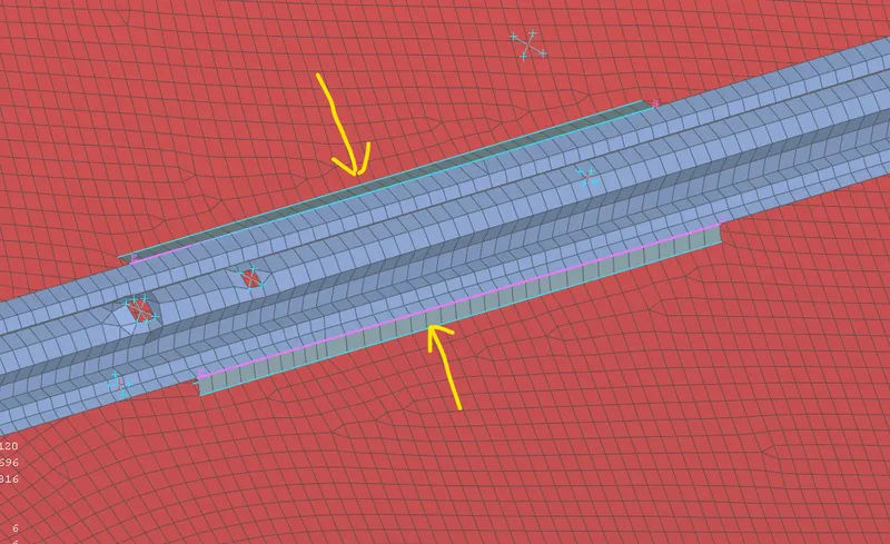
* In below image the seam weld with RBE2 element is shown.
FOR SPOT WELD :
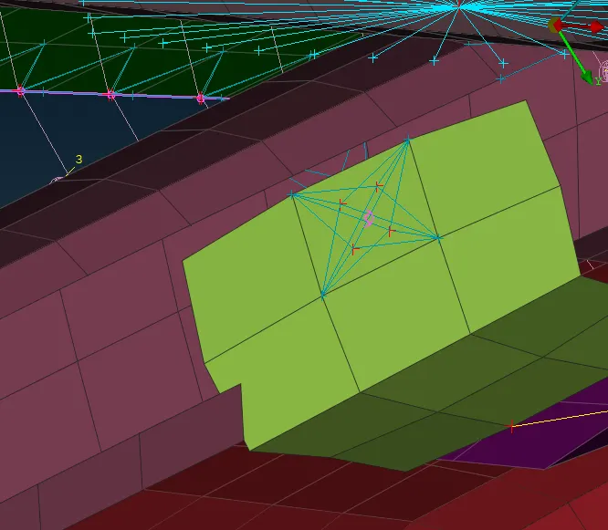
* For spot weld we creating 3D point using COG tool and these 3D points are then converted into spot weld.
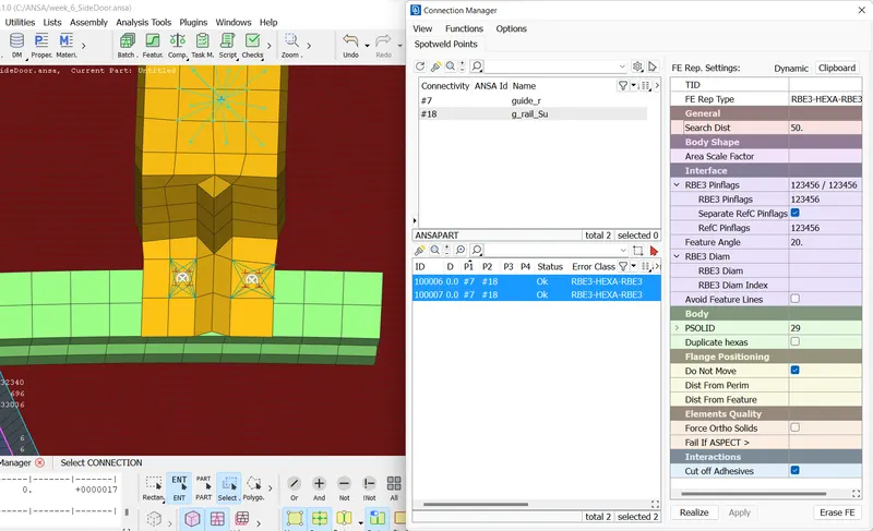
* After this we open connection manager and select newly created spot weld point and then select parts which we have to joint by spot weld , after this we select the fe rep typer as RBE3-HEXA-RBE3 , after this RBE3 pinflags should be constrained in all D.O.F.s. Furthermore, a PSOLID will need to be created and assigned.
RBE2 Connections:
* For RBE2 connectins we selects nodes of parts and create the connections. we can create two node connection as well as many node RBE2 connectins. ( NASTRAN deck - Elements > RBE2 )
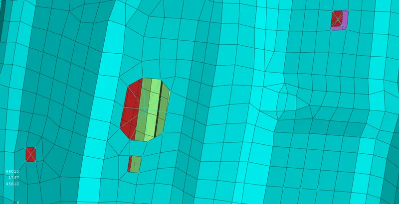
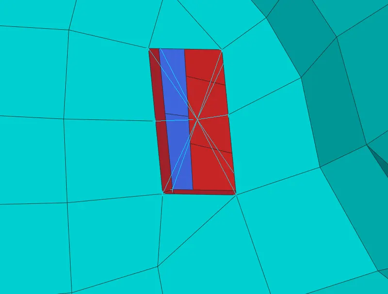
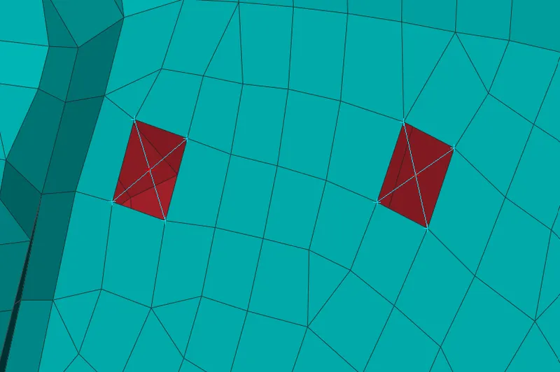
* we have to connect the rail mechanism to the glass of door for up and down motin.
* For this we used 2 node RBE2 element.
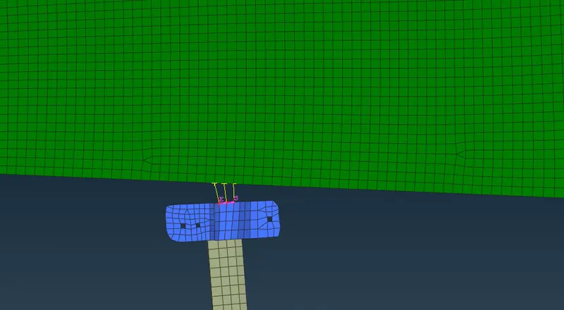
CBUSH Connectin :
* This connectino is used for window weather strips in which window glass is done it's up and down motion smoothly.
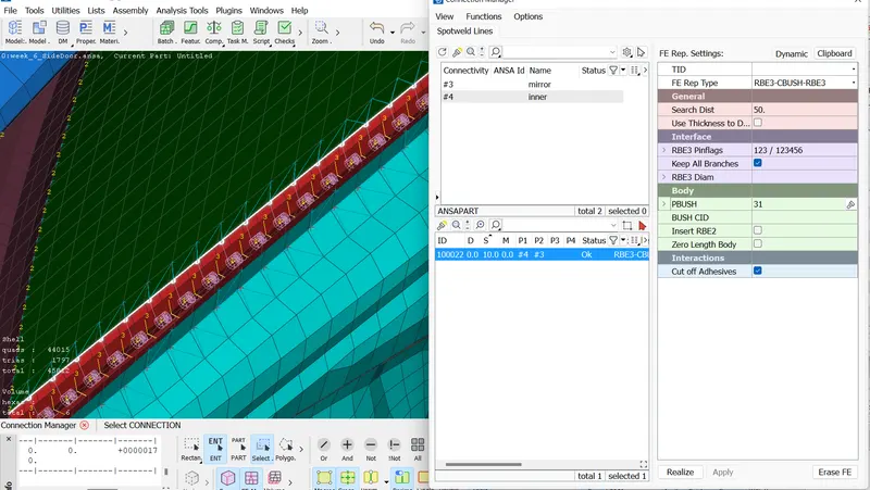
* For this connection we create curve from FE model and in base we copy the curve and transform this curve to 10 mm outside so that we create cbush connection on both sides. ( mesh - perimeters - Feat2Curve ) ( transform - copy )
* Then we convert each curve line separately to spot line.
* After converting them, we open connections manager and give the spacing value of bushes as 10mm then select parts and select the FE rep type as RBE3-CBUSH-RBE3 , check the box of keep all branches after this create the pbush ID after this click on apply and realize. The process will be repeated for each curve. and create the PBUSH connection for all sides.
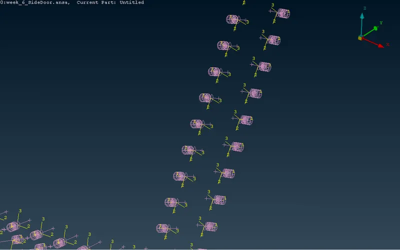
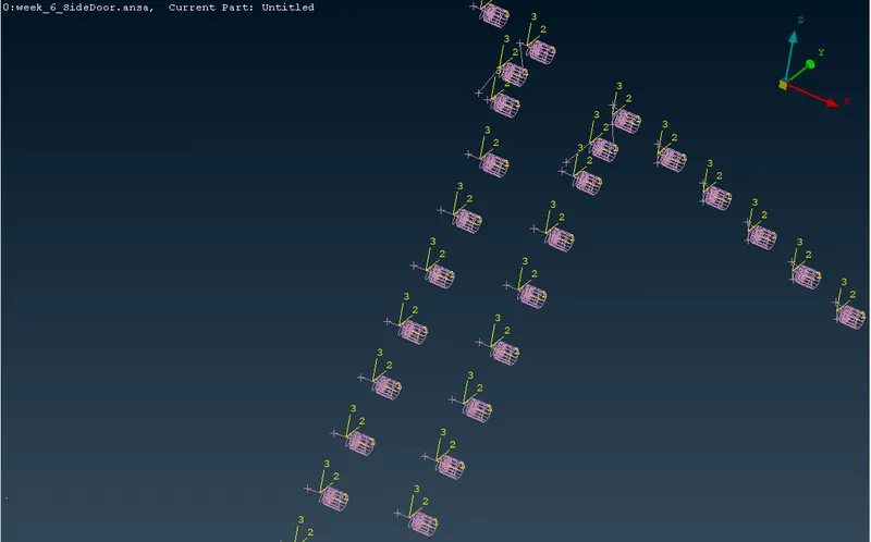
* After this process is repeated for each spot line created, we need to reorient them since they use a local coordinate system which is different from the global coordinate system.
* For fix this issue we cheange the coordinate system of all cbushes same as global coordinate system.
* We go to Database > Elements > CBUSH. All the CBUSH elements are displayed. search orient and then They are selected and then right-click > Modify.
* A modify window comes up where we can add modifications to apply to all the CBUSH connections.
* In the Modify Rules section, we can add the 'orient' rule and assign the 'With Cord' option to it.
* And then click on + button and add 2nd rule , in this we set CID rule and create with value 0 and assign.
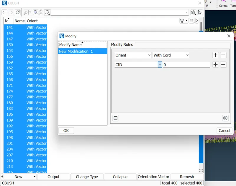
* In this way we aling the coordinates of all Cbush same as global Coordinate system.
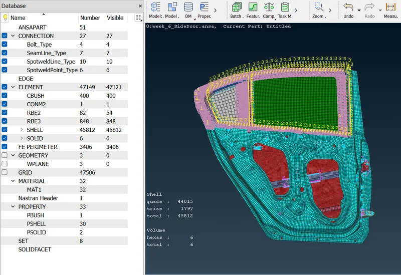
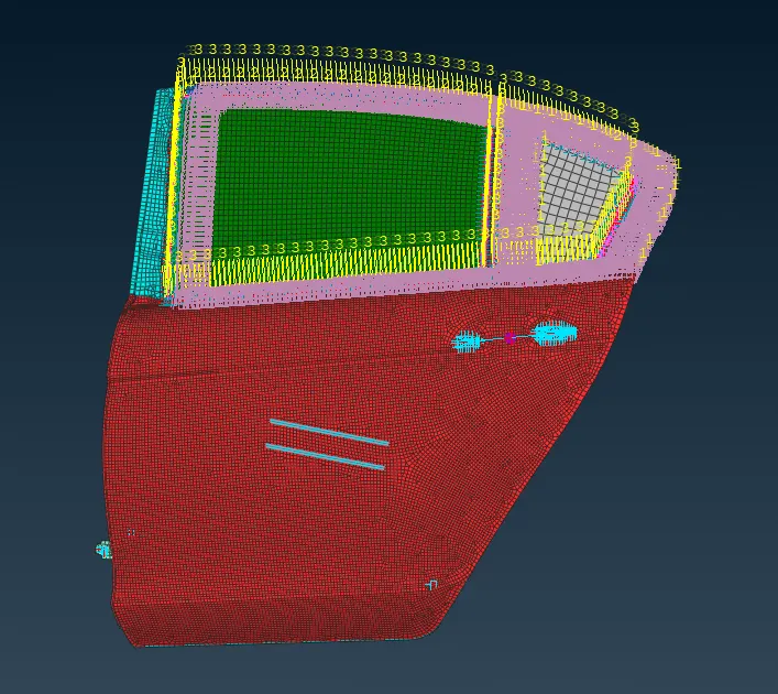
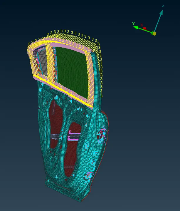
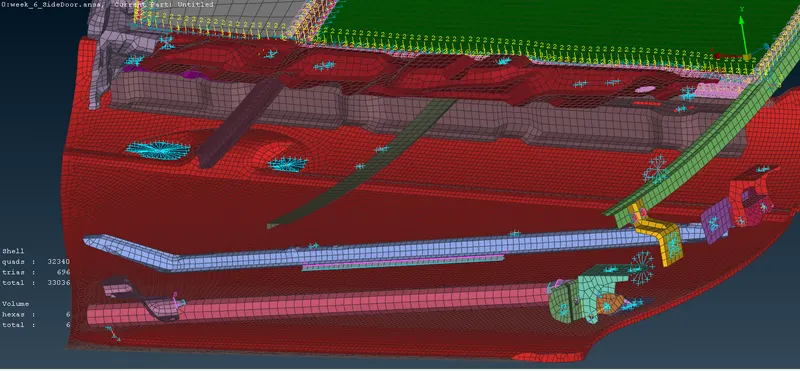
Final Model With All Connections:-
Learning Outcomes:-
* Undrestood various connection are available to connect the parts in FE model.
* Learned different tools like Feat2Curve , Assembly tools.
* Learned how to give connection and how to realize it with proper requirements.
* Understood accurately the concept of Spot and seam weld and CBush connection.
Conclusion:-
Connection of given rear door of car model is successfully done with required conditions.