Week 6 - Creating connection for Rear door
Understanding the basic types of connections, where to use
these connections to make constrains and how to connect
the parts by using different connections and their uses.
OBJECTIVES :-
Understanding different types of connections.
Different methods to implement these connections.
How to form a weld and bolt connections.
PROCEDURE :-
There are two steps to be followed for deploying the connections,,
these are,
Creating New PID's
Deploying Connections.
CREATING NEW PID's :-
The input FE model is opened using the command
file > open.
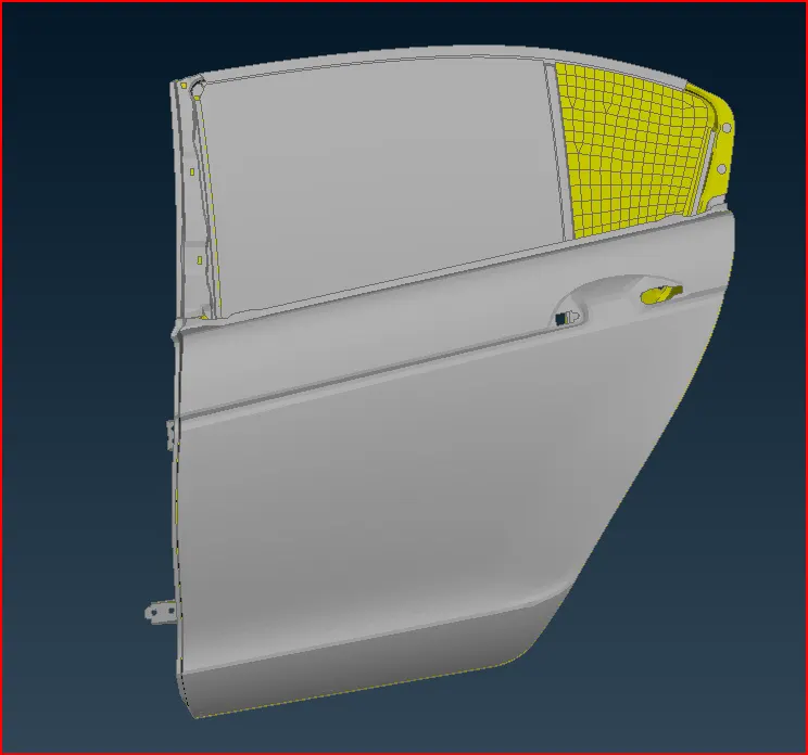
fig. Import model
The whole side door is stored in a single PID and that is to be seperated using the
command.
Menubar > modules > Faces > Set > PID
After importing the model we have to create the PID's for different part.
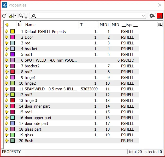
fig.Creating PID's
The Purpose of creating PID is during the time of deploying connections
the starting and ending points of the connections should be mentioned.
DEPLOYING CONNECTIONS :-
For the component connections like Bolt, Spotweld, C-Bush and RBE2
are used in the model.
BOLT CONNECTIONS :-
The function of bolt connection is to generates Bolt connections between
two or more holes, either of shell or solid mesh. The user determines the
element types for the head, body and nut of the Bolt, by selecting among
the provided options. The specified elements of the head and nut connects
the center of the hole to the nodes of selected edges while the body is created
between the two centres of each hole.
The demand for creating bolt in the hole area is,
Topo > Points > On COG option and select edges of the hole to create a
point.
After creating a point ,
Menubar > assembly > convert > 3D points and select a point and select
a Bolt connection type.
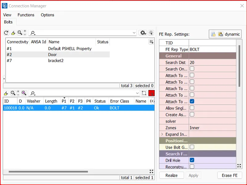
fig. Bolt connection
Then the connection manager tab is opened by the command,
assembly > connection manager > Select the connection.
The above mentioned tab named as connection manager is opened.
There the FE representation is selected as bolt connection and option
like search distance, zones and DOF for the bolt connections are made.
The top left side of the tab contains the input components for the bolt
connections named as P1, P2 P3 are selected. Maximum number of components
for the input are upto P4. Finally realise the connection.
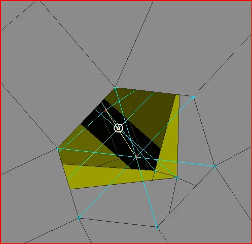
fig. Bolt connection
The head and nut are connected with the body of the . Then repeated
the same procedure for other entities in the model.
SPOTWELD CONNECTION :-
The command for the spotweld connection is,
Topo > Points > On COG option and select edge of the hole to create
a point.
After creating a point, Go to the Convert option and select a point and select
a spot weld point connection type.
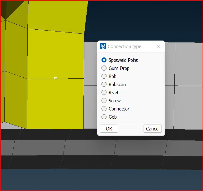
fig. spot weld point
Go to the connection option and select the spot weld point and click ok,
connection manager window will open.
In the connection manager window, select the part to make a connection
and set it as FE Rep type as RBE3 - HEXA - RBE3, search Distance as 20.
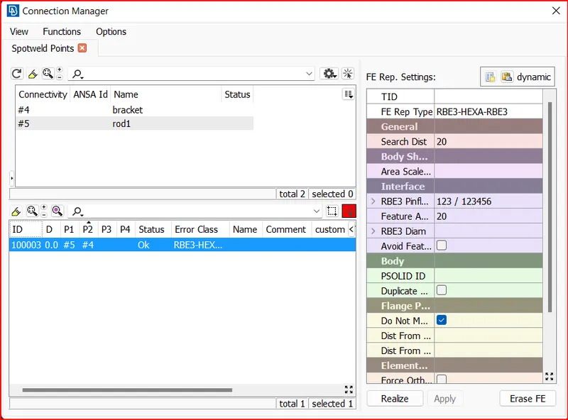
fig. spot weld to RBE3 - HEXA RBE3
The status bar in the window shows all the details about the connections made on the
selected entities.
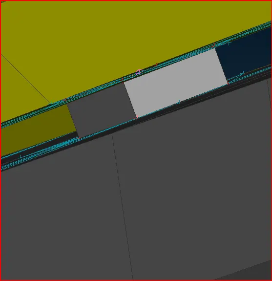
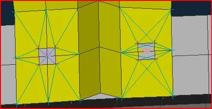
fig. Spot weld and RBE3 HEXA RBE3
The same procedure is followed for all other entities where the spotweld connections
are needed.
Next , we shall focus another weld connection. We shall be looking at seam and spot weld
connections. In the case of seam weld, the basis is creating the weld location from curves
derived from the particular feature. Therefore, we shall be using the,
Perimeter > Feat2Curve option from the mesh deck. This will let us select the edge and derive a curve
from it as shown .
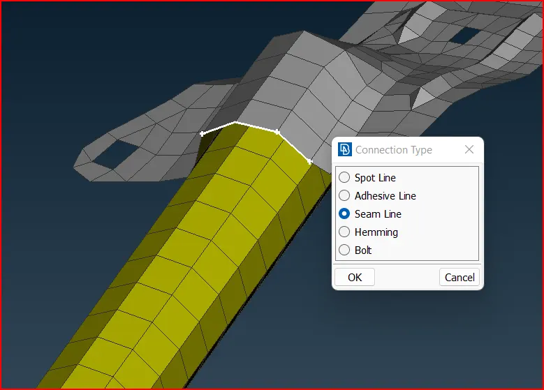
fig. seam line connection
Then, using the same convert tool that was used earlier, the curve can be converted into a seam
line as shown.
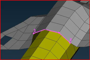
fig.Seam line converted
Again, as before, we make use of the connection manager. The seam line is selected
and on proceeding, we get the same set of options where we need to tell ANSA what
kind of connection we intead on creating. As before, P1 and P2 selected. The FE Rep
type here would be Pverlap shell since both layers are parallel to each other.
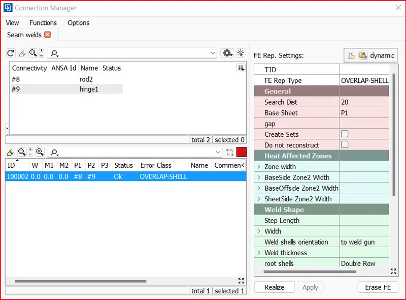
fig. Overlap shell connection manager
The root shell option would be 'Double row' other properties and PID can be
assigned for the weld as well if needed. The resulting weld turns out as follows.
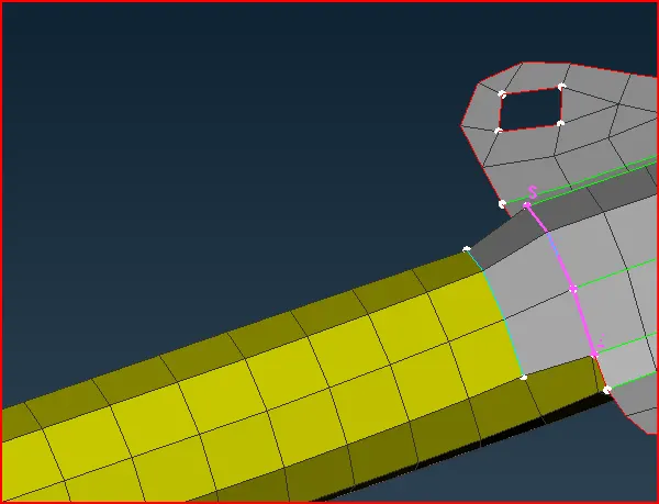
fig. Overlap Connection
CBUSH CONNECTION :-
Go to, Mesh module > Perimeter > feat2curve option and select the edges and create
a curve.
After creating curves, Go to the Convert > Curves option and select a curve and
convert to spot line.
Go to the Assembly > Connection manager option and select the spot weld point
and click ok, connection manager window will open.
In the connection manager window, select the part to make a connection and set it
as FE Rep type as RBE3-CBUSH-RBE3, Search Distance as 50 and Select keep all
branches option.
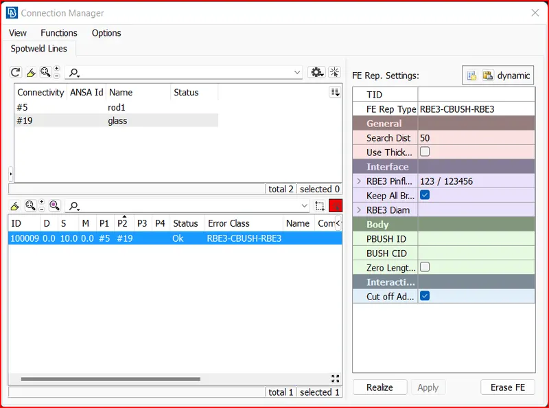
fig. CBUSH connection manager
In the connection manager window, create a PBUSH ID and assign the values for
the property.
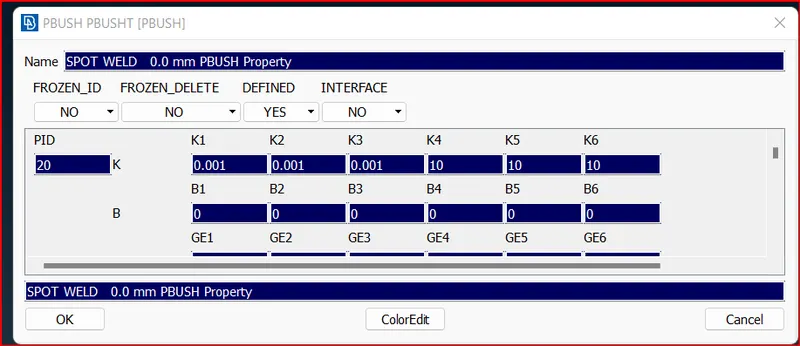
fig. PBUSH value
After setting all in the connection manager window, click apply and Realize.
After creating a CBUSH, Open the CBUSH window from Database and convert orient as with
cord and CID as 0 for all the CBUSH.
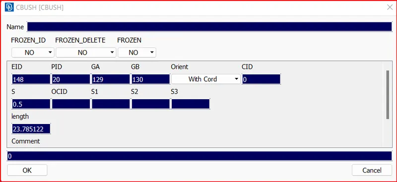
fig. CBUSH value
Finally CBUSH will be created along with the global axis.
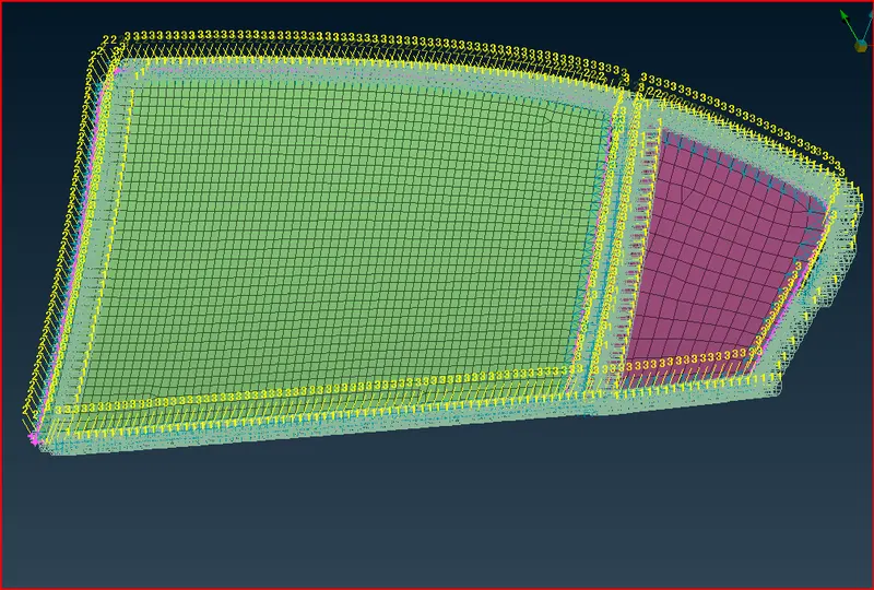
fig. CBUSH connection
RBE2 CONNECTION :-
Connecting all other parts by using RBE2 connection.
Go to NASTRAN Deck > Elements > RBE2 > Many Nodes Option and
select the nodes and create an RBE2 connection.
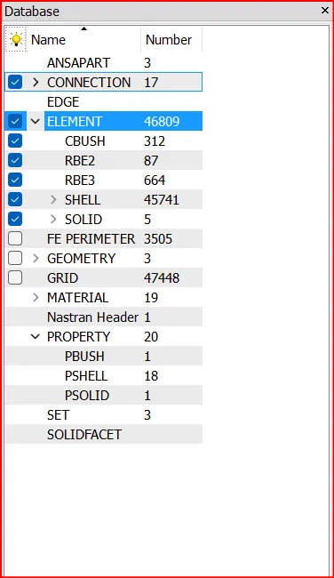
fig. Database
The database shows us all the information about the connections
made in the whole model.
FINAL MODEL WITH CONNECTIONS :-
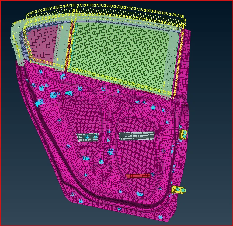
fig.final Image
LEARNING OUTCOMES :-
Different type of connections and their use.
Different methods of generating a single connection.
Which type of connection is to be generated as per the requirement.
Understanding the mechanism and different parts in a door model.
CONCLUSION :-
The given component is deployed with the suitable connections and realised the
deployed connections successfully in the entities. Different methods are used to create
a simple connections and the whole component is connected with the suitable connection
types.