Week 6 - Creating connection for Rear door
MAKING CONNECTIONS FOR REAR DOOR
AIM:
- Creating the connections for the front door by using different 1D elements(Connection types) in ANSA pre-processcing tool
OBJECTIVE:
- For the given Rear door FE model, Create and Apply different PIDs for different components.
- Connections like, Spot weld, Seam weld, Cbush, Bolt has to be done in the Door areas.
- Find the areas and give the proper connection whichever areas needs which connection and explaining the procedures.
GIVN MODEL:
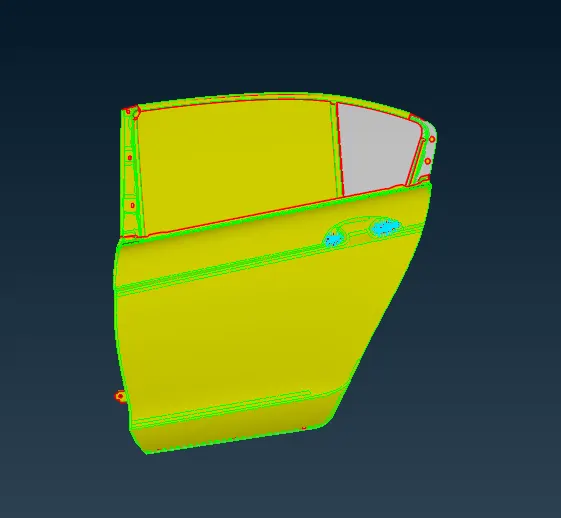
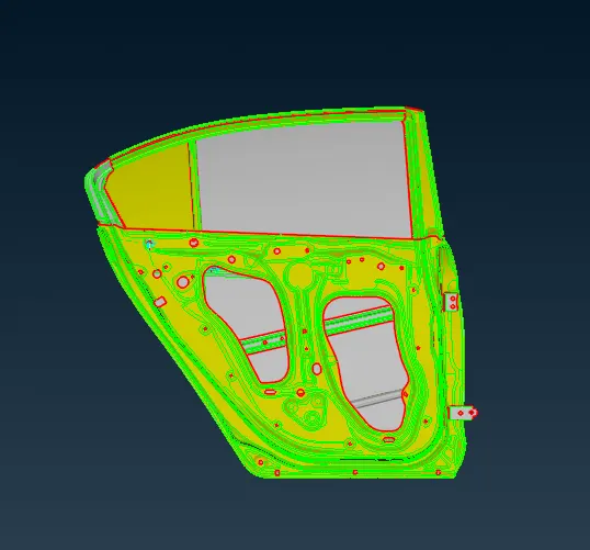
- This is the side door front and back view, To make connections we have to have the FE model, fortunatly the given model is already a Meshed one.
- So we will directly go and make the connections.
CONNECTIONS:
- Connections are nothing but representation of bolts, welds, rigid body, etc. in a FE model.
- Here I have deployed various necessary connections.
- In this FE model, I have used BOLT connection, WELD connections, etc. as per the given cad data also assumed the welded area & deployed weld connections as the seam weld raw data has not given in this model.
- Types of connections used here are,
- Bolt connection.
- Weld connection.
- Seam weld
- Spot weld
- C- Bush connection element
- Concentrated Mass element connection (CONMi)
- All the above mentioned, among other, processes can be easily accomplished through the ANSA Connection manager, a dedicated tool for managing connections.
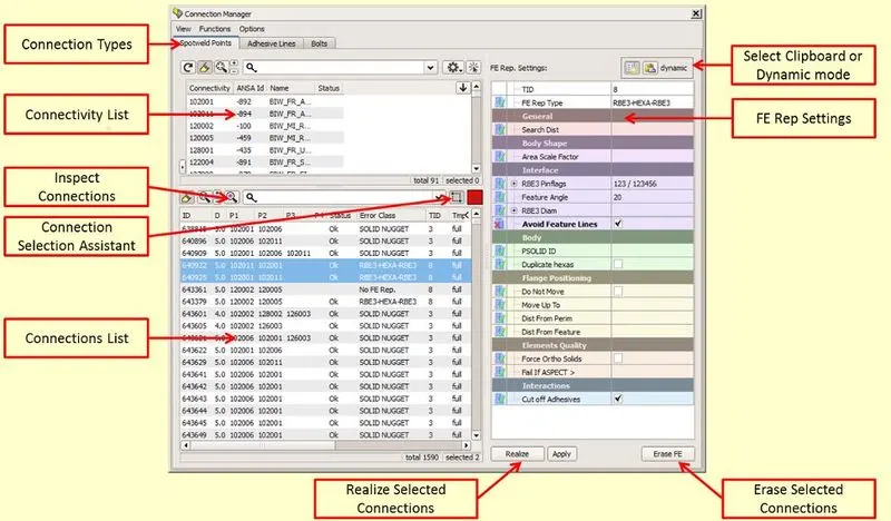
- On the above image we can see the connection manager window and the options also mentioned there.
PROCEDURE:
BOLT CONNECTIONS (No property element)
- Two node RBE2
- Many node RBE2
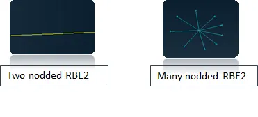
- We can represent the bolt connection in 2 methods.
- Manual method
- Automatic method using Connection manager tool
- In this model I tried both methods.
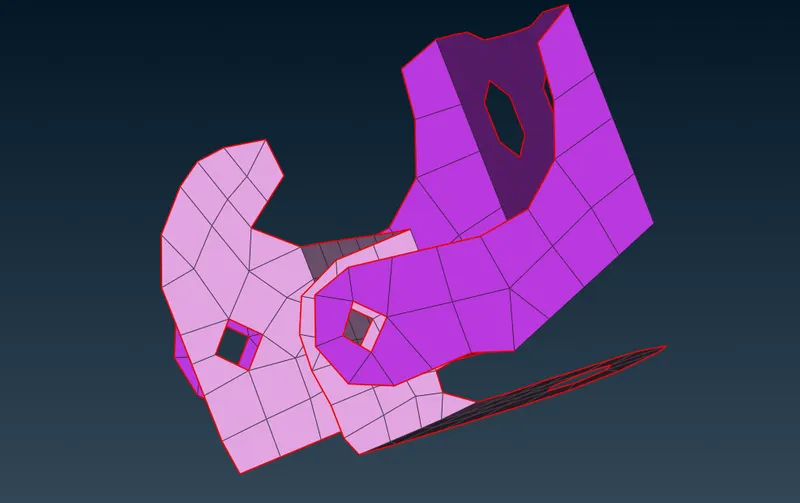
- This is Hinge and Hinge support parts, where we are going deploy the Bolt representation using connection manager
Steps to deploy bolt connections (RBE2 elements)
(Point creation)
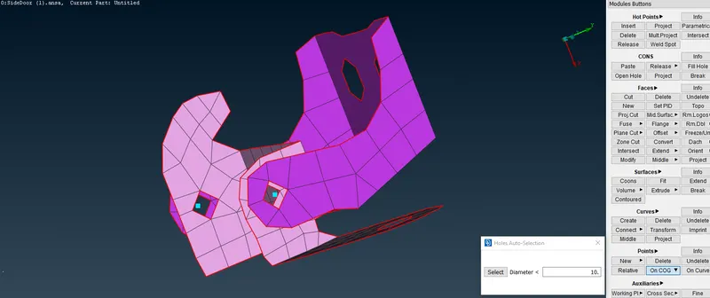
- First we have to create a 3D Point using Topo Module --> Points --> On COG, select the area where we want to create a middle point with the help of Loop selection tool.
- Those square shaped points has created shows in the above image are the 3D points
(Converting the points to Bolt)
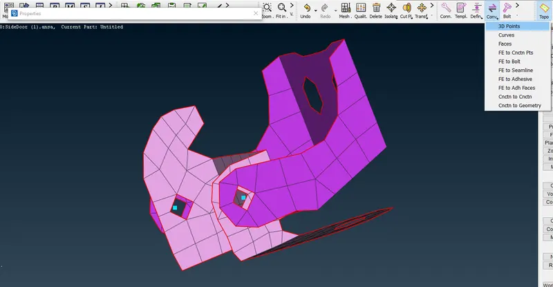
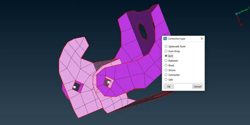
- In above image we can convert those 3D Points into Bolt using the option in 'Assembly tools' area, there we can see a option 3D points
- By selecting it we will see Connection type Pop-Up window, there we can select the Bolt option is show in above image.
- Finally the Points are converted into 'Bolt' representation type, we can see it in above images.
(Bolt connection creation using Connection manager)
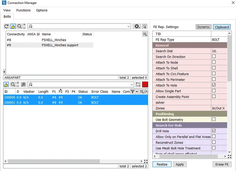
- Bolt created using the connection manager
- We can see the status of Bolt is indicate OK, which means our operation done.
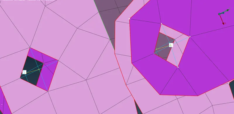
- Those blue lines created, are the RBE2 rigid body elements, that Yellow line(Two node RBE2) is a Stem of the Bolt.
Steps to deploy bolt connections on DOOR OPENING & CLOSING JOINTS
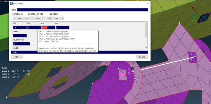
- While deploying Two noded RBE2 element to represent the stem of the bolts at those opening & closing pin joints of doors as shown in below figure has to be free from rotational Z axis.
- The Degrees of freedom for the rotational axis (Z) of a door for opening and closing should not be constrained. So to do that In CM -123456 we have to remove the 6 and the CM - should be 12345 as shown below figure. (CM- DEGREES OF FREEDOM)
- 123 (XYZ) - Linear translation.
- 456 (XYZ) - Linear Rotational.
- Since, here the Z rotational axis should be freed so we have entered CM - as 12345 which means (XYZ LINEAR TRANSLATION & XY ROTATIONAL ARE ARRESETED OR CONSTRAINED).
DEPLOY CONNECTION ON DOOR HANDLE (CONMi)
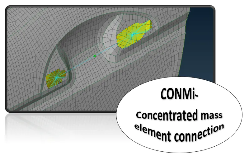
- Deploy Many noded RBE2 element for both the holes separately.
- Again use many noded RBE2 element by selecting the master nodes of two holes on the handle area.
To apply Concentrated mass element connection(CONMi) on Door Handle
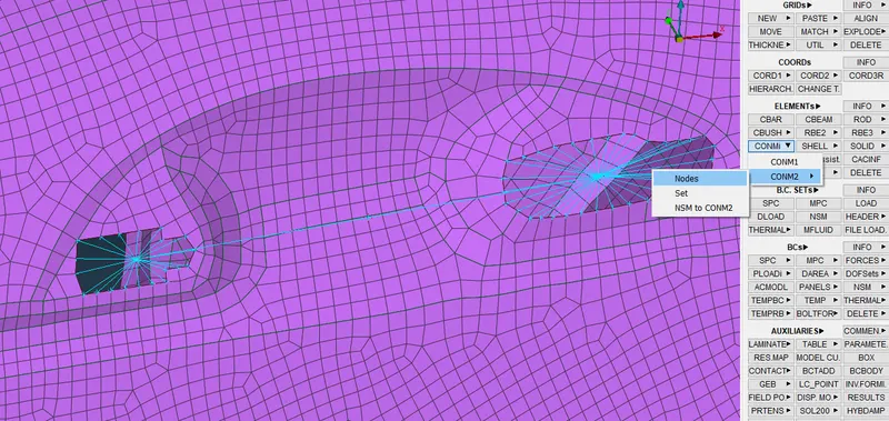
- We can apply the load using (NASTRAN module --> Elements --> CONMi)
- CONMi means, it is a definition of concentrated mass element coonection.
- Select on centre point & do middle click the connection created is shown in below image.
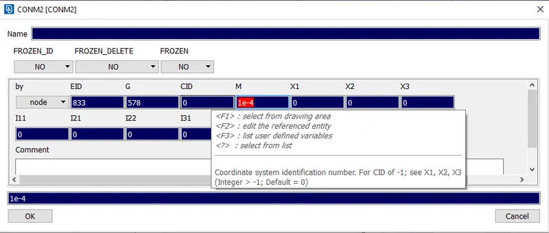
- Now, CONMi card will be open.
- Enter the Mass value. The entered Mass value should be in terms of Tons.
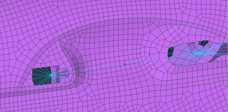
- In the above image we can see a 'Red Dot' which represents the Mass has been applied to the handle
WELD CONNECTIONS
- Seam weld connection.
- Spot weld connection.
#Seam weld
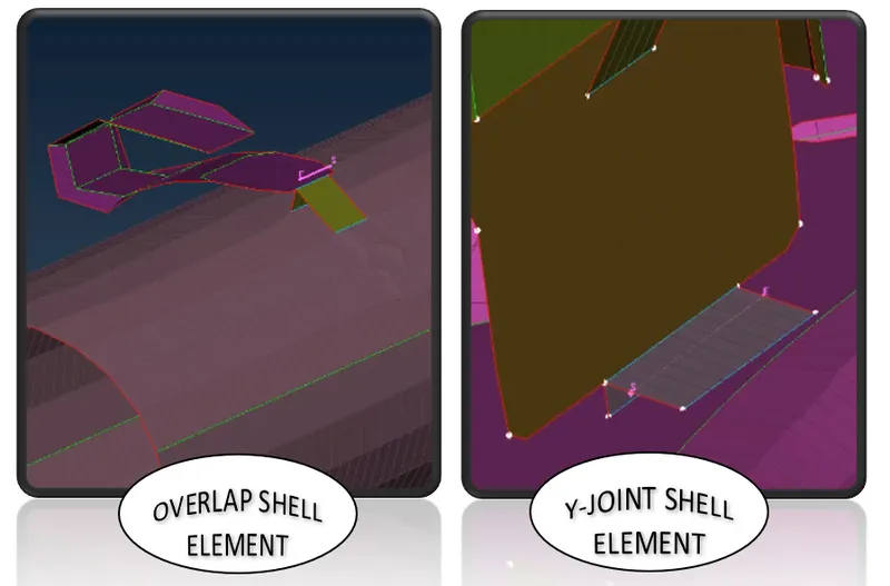
- Overlap shell element - To weld parallel sheet metal component.
- Y – joint shell element – To weld perpendicular sheet metal component.
#Spot weld
- RBE3 Hexa RBE3 element (Solid element)
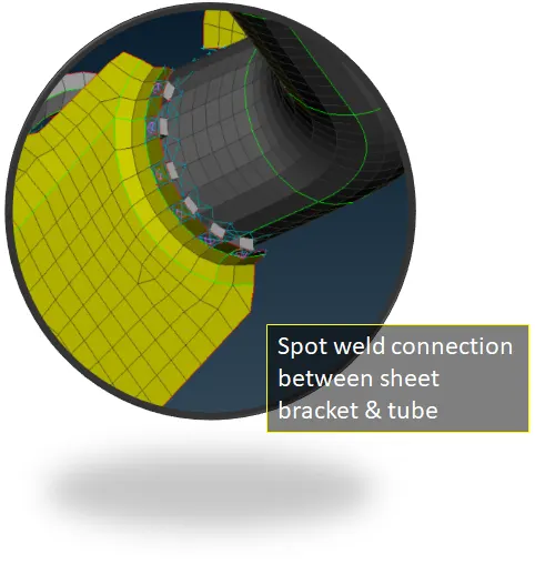
Steps to deploy Weld point connections
(Point creation for Spot weld)
- First we have to create a 3D Point using Topo Module --> Points --> On COG, select the area where we want to create a middle point by marking the area.
- Those square shaped points has created. It shows in the below image.
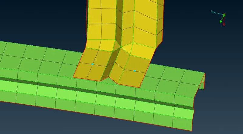
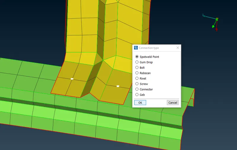
- In above image we can convert those 3D Points into Spot weld point using the option in 'Assembly tools' area, there we can see a option 3D points
- By selecting it we will see Connection type Pop-Up window, there we can select the Spot weld point option is show in below image.
- Finally the Points are converted into 'Spot weld' representation type, we can see it in above images.
(Bolt connection creation using Connection manager)
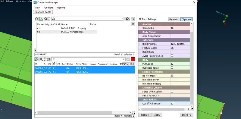
- Bolt created using the connection manager. 'FE Rep type for spot weld is RBE3 HEXA RBE3'
- We can see the status of Spot weld is indicate OK, which means our operation done.
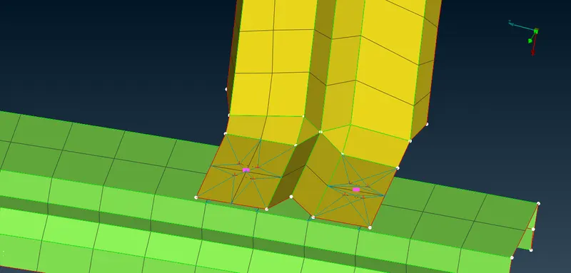
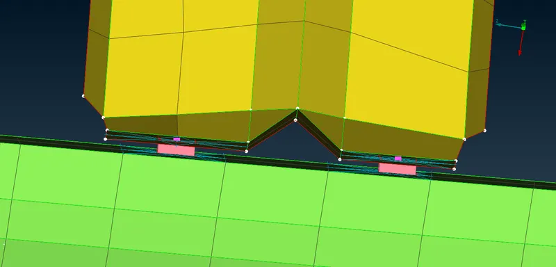
- In the above image we can see the spot weld point
- It is a Solid property created.
Steps to deploy Weld point connections
- The process for the Seam weld also as same as Spot weld creation.
- The only difference is here we use Curves instead of 3D Points
(Curve creation for seam weld)
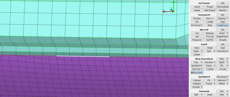
- Here we can creat a curve on the FE model using (Mesh module --> Perimeters --> Feat2Curve) option
(Converting the curves into Seam line)
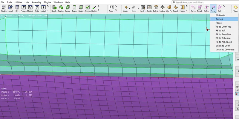
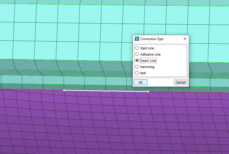
- In above image we can convert that Curve into seamline using the option in 'Assembly tools' area, there we can see a option called Curves
- By selecting it we will see Connection type Pop-Up window, there we can select the Seam Line option is show in above image.
- Finally the Curve is converted into 'Seam Line' representation type, we can see it in above images.
(Bolt connection creation using Connection manager)
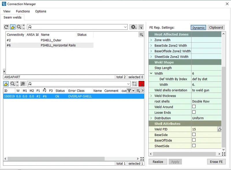
- Bolt created using the connection manager. 'FE Rep type for spot weld is Overlap Shell because the seam is created between the parralel surfaces
- We can see the status of Seam weld is indicates OK, which means our operation done.
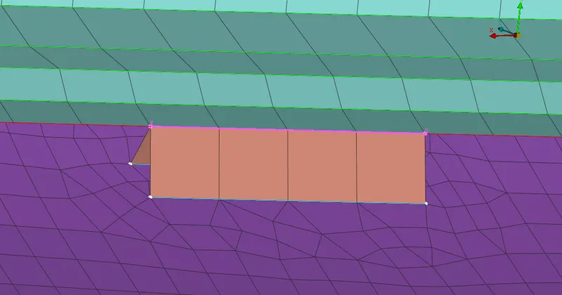
- Seam weld connection created, we can see it in the above image
C BUSH ELEMENT
- C Bush element is generally a spring element which will be having damping co-efficient or stifness value in three different direction.
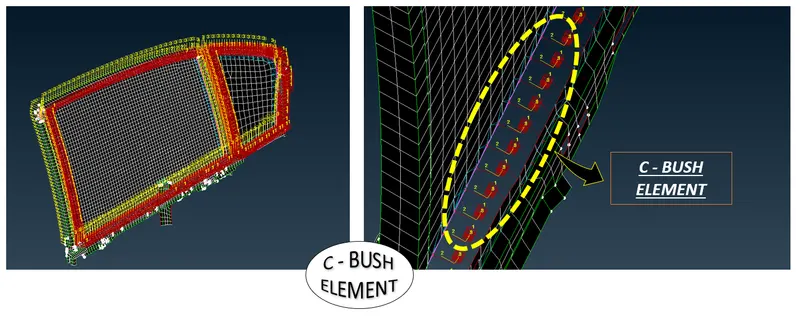
Steps to apply C - BUSH connections on Glass part of Door
(Connections for Weath Strips)
- First we have to create a Damping line
- Here we can creat a curve on the FE model using (Mesh module --> Perimeters --> Feat2Curve) option
(Converting the curves into Spot line)
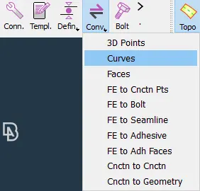
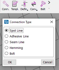
- In above image we can convert that Curve into seamline using the option in 'Assembly tools area --> Convert' option, there we can see a option called Curves
- By selecting it we will see Connection type Pop-Up window, there we can select the Spot Line option is shows in the above images.
- Finally the Points are converted into 'Spot Line' representation type.
- The other steps followed the same for other methods mentiond in previous connections using Connection Manager.
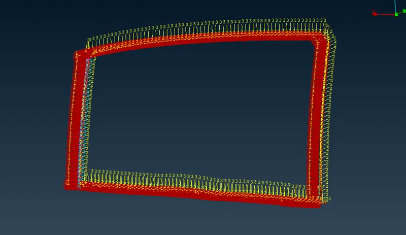
- We can see it in above image, CBushes are created successfully around the Window area
(Changing the Orientation of CBush)
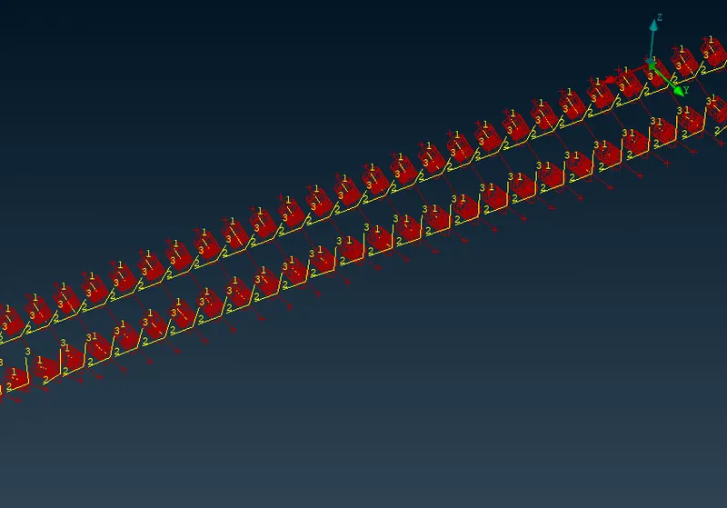
- Orientation of CBush is not the same for all the Bush connections so it may affect the simulation results.
- We can change with the Help of CBush Data base.
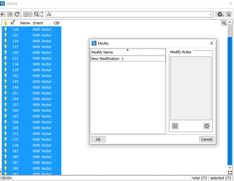
- Now modify the Orient from vector to Coordinate.
- This change is done to change the co ordinate from local axis to global model axis.
- Enter the CID value to 0.
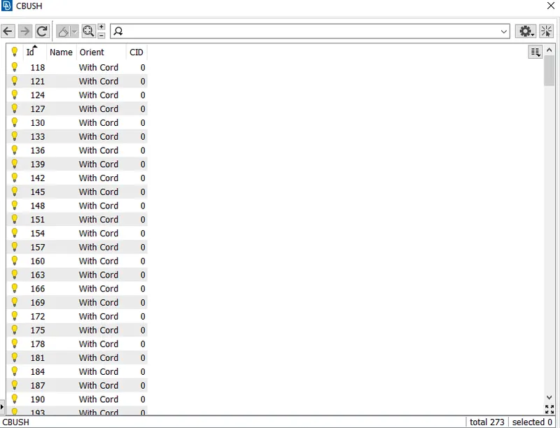
(Modified Orientation of C - Bushes)
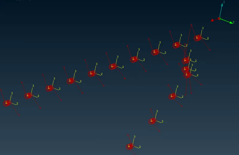
- Now we can see all the bushes are match with the Global Co-ordinate.
LEARNING OUTCOMES:
- In this challenge i learned about the different types of connections
- This challenge helps to explore the new options of NVH-NASTRON module.
CONCLUSION:
- Necessary connections for the given Rear door FE model has been deployed successfully.