Week 6 - Creating connection for Rear door
Week 6
Creating connections for rear door
Aim;
To apply different PIDs to different components and to perform connections for the given door model by using different techniques.
Procedure:
Import the given model into ANSA workspace. And the imported component is
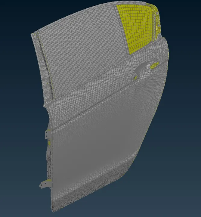
The given model is observed that the default PID is set for the whole model, now we have to create separate PID for different components.
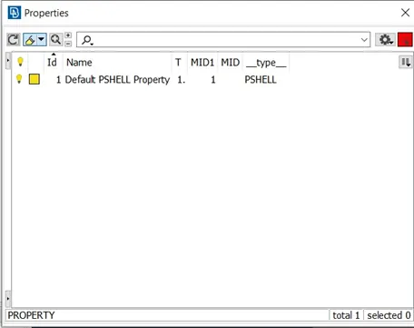
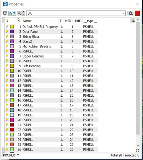
To create different PIDs, go to mesh module > macros > set PID and select different parts. The different PIDs created are
RBE2 connections:
To create RBE2 connection Nastran deck>elements>RBE2> many nodes. Select the nodes to create rigid connection and proceed to the next step and change part to ask always in the final step and click on finish the model browser tab will open and create a new connection part and drag it to the new group and rename the group.
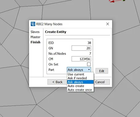
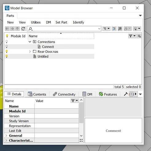
After that, when creating rigid connections, change the part option form ask always to current. And set the created connection part in the model browser as current.
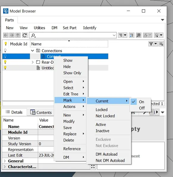
Two node RBE2 connection:
To create two node RBE2 connection, follow same as many nodes and select two nodes instead of many nodes.
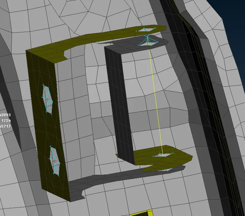
The above diagram shows two node connections. And in order to change the movement of the part change degree of freedom accordingly.
Bolt connection:
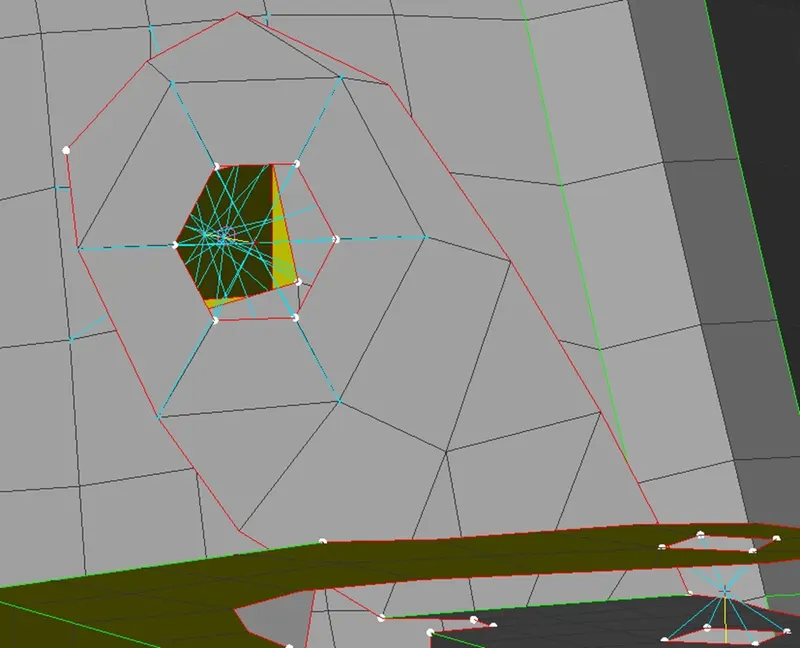
To create bolt connection, create 3D points from Topo Module> points> on the COG and select the edge needed and proceed to create 3D point. Now go to the convert option and select 3D point and select the created 3D point, then middle click and select bolt. Then go to connection manager and select the created bolt point and middle click. Now give the required inputs such as part 1,2 and even part 3 and select in/out in zones.
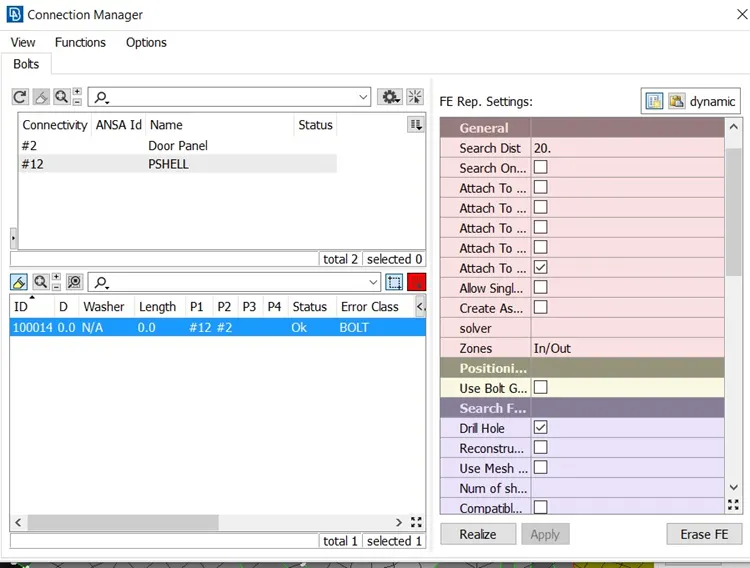
And then click on apply and realize thus the bolt connection will be executed.
C-Bush connections:
Here we use curves to create connection. Go to mesh module and under perimeters select “feat2curve”, which can be used to convert edges of the part to curve. Select the edges which have to be converted to curve and middle click.
Then under convert select curve and select the created curve and middle click, now go to connection manager and select the curve and middle click. Give the required inputs such as parts which have to be given as connection parts, search distance and PBUSH ID have to be entered, pbush id have to be created in property tab and that id have to be entered here.
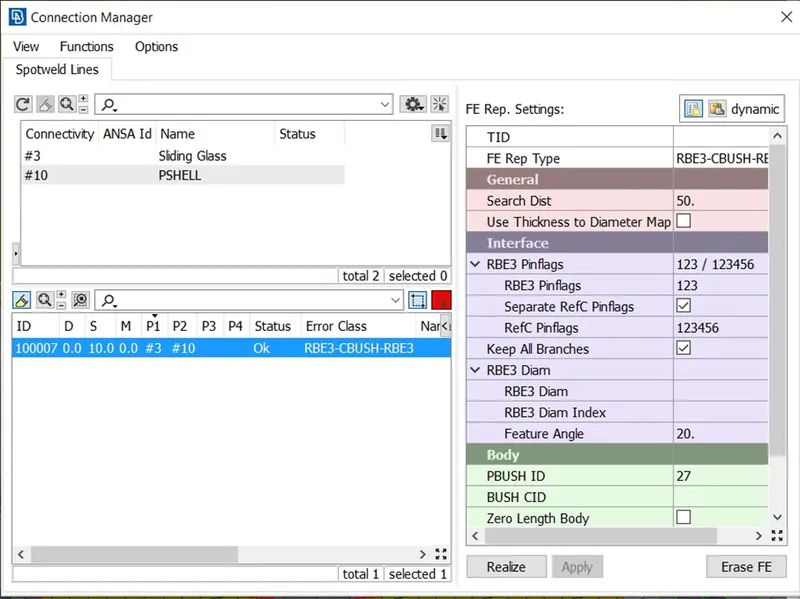
And then click on apply and click on realize
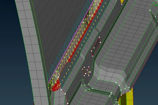
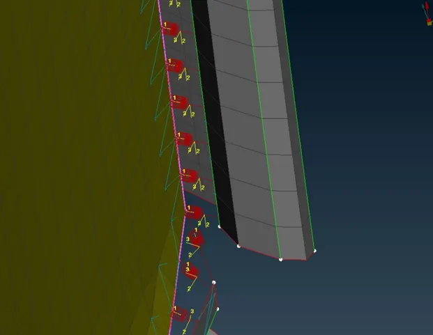
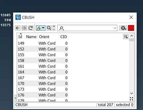
To align local coordinates which have been created in C-Bush connection to global coordinates, double click on CBUSH under Element and then click on “show/hide columns” and then search orient and CID, then check the respective boxes and select all property then right click modify. In new modification, select “with cord” under orient, and enter “0” under CID and then click ok. Now the local coordinates will be aligned with global coordinates.
Assigning mass:
In handle portion of the door, both bolting portions are enabled with RBE2 connection many nodes and then these two connections are connected with two node connection.
And then to add mass to the connection. Nastran deck>elements>CONMI>CONMI2, then select the nodes to assign mass then middle click then give mass in M column, and must be given in tones.
Learning Outcome:
Learnt to assign PID for various parts in the model.
Various connections such as Bolt, RBE2 many nodes and two nodes, CBUSH are learned. And to assign mass for the door handle is learned.
Conclusions:
PIDs are assigned to various parts for the given model. Various connections are created and realized.