Week 6 - Creating connection for Rear door
Aim
To perform the necessary connection for the FE model.
Procedure
step 1
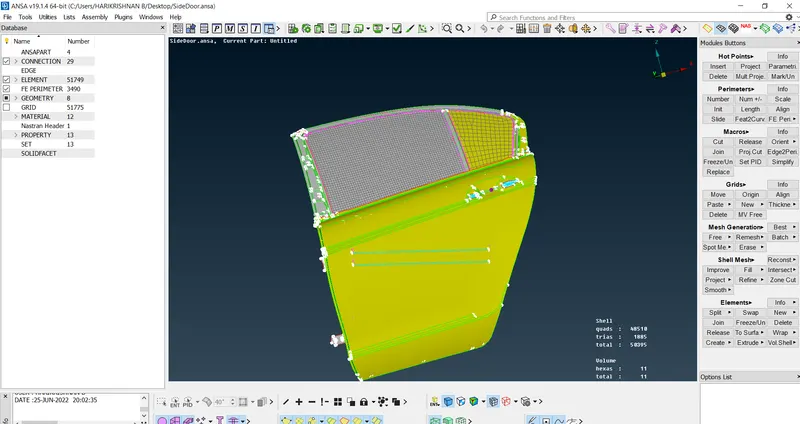
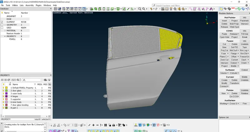
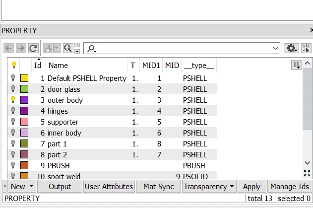
The model was in the same PID for FE, creation of PID was my first task, using the Set PID option created the necessary PID for the FE.
 |
 |
step 2
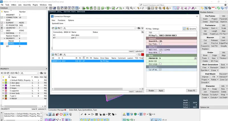
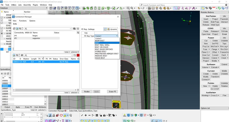
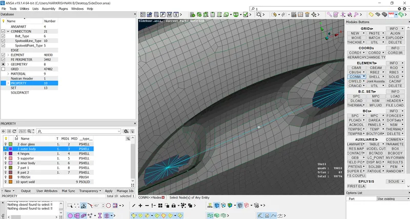
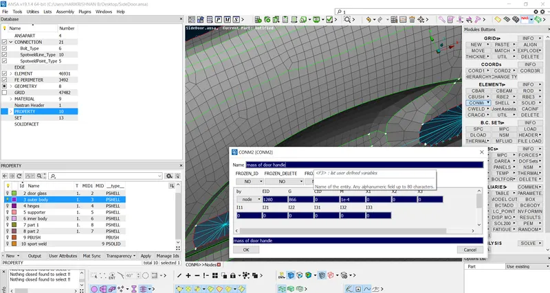
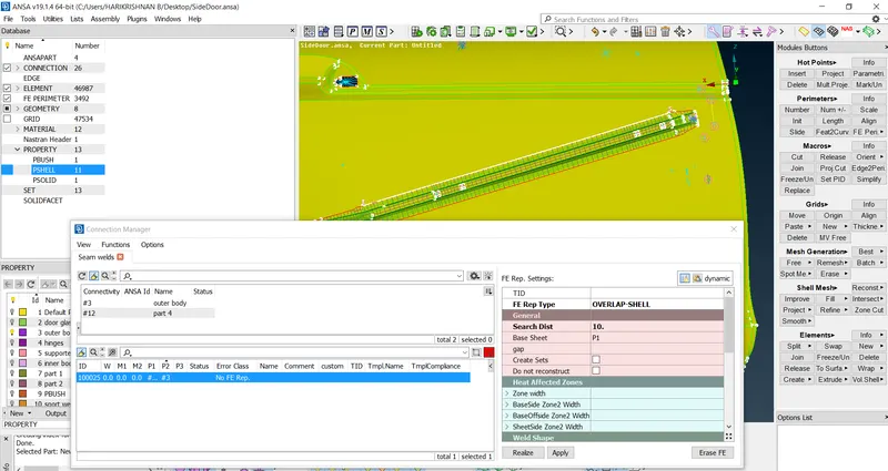
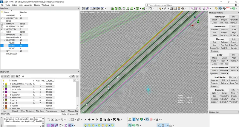
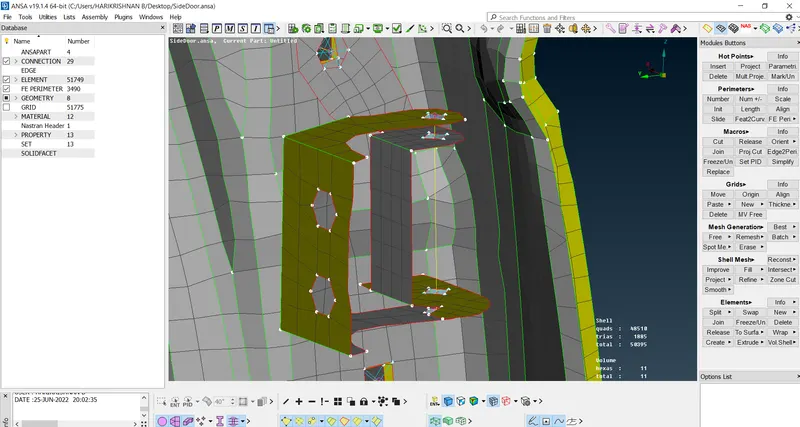
Understand the connections at the required point.First I did the c bush connection for the door glass by creating the curve for the glass outer part and bottom side of the glass curve copied and moving to both sides, followed by these steps: convert->curve->sportline. then connection manager->selected the curve-> space value->P1 and P2 selected-> RB3-CBUSH-RB3-> search distance provided the created the c bush 4 side of the glass.further created the bolt creating the COG point coveted into the bolt connection manager those required parts selected and connection carried out.a further hinge bolt created using RBE3 option and the degree of freedom to the z axis released to opening and closing the door. using the RBE3 tool the necessary connection between the part carried out, as it like the door handle using RB3 tool created the connection and the 100g mass value provided for the door handle using the tool COMN2 node tool.the necessary sport welding performed using the 3D point has been converted in sportweld point and using the RB3 HEXA. for seam weld curve creation and this curve converted in seam line and using connection manager for parallel type seam weld using over Shell and for perpendicular Y joint shell.
 |
 |
 |
 |
 |
 |
 |
Learning outcomes
Understood the types of connections like sportweld, seamweld, cbush, RBE and hinge.
Conclusion
The necessary connections done for the give model and understood what type of connection should perform for the location.