Week 6 - Creating connection for Rear door
REPORT
Aim: -
The main aim of this challenge is to create and apply properties from the given FE Model and to perform suitable connections.
Procedure: -
- The Side door model was imported/opened in ANSA.
- The first step after importing is to assign different PIDs to different components.
- This is done by Topology > Faces> Set PID> Select the comp>Middle mouse button>create new> PSHELL>Enter PID name> OK > Double mouse button to accept.
- Similar Steps are done to assign PIDs to other components as well.
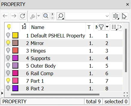
Assigning PID’s
- Now, since we don’t have any geometry, we need to create a curve from the feature. For this we choose the feature to curve option from the Mesh Module> Perimeter > Feat2Curve.
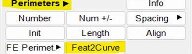
Feature to curve option
6. After this step we select the feature from which we want to generate the curve
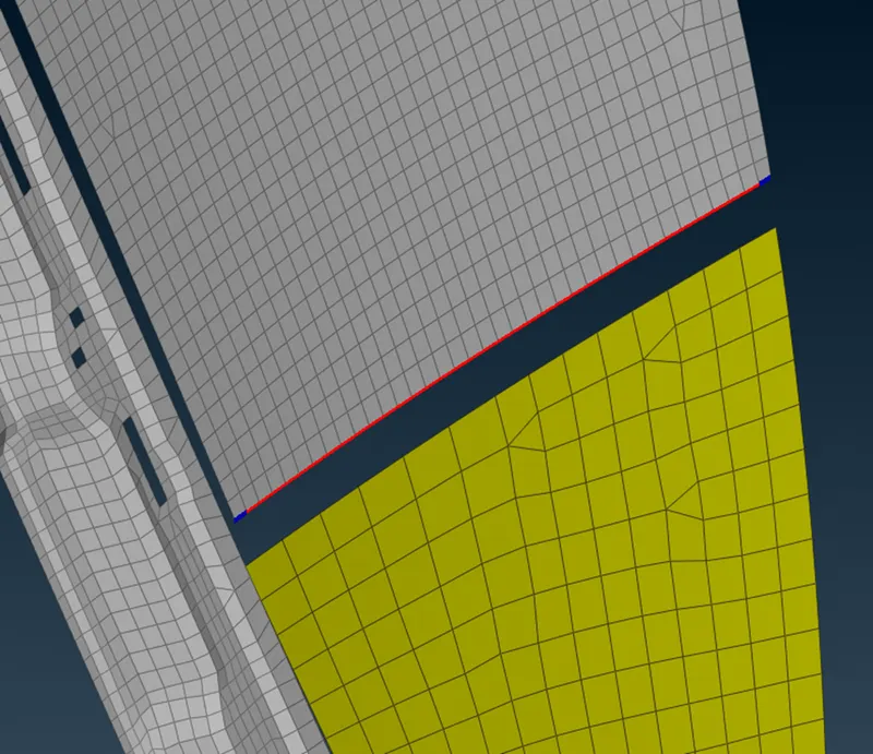
Feature line selection
- Once this feature line is selected, click the middle mouse button and assign the property. After this step since the Curve needs to be converted into a spot weld, we perform the following operation. Convert > Curves >Select the curve > middle mouse button > Spotline> OK.
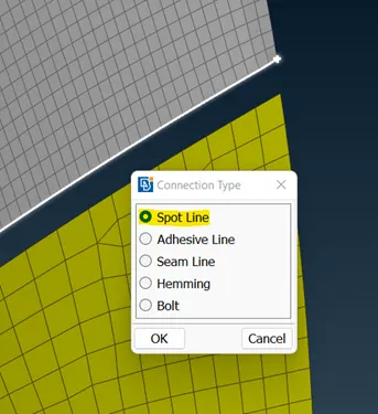
Converting Curve to Spotline
- Once this step is done, the curve is converted into a Spotline which will help us to connect the components in the future.
- Now, we click the spotline and then a middle mouse button which opens up the connection manager. When it opens up we set the spacing ‘S’ as 10 and P1 > right-click > modify > shift + F1 key > select the P1 >middle mouse > enter. Similarly, we set the spacing ‘S’ as 10 and P2 > right-click > modify > shift + F1 key > select the P2 >middle mouse > enter. Now, we see that the two properties have been assigned to P1 and P2.
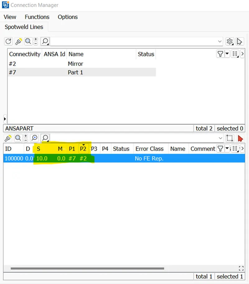
Selecting S, P1, and P2
- Now we set up the connection. In the “FE Type”, we enter RBE3 CBUSH RBE3, which means there is a bush element that is present between the two components. In the search distance, we type the value that the software will search for applying the connection entity.
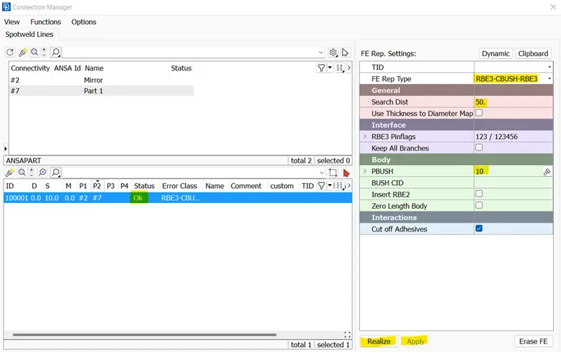
Connection Manager
In the PBUSH, we enter “shift +?” which opens up the property window for bush type. Over there we enter the translational (K1, K2, and K3) and rotational (K4, K5, and K6) stiffness values which need to be assigned, and click OK.
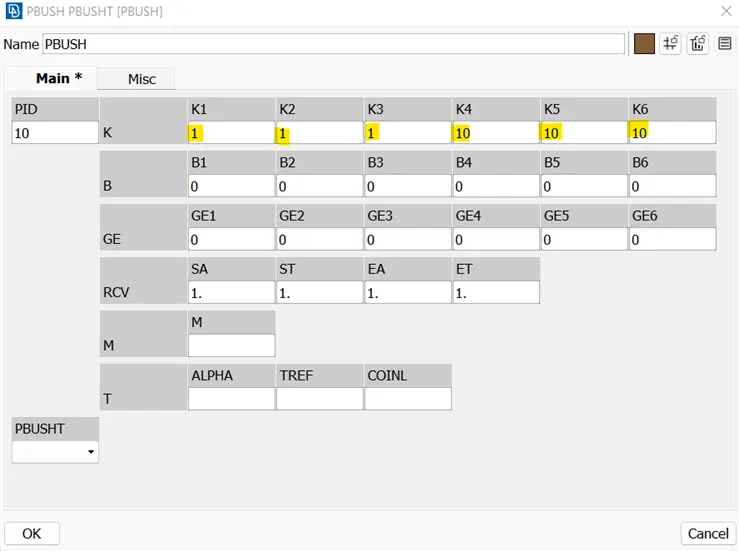
PBUSH Manager
- Then we Apply and Realize the connection and wait for the Status bar to show “OK”. It means that there is a connection established between the two components.
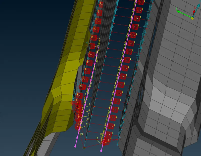
CBUSH Connection Realised
- Similar steps have been followed for all the CBUSH-type connections. CBUSH type connections have been used for the side door windows where usually the weather strip is applied.
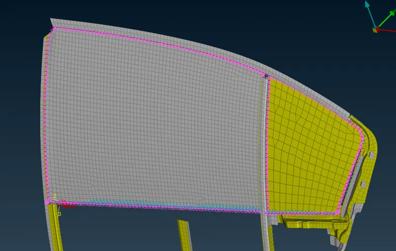
CBUSH Connection for windows
- Now, we establish the bolt connection between different components such as the supports, outer body, and the clips, for that we need to select a COG point between the hole which is done by Topology > Points > On COG, Switch on the “loop” option and select the boundaries of the hole. Then a middle mouse clicks to accept the COG point.
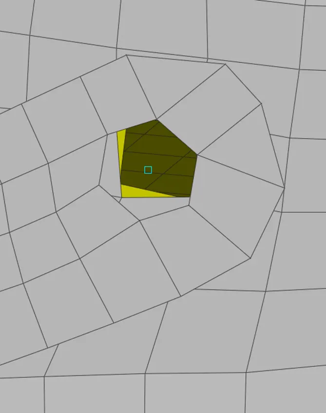
COG point
- Then we convert the COG point into a bolt connection. This is done by convert > 3D point > click on COG point > Middle mouse button > Bolt > OK.
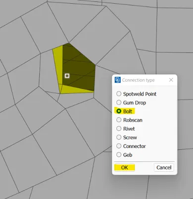
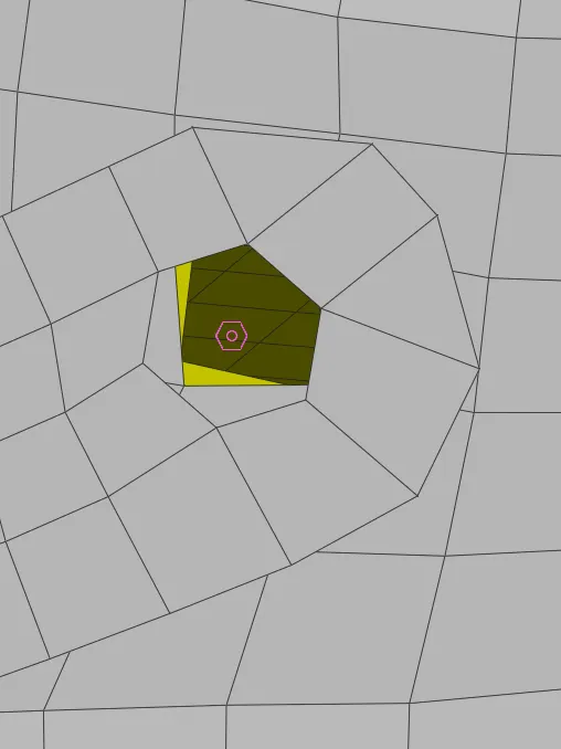
Converting COG to Bolt connector
- Now, once the bolt is made, we connect it to different components or PIDs. This is done by opening the connection manager. Inside the connection manager, we assign the P1, P2, and P3. P1 is the property for the first component. It is applied by right click in the P1 > Modify > shift+F1 key > select the component by PID > Middle mouse button > enter. Similar steps for P2 and P3 but with different components. In the “FE Rep Type,” we select BOLT and give the search distance. Then we click Apply and Realize. We wait for the status bar to change to “OK”. This ensures bolt connectivity between components. These are the steps to establish a bolt connection between components.
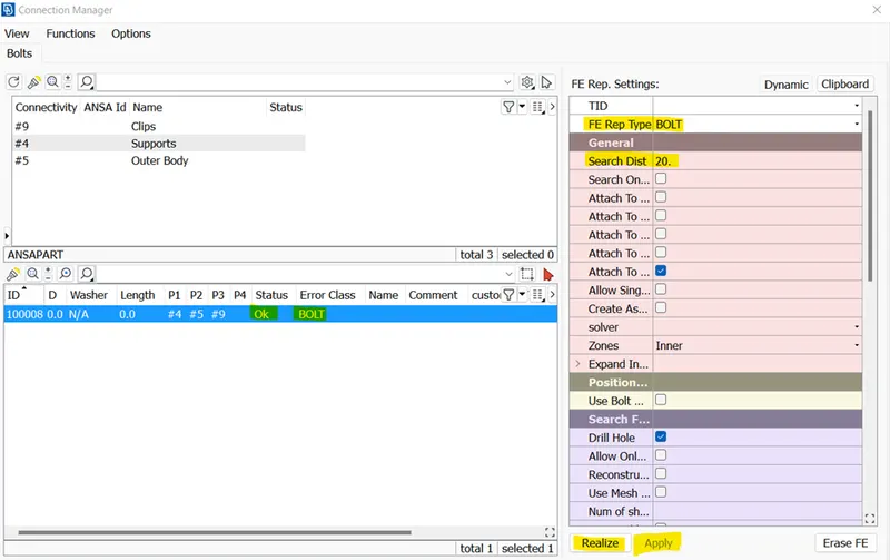
Bolt Connection Parameters
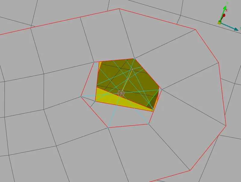
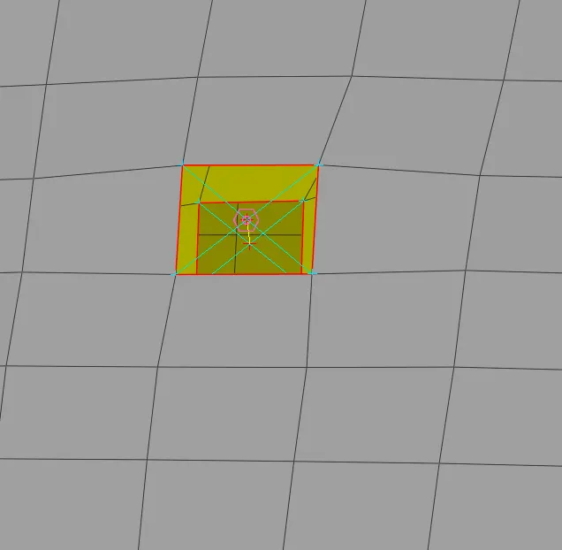
Bolt Connection
16. Similarly, bolt connections have been used when there are two holes parallel to each other.
17. All other holes which are present but not parallel to each other are mostly for weight reduction of the component or for passing the cables through them.
18. Now, we establish a hinge connection between components. This is created using the RBE2 link between them. With the already established bolt link. We go to Nastran deck > RBE2 > Two nodes > middle mouse click.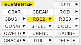
Now we set the part property.
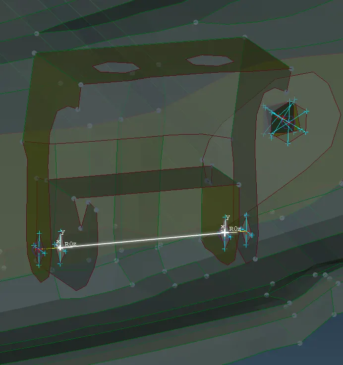
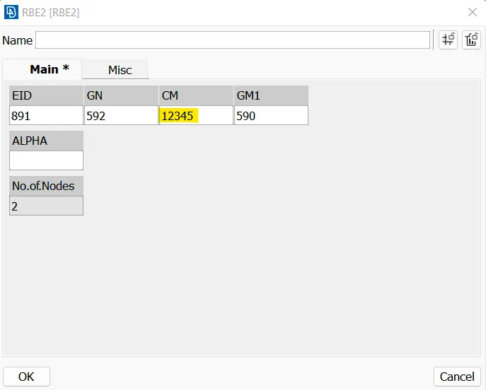
RBE2 Link for hinges Translational & Rotational constraints
Once it is set, we click the two nodes where we want the RBE2 link and set the translational and rotational constraints. While setting up the constraints, "6" has been removed from the "CM" ensuring that the z-axis for rotation is not constrained at all because the door would rotate along the z-axis.
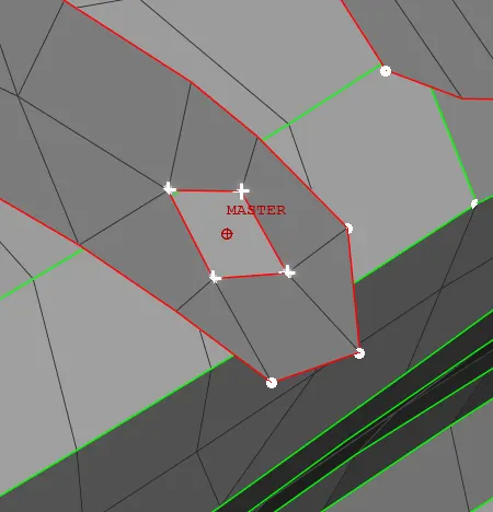
19. To make an RBE2 link from the spider, we go to elements > RBE2 > Many nodes > loop selection > select the nodes > middle mouse button to accept. The master node is selected which lies at the center. once we obtain two master nodes at both the points, we create an RBE2 link between them.
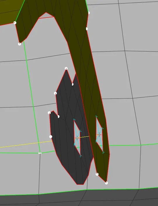
20. Now, we move on to establish a spotweld between the components. This is done by creating a 3D point where the spot weld would be. This is done by selecting the area. Points > on COG > entity selection > middle mouse click. After the 3D point is created, we convert it into a bolt, this is done by Convert > 3D point > select the point > middle mouse > spotweld point > OK.
21. Once it is created, we open the connection manager and enter the following details. P1 and P2 are the two properties whose components would get connected. We select it by "shift +F1 Key", "Fe Rep Type- RBE3-HEXA-RBE3", Search distance = 10 and for PSOLID we create a new property using "shift +?". PSOLID> OK. Then click apply and realize and wait for the status bar to change to "ok". Similar steps are done for other spot welds as well.
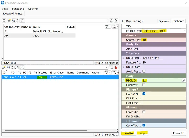
Connection Manager for Spotweld
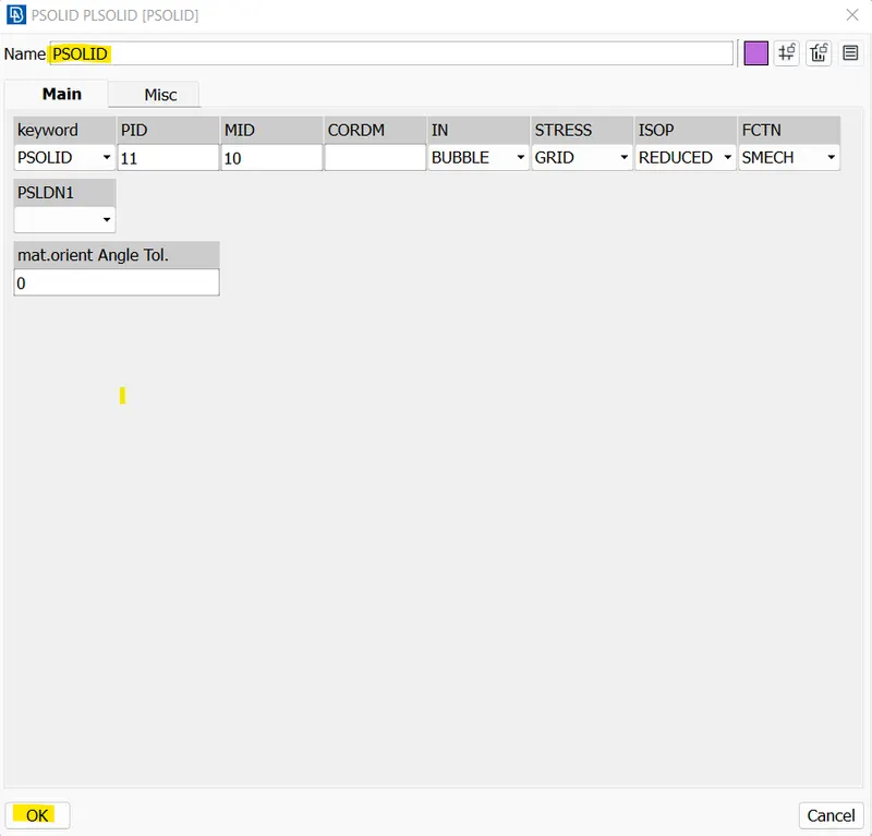
PSOLID Properties
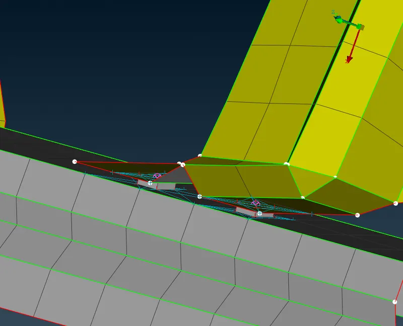
Spotweld Created
22. Now, we create seam weld between components. For this we choose the feature to curve option from the Mesh Module> Perimeter > Feat2Curve.
Feature to curve option
23. After this step, we select the feature from which we want to generate the curve. Once this feature line is selected, click the middle mouse button and assign the property. After this step since the Curve needs to be converted into a seamline, we perform the following operation. Convert > Curves >Select the curve > middle mouse button > Seamline> OK. 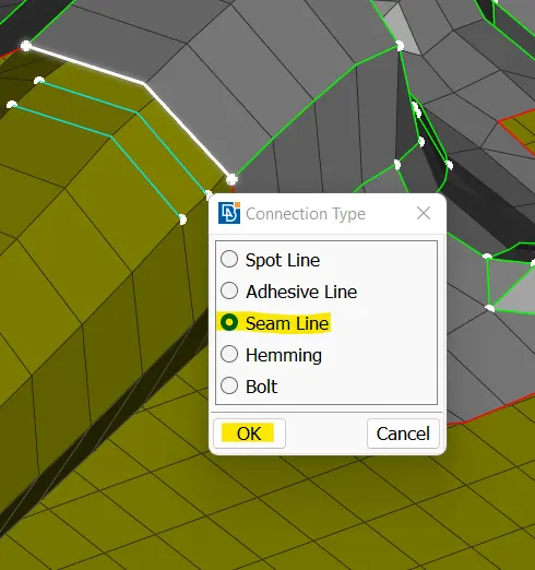
Conversion of Curve to Seam Line
24. Now, we click the seamline and then a middle mouse button which opens up the connection manager. When it opens up we set the spacing ‘S’ as 10 and P1 > right-click > modify > shift + F1 key > select the P1 >middle mouse > enter. Similarly, we set the spacing ‘S’ as 10 and P2 > right-click > modify > shift + F1 key > select the P2 >middle mouse > enter. Now, we see that the two properties have been assigned to P1 and P2. Now, we set the "FE Rep Type as OVERLAP-SHELL", Base sheet as Thickest, width as 5 which is the same as the target element length, and Weld property as PSHELL. We click Apply and realize and wait for the status bar to change "OK"
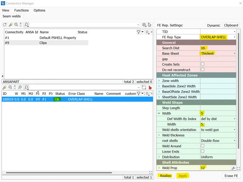
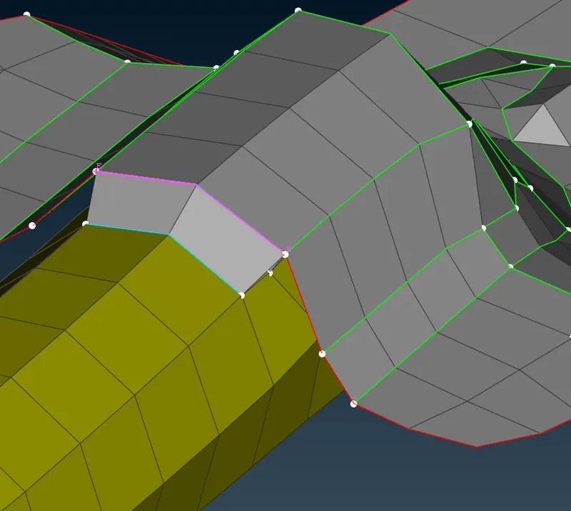
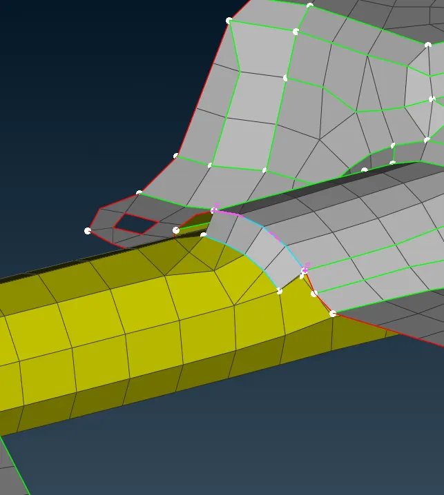
Applied and realized seam weld Connections
25. All the components are connected using connections and care has been taken that connections are made properly. Each connection has been shown and depicted in images.
Learning Outcomes:-
- Learned about the usage of feature to curve option
- Learned about conversion of 3D point to bolts or spotweld point
- Learned about different types of properties such as PSOLID and PSHELLS
- Learned about the FE Representation type
- Learned about applying and realizing the connections
- Learned about the different types of connectors
Conclusion:-
It can be concluded that connectors play an important role in maintaining the integrity of different components structurally.