Week 6 - Creating connection for Rear door
AIM:
For the given rear door FE model, create and apply different PIDs for different components and perform suitable connections.
OBJECTIVE:
To connect the different components in the rear door FE model with suitable connections.
PROCEDURE:
IMPORTING THE CAD MODEL:
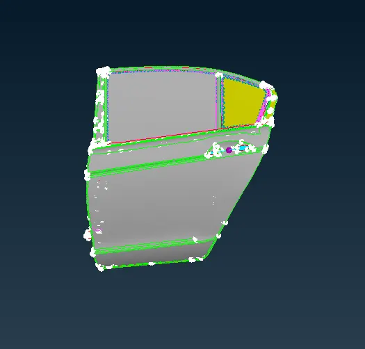
The CAD model is imported into the workspace by using file > open and select the CAD model.
The model will be imported into the workspace.
In ANSA we can import all types of CAD software file formats
PID CREATION:
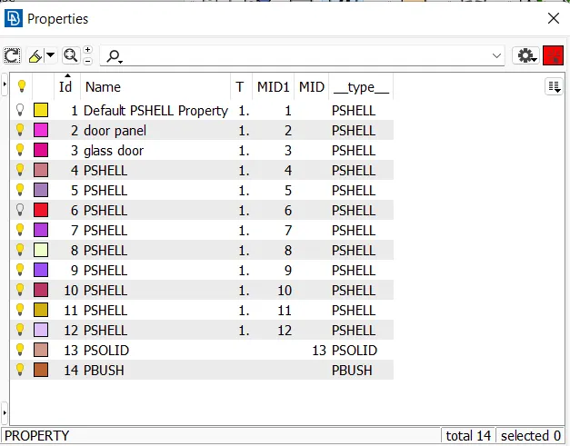
After importing model the model is with only one PID. so, the PID are splitted into different PIDS using topo > set PID and selecting
the parts by pid region option.
CONNECTIONS:
BOLT CONNECTION:
In this type of connection, we provide connections to wherever the bolts are going to be fitted in the rear door model. We first
create a 3D point near the holes of bolt connection using the COG option present in the points tab of the topo module.
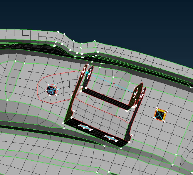
Then the 3D points are converted into bolt washer points using the convert option in the assembly tab
Then we go to the connection manager option present in assembly tab and select the point and then we middle mouse button
to get the connection manager tab.
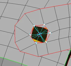
The parts are selected and the type is selected as bolt and then we provide the zones to be attached as inner. And then click on
realize option
SPOTWELD CONNECTION:
To create a spot weld connection go to topo > points > COG option and select edge to create a point.
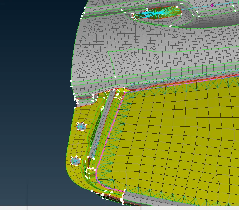
After creating the point, go to convert option and select a point and selct the spotweld point connection type
Then go to connection manager and select the spotweld point and click ok. connection manager will open
In the connection manager window the parts are selected to make connection and type is set to RBE3-HEXA-RBE3 and search
distance as 50.
CBUSH CONNECTION:
Go to mesh > perimeters > feat2curve option and select the edges and create a curve.
After creating a curve, go to convert > curves and select the curve and convert as spot line.
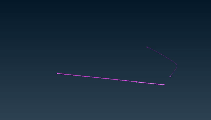
Go to connection option and select the spotweld point and click ok. Connection manager window will open.
In the connection manager window, select the part to make a connection and set it as RBE3-CBUSH-RBE3 and search distance
as 50 and select the keep all branches option.
In the connection manager window, create a PBUSH ID and assign the values for the propert
After setting all the setups click apply and realize.
After creating the CBUSH open the CBUSH window from the database and convert orient as with cord and CID as o for all CBUSH
The CBUSH is created along the global axis.
RBE2 CONNECTIONS:
The RBE2 connection is provided to the door handle by providing spider connections between two holes of the door handle. Then
the master nodes of the two spiders are connected to form a centroid. Then the con mass is provided on the COG point by using
CONMI > CONM2 in Nastran module.
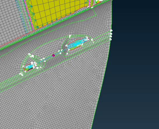
Then the mass is provided as 100gms in the CONM2 tab
Then the connections are made for the one holes that are present in the model to make it rigid.
To do that go to Nastran deck > elements > RBE2 > many nodes and select the nodes and create a RBE2 connection
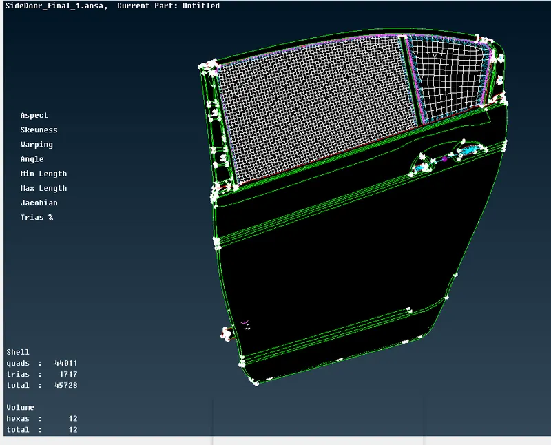
LEARNING OUTCOMES:
Learned how to create a bolt connection, spotweld connection, CBUSH connection and RBE2 connection.
Learned how to create and apply PID for different components.
CONCLUSION:
Hence the PIDS and the connections are made for the given side door model.