Week 6 - Creating connection for Rear door
AIM :-
To Perform Various Connections for the given FE Model in ANSA.
PROCEDURE:-
The Connections are carried out in different areas and by different methods. They are explained clearly below,
STEP -1 APPLYING CONMASS TO THE DOOR HANDLE AREA
Go to NASTRAN DECK > ELEMENTS > RBE2 > Select MANY NODES.
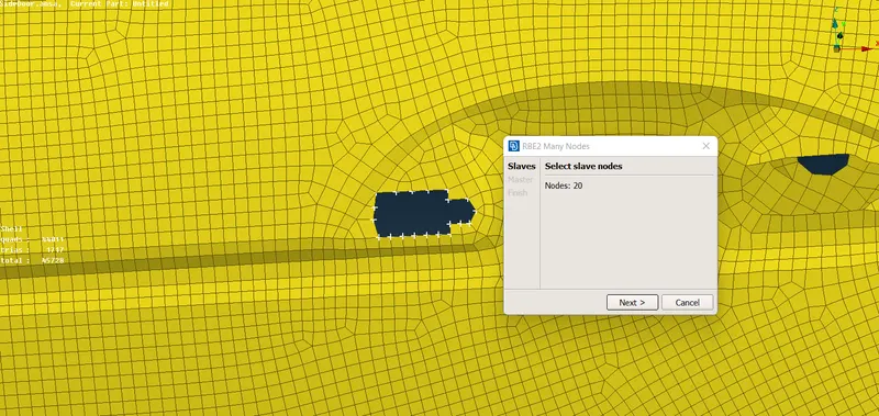
Fig -1 Selected Nodes are shown in the above figure.
After selecting the nodes give Next and give Ok to get them applied. This process should be done for both the handle areas.
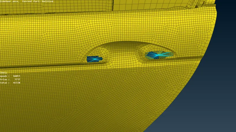
Fig -2 Nodes applied on both the areas.
Now go to ELEMENTS > CONMI > CONM1 and enter the mass value in M11. For this model the mass applied is 10.
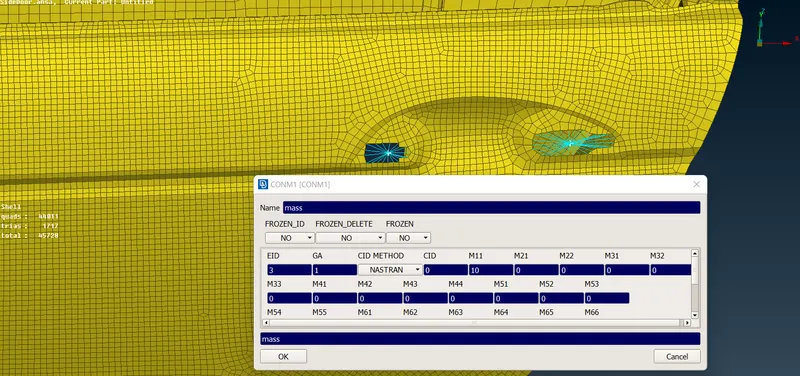
Fig -3 Conmass value entered.
After applying click on ok and the mass value will be applied.
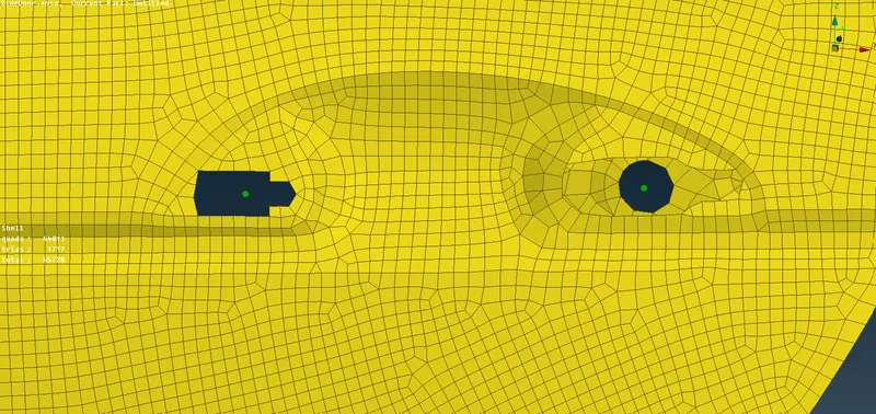
Fig -4 Applied Conmass seen in the above figure as green dots.
After appying mass we need to connect both the nodes. Select ELEMENTS > RBE2 > TWO NODES and select the Particular master nodes and give ok. The two nodes will be Connected to each other.
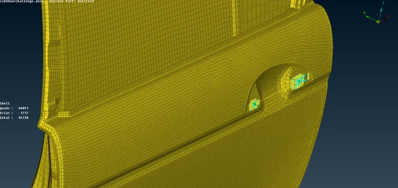
Fig -5 CONMASS for door completed successfully.
STEP -2 CREATING A BOLT CONNECTION
For creating a bolt we need to create a 3D Point. Go to MESH MODULE > ELEMENTS > COG > Select the middle surface and click ok. One COG Point will be applied which acts as a 3D point.
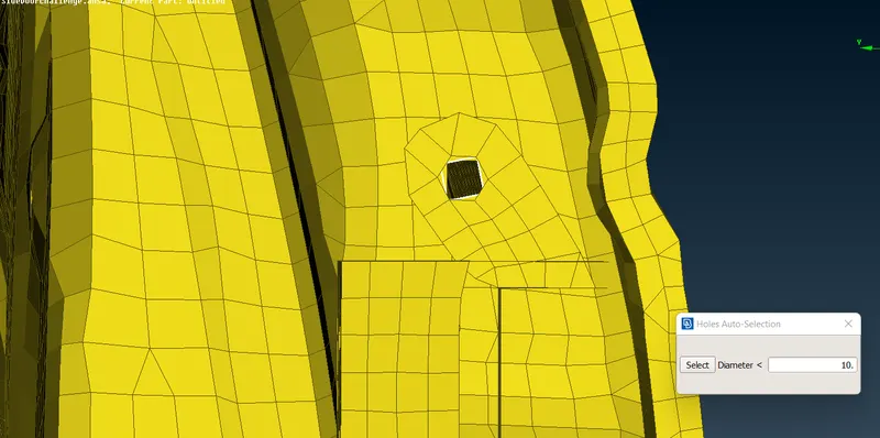
Fig -6 Selecting the surface for applying COG.
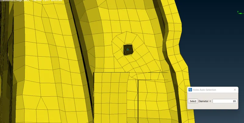
Fig -7 COG (3D) point is applied.
Now convert the 3D point to a bolt. Go to CONVERT > 3D POINTS > BOLT > apply ok and the point will be converted into a Bolt.
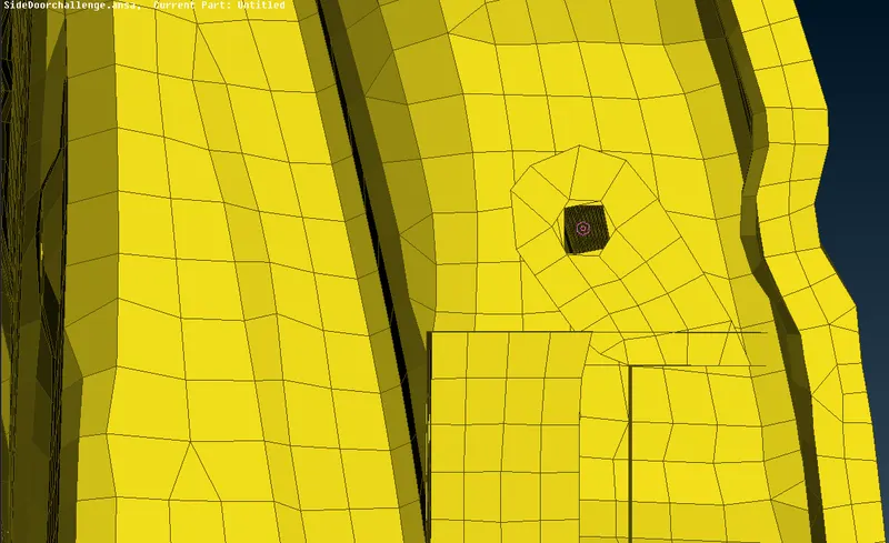
Fig -8 3D Point converted to a bolt connection.
Now go to connection manager and select the BOLT > MIDDLE CLICK and connection manager dialogue box appears and enter the Property 1,2 and 3 values respectively. 9 Since therevare 3 surfaces so 3 values to be entered).
Right click on the P1 and press FN+F1 in keyboard and select the first surface and middle mouse click. A #1 value will be shown. press enter from keyboard and the property will be added to connectivity. similarly add other values by following the same method by selecting the other two surfaces. you can verify if the properties applied or not by checking the #ID below P1,P2,P3.
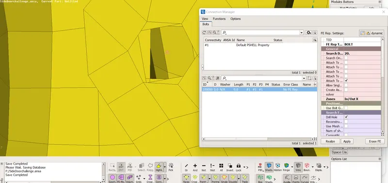
Fig -9 Property ID's are applied.
After applying properties , we need to go to FE REP. SETTINGS and select FE representn type as BOLT , Search distance -20 , Zones -IN/OUT and Apply and Realize. You can see the STATUS - OK and ERROR CLASS as - BOLT Which means the Bolt connection is completed.
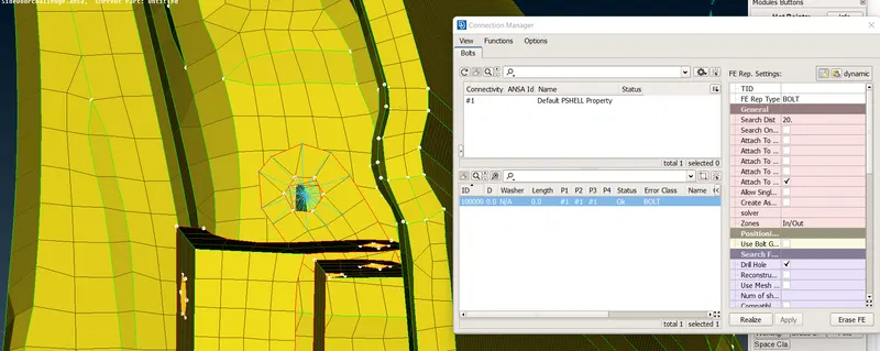
Fig -10 Bolt connection Completed successfully.
STEP -3 CREATE A SEAM WELD CONNECTION.
Similarly like bolt connection, we need to create curves for seam weld instead of 3D Point and bolt.
Go to MESH MODULE > PERIMETER > FEAT2CURVE option and select the required entity to apply the curve. After applying, the curve is generated which is transformed into a seam line by selection the option from the connection type dialog box.
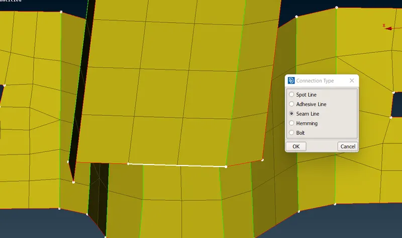
Fig -11 Creating Seam line
After creating the seam line, go to Connection manager and select the seam line and click on the middle mouse button. After clicking the seam line the model browser opens. Create a new PID as Seam weld.
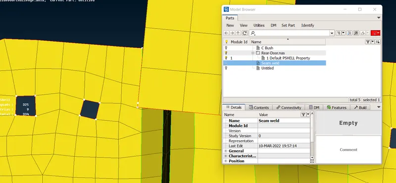
Fig -12 Seam weld property created.
Now enter the p1 and p2 values by following the same method as done in bolt connection and press the enter key for the apply of the values.
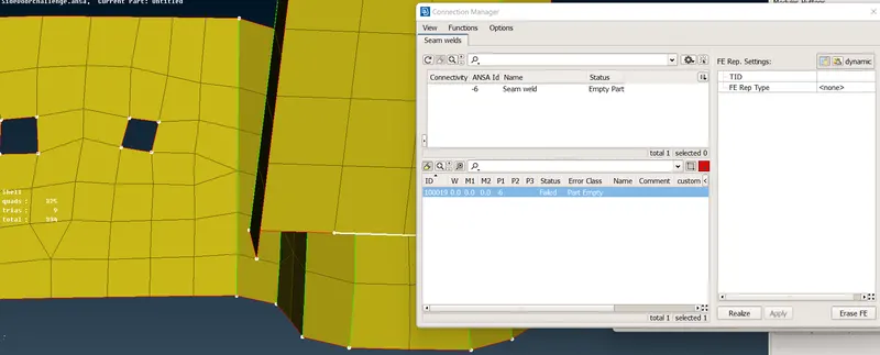
Fig -13 P1, P2 applied.
After applying Go to FE Representation and select the FE REP TYPE as -Overlap shell ( since its a parallel surface).
Search distance as -20
Base sheet - as Thickest
Select the Width and enter the width value. here the value is 3.
Root shells - Single or Double row.( as per requirement)
Weld pid - Select weld PID by clicking on SHIFT+? and select the weld pid( the one we created before).
After weld pid applied, click on APPLY and REALIZE.
Check on status and error class to verify whether assigned or not and its done.
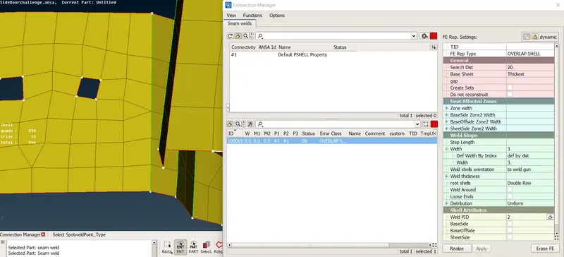
Fig - 14 Applying FE properties
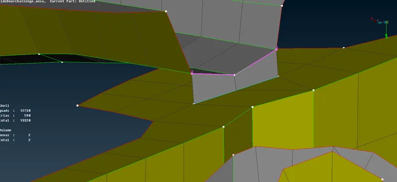
Fig -15 Seam welding successfully completed.
STEP- 4 CREATING A SPOT WELD CONNECTION
Similarly how the seam weld has been done same this is carried out in spot weld.
create a 3d point using the ELEMENTS >COG by selecting the entities.
Now convert the 3D point to spot weld point in the connection type dialogue box.
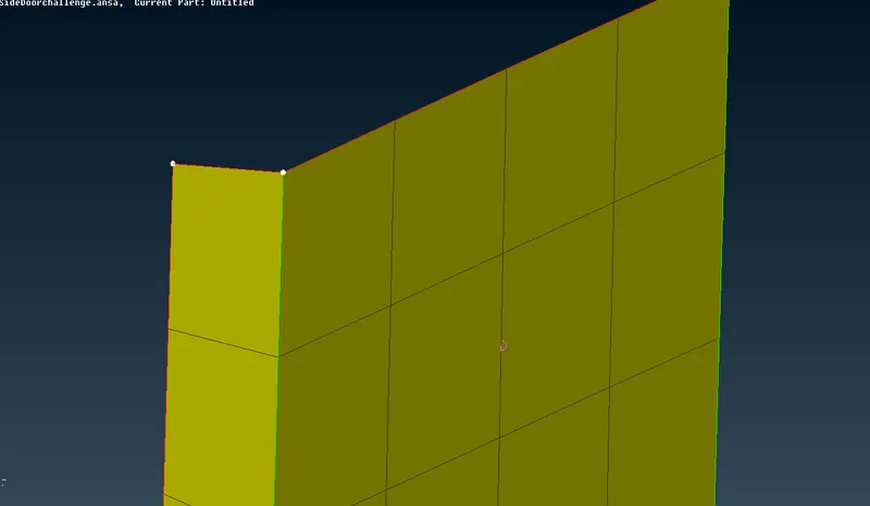
Fig-16 Spotweld point created
Now use the connection manager and select the spot weld point and Right click on the p1, p2 properties and fill them and give enter.
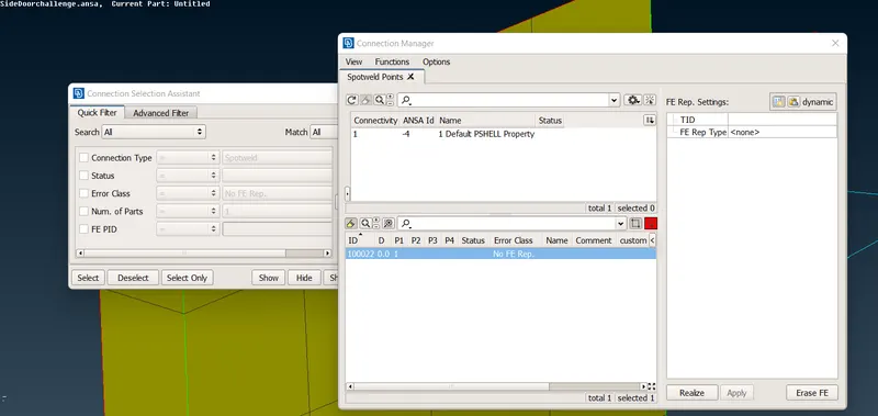
Fig -17 Property to be filled for spot weld.
Now after filling go to FE REPRESENTATION and select the required entities.
FE representation type - RBE3 - HEXA - RBE3
Search diatance - 20
Weld PID - Shift + ? key
And finally click on apply and realize.
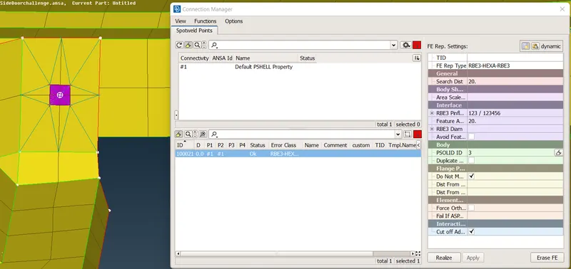
Fig -18 Applying the FE Representation properties.
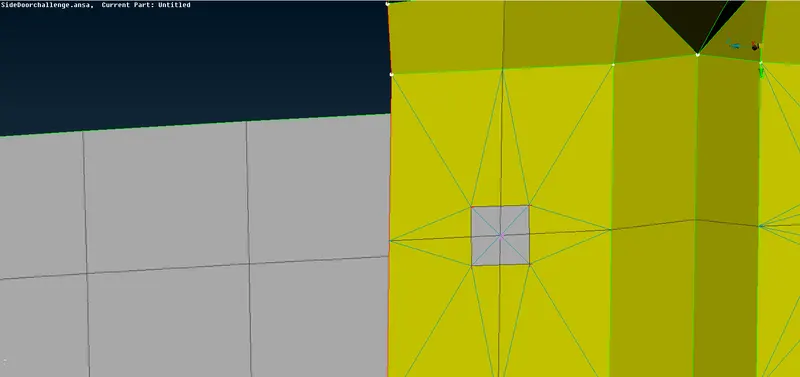
Fig -19 Spot welding completed successfully.
STEP-5 CREATING A CBUSH CONNECTION.
Go to Mesh module > perimeters > feat2 curve and select the entity to be transformed to curve.
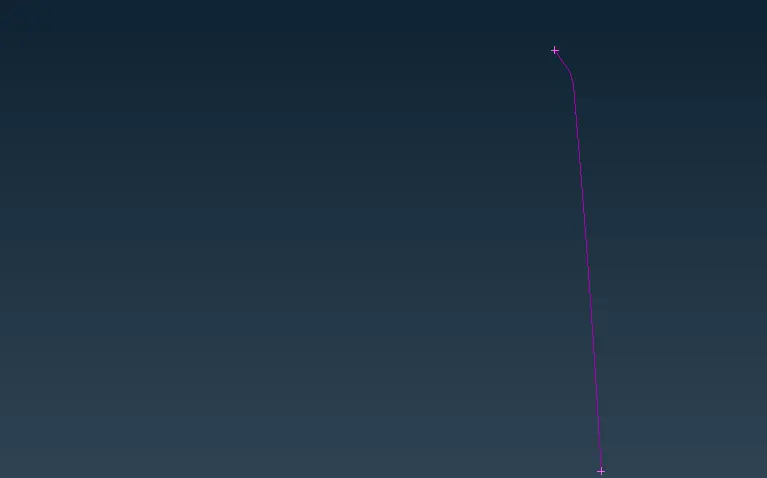
Fig -20 Checking for the curve by switching off the geometry.
Go to convert and select the curve and select the SPOTLINE from convert type dialog box.
The curve is now converted into a spotine.
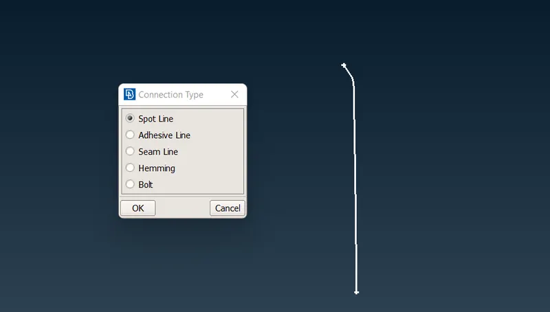
Fig -21 Curve converted to a spotline.
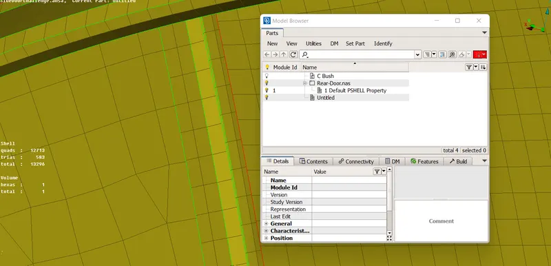
Fig -22 Creating New C bush ID after converting to spotline.
Go to connection manager and select the curve and click on middlle mouse click. In the dialog box we heed to add the P1, P2 properties as same we did it in the above connections. IN CBUSH we also need to Add SPACING VALUE. The spacing value used here is 10.
After applying all these the FE REPRESENTATION is carried out.
FE representation - RBE3 - CBUSH - RBE3.
Search distance - 20
P BUSH ID - SHIFT+?
After completing the fe representation,Go to properties and double click on the PBUSH ID and apply the values for Stiffness ( k1-k6 - as 10).
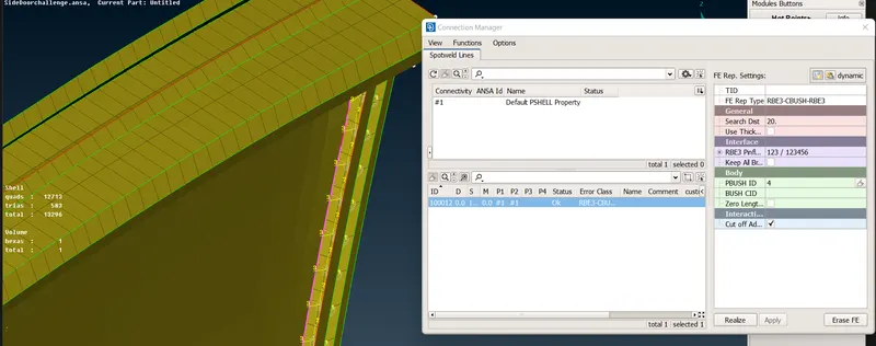
Fig - 23 CBUSH applied successfully.
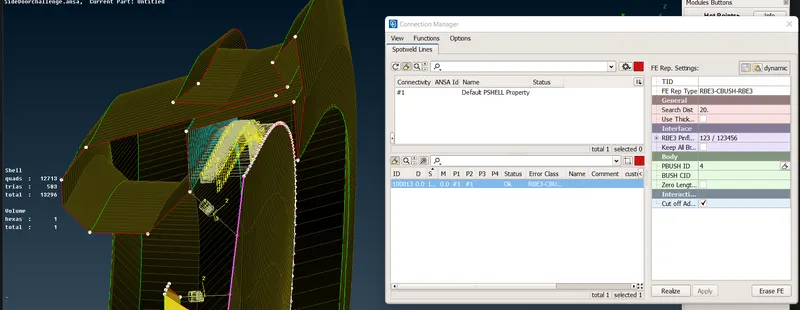
Fig -24 CBUSH elements for referrence.
CONCLUSION:-
The Connections for rear door model, different components are carried out by various methods successfully and a report has been created for better understanding of the process.