Week- 5 - Solid meshing
AIM :-
To Perform Volume meshing for the given Rear View Mirror Component.
Introduction :-
The following are the steps involved in the meshing of the given Mirror component.
Step 1 - Importing the Cad model into ANSA GUI.
The cad model is imported into ANSA from the downloads or from the saved folder.
After importing the model the first step is to change the resolution of the model to increase the Cons Resolution of the model.
This is done by Using MESH > PERIMETER > LENGTH > SELECT THE GEOMETRY and middle mouse click and enter the value as 1 in the average Length in the Length paramete dialogue box.
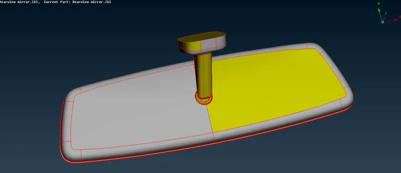
Fig -1 Model with Average length as 1.
STEP -2 Applying TOPO to the model.
The above model has no connectivity as you can clearly see there are double cons visible all over the model. To create connectivity the TOPO is applied on box selection of the model with a middle mouse click.
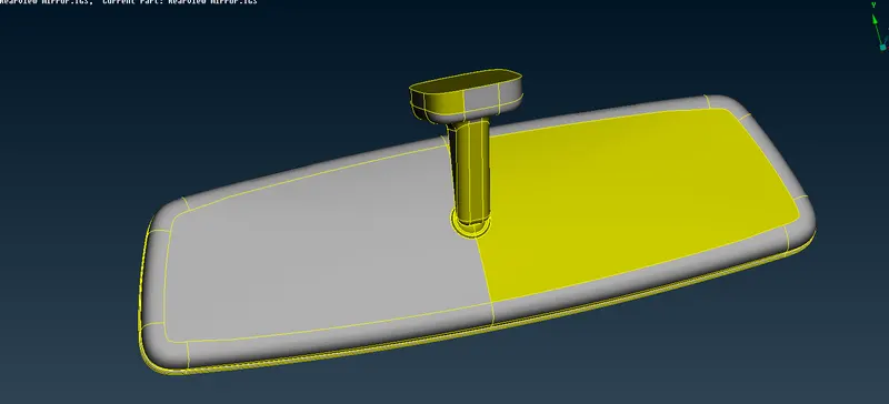
Fig -2 After applying TOPO.
Now the FACES > ORIENT > VISIBLE option from TOPO Module is applied to make the model in a single colour.
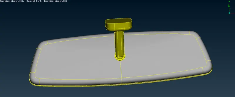
Fig -3 After applying the Faces Orient.
STEP - 3 Geometrical CHecking of errors.
There are Four Properties present in the mirror model, so each property is worked separately by checking the geometry, Clearing the errors followed by Quality criteria assignment, shell and volume meshing.
The first property is taken and checked for geometry. The geometry has thrown a Triple con error which you can see clearly in the below figure.
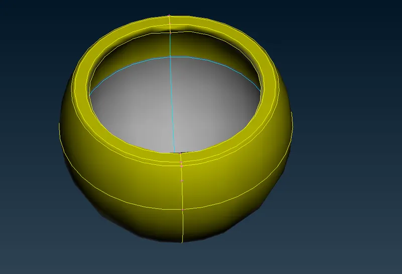
Fig - 4 First PID with Triple Con geometrical error.
Now the triple con is Released by applying CONS > RELEASE on the triple con present. After releasing the triple con the cons will be changed to red colour which indicates the release has been done. Now the FACES > TOPO is selected and the single cons are selected in a box selection with the double cons and topo is applied.
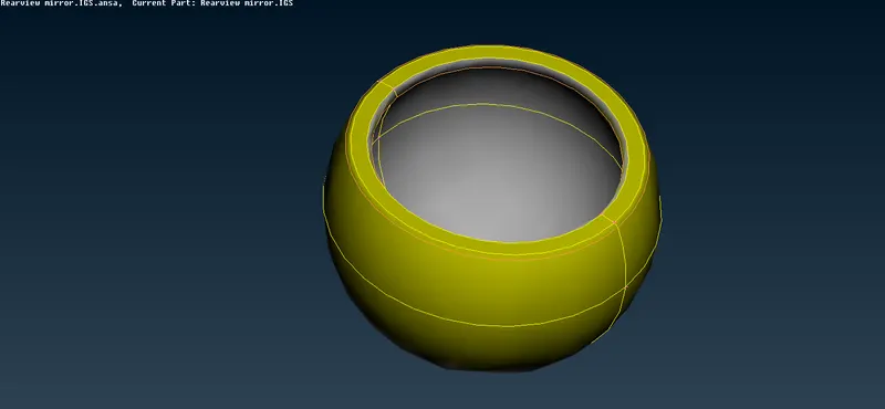
Fig - 5 After topo applied to single cons.
STEP - 4 Shell and Volume meshing of the PID'S.
Now the above part is to be Meshed. Before meshing the target element length is to be applied to the geometry. The Target element length as per the given quality criteria is 1. The target element length is applied to the CAD Model.
The QUALITY CRITERIA parameters are also to be entered. The values are ,
MINIMUM LENGTH - 0.5
MAXIMUM LENGTH - 2
Now the meshing has to be carried out. For meshing in the Mesh Module under MESH GENERATION > BEST option is used.
The model is to be first meshed with shell elements and then followed by solid meshing. The model has to be analysed for Flat surfaces and curved surfaces before meshing. The FLAT surfaces are to be Meshed with NORMAL TRIA elements whereas the CURVED FACES are to be meshed with ORTHO TRIA elements. This is avery important thing while meshing.
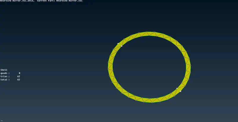
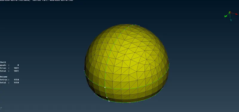
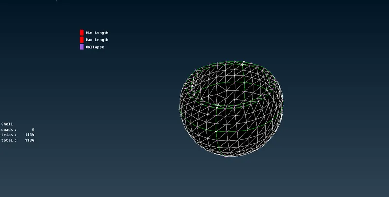
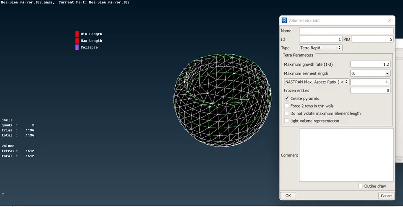
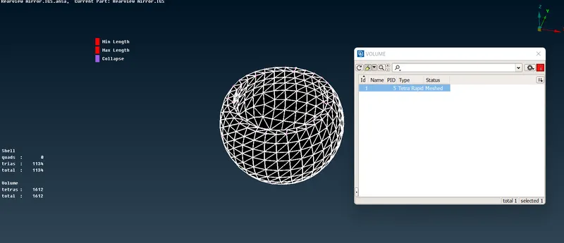
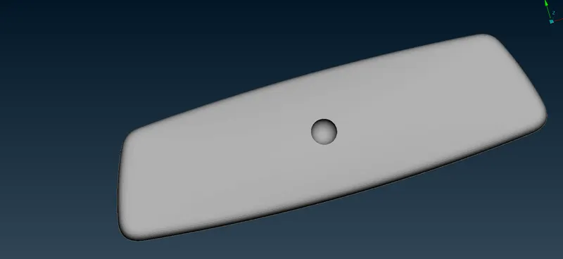
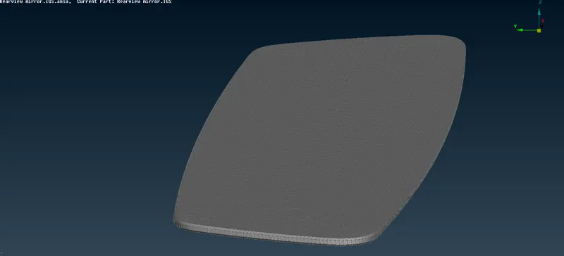
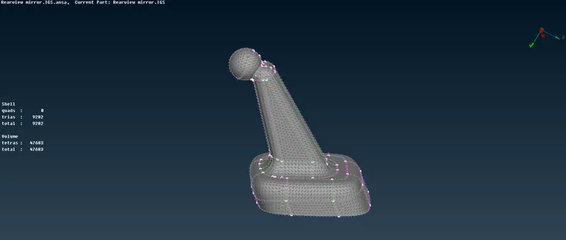
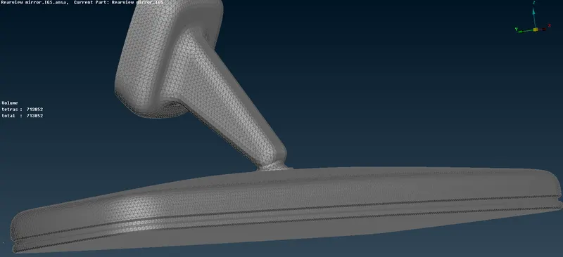
- Learnt of doing solid meshing on Flat and curved surfaces with Normal Tria and Ortho Tria elements.
- Learnt to do volume meshing by defining the shell mesh.
- Learnt to clear the off elements and about fix quality tool.