Week 3 - 2D meshing for sheet metal
AIM:-
To perform 2-D Meshing on the Hood model using ANSA.
OBJECTIVE:-
To perform the Geometrical clean up on the Hood model followed by shell meshing using the given element quality criteria. After meshing the component, thickness has to be assigned.
|
S.No |
Quality Criteria |
Value |
|
1 |
Target/Average length |
5 |
|
2 |
Minimum length |
2 |
|
3 |
Maximum Length |
7 |
|
4 |
Aspect |
3 |
|
5 |
Warpage |
15 |
|
6 |
Skewness |
45 |
|
7 |
Jacobian |
0.7 |
|
8 |
Minimum quad Angle |
45 |
|
9 |
Maximum quad Angle |
135 |
|
10 |
Minimum Tria Angle |
30 |
|
11 |
Maximum Tria Angle |
120 |
|
12 |
Tria Percentage |
15 |
INTRODUCTION:-
A Car Hood also referred to as a bonnet is a cover that rests over the Engine of a Front- Engine vehicle. Its purpose is to provide access to the engine compartment area for Repair and maintenance. The Hood is opened by Pulling the interior latch present beneath the Dashboard of Driver side. when it is pressed the hood will shift and raise slightly, and can then be opened fully with the exterior Latch. Stay Rod is available with most of the cars to hold the bonnet in open condition.
METHODOLOGY:-
- Import the model into ANSA GUI
- Checking for Geometrical Errors
- To Extraxt the Mid surface
- Assigning separate PID's to each feature.
- Topology clean up and assigning the quality criteria.
- Perform meshing using quad and tria elements.
PROCEDURE:-
Step-1- Import the model into ANSA GUI:-
The CAD Model of the hood is imported into the ANSA Interface.
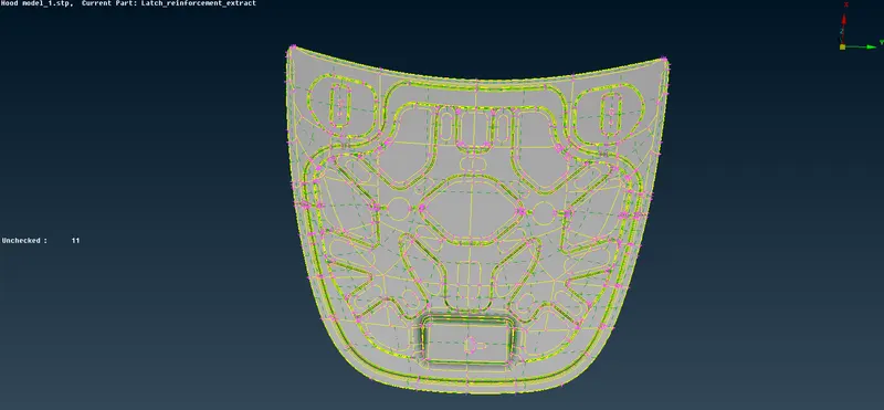
Fig 1-Hood Model for preprocessing is imported into ANSA.
The resolution of the model needs to be changed in order make it finer to see the original shapes.
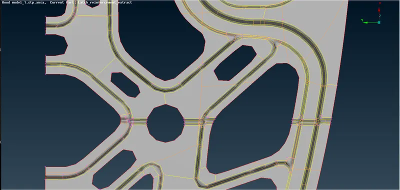
Fig 2- As you can see the features are not visually good due to low resolution.
The Resolution of the model can be changed by using the,
Mesh > Perimeter> Length > 1
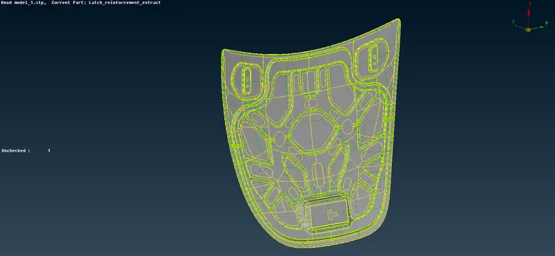
Fig 3 - Resolution changed in the model.
Step 2- Checking up for any Geometrical errors:-
Generally CAD Data is to be imported in .step, .iges, .stp formats.
Geometry clean up involves in cleaning up of geometrical errors that pop up during the check. The errors can be cleared by manually or by using the Autofix Option present in the checks manager > Geometry dialog box.
The errors can be checked in,
Checks manager > Geometry.
Before executing the geometry check, it is necessary to turn on the Triple cons and Single cons to ensure surface overlapping and for closed geometry.
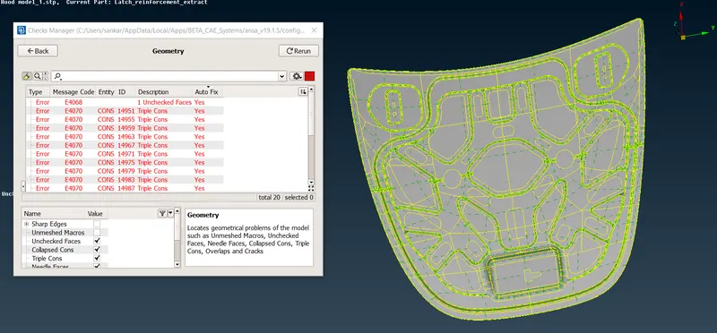
Fig 4 - Geometry errors that are present in the hood model.
The unchecked faces error is cleared using autofix option, whereas in case of Triple cons it is cleared manually.
The triple cons are formed due to very less distance between two regions. The triple cons should be cleared in order to fix the errors.
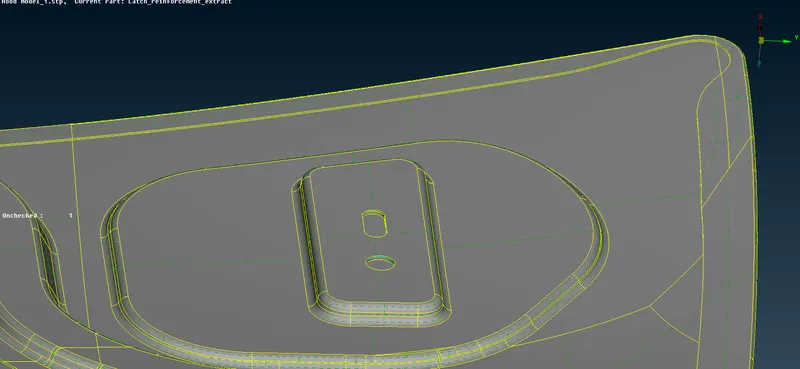
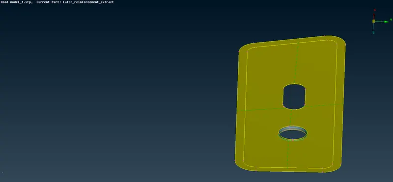
Fig 5- You can see the Triple cons present in the Hinge area of the hood.
The triple cons are cleared by using Cons > Release > Topo (Box selection of single cons with respective adjacent sides).
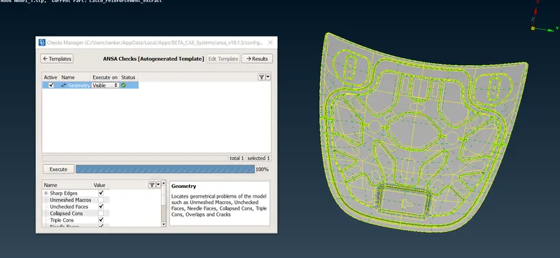
Fig 6 - The geometry clean up is done now.
Step 3 -Extracting the mid surface :-
Measuring the Geometry :-
The model has to be analysed before extracting Mid surface. Measurement of the CAD is taken in required areas to decide the way of extracting the Mid surface.
Measurement is carried by Utilities > Measurement
The Measured value of each region is used to assign thickness to the mid surface.
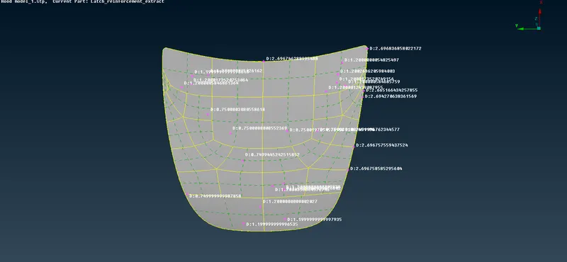
Fig 7 - Geometry Measurement taken.
After analyzing the model, the Mid surface extraction is to be done by using offset/ Feature angle command since each part in the CAD are with separate and respective uniform thickness.
Faces > offset > Faces
In the Feature angle option the outer body of the panel is selected ( Zoom in and select by clicking the cross hatch) and enter the offset value.
The thickness of Hood inner panel is 0.75mm, so the offset value has to be 0.375mm. Always notice the direction of the arrow which indicates the mid that will be created from the parent.
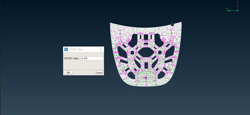
Fig 8 - Offsetting the Inner hood panel.
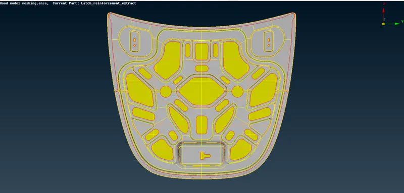
Fig 9 - Final mid surface of the Hood Assembly.
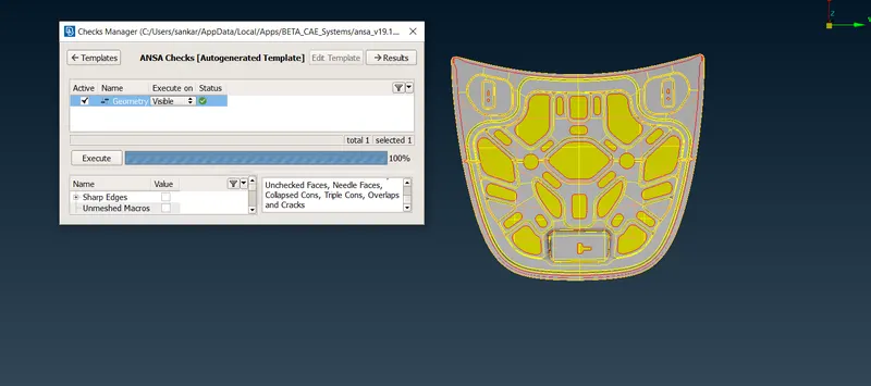
Fig 10 - Checking for geometry for any errors. No errors available.
Step 4- Assigning separate PID to every feature.
PID represents to Property ID. Assigning a PID to a feature has many associative entities like Thickness, Density, Poisson's Ratio, Young's modulus within it. When a component has a uniform thickness throughout its ok to have one property ID for the mid surface, whereas in cse of varying thickness over its surface, it is necessary to assign separate Part ID's to every region.
While Assigning PID each region will have its own thickness with respect to its parent geometry. We will assign separate colour for each region for better visual understanding.
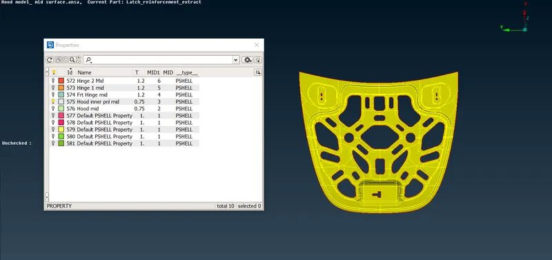
Fig 11- Separate Part ID for each Mid surfaces is created and thickness assigned.
STEP 5 - Topology Clean Up and Assigning the quality criteria:
The topology clean up includes Cleaning up of any unwanted hot points present in the surface of the component and also measurement taken to avoid issues like minimum length failure criteria of elements followed by defeaturing the area.
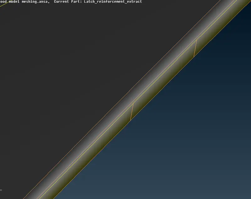
Fig 12 - Edge of the hood outer panel with Top and Bottom cons suppressed (defeaturing) to avoid min length failure.
After topology and defeaturing, the stated Quality criteria parameters are to be assigned and surface meshing to be performed.
The quality criteria are followed before performing the mesh in the model.
Minimum and Maximum Length:
Minimum Length -2mm
Maximum Length -7mm
This element length criteria is to define the distance between two nodes over surface. If any two nodes having a distance less than 2mm and greater than 7mm will fail in element size.
Average length is set as - 5mm ( as per parameter requirement).
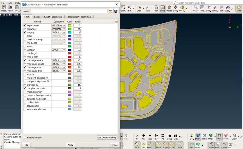
Fig 13 - Quality Criteria
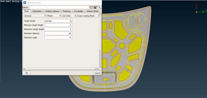
Fig 14 - Mesh Parameters
STEP 6 - Perform Meshing using Quad and Tria elements:-
While performing meshing we should keep in mind that no rotating quads and opposite tria elements present near each other and to ensure proper Mesh flow.
Before Performing mesh, make sure to define the length of the perimeter and macros as 5. This is to ensure that adjacent nodes have a distance of 5mm between them.
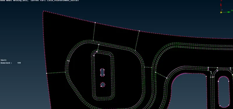
Fig 15 - Average length of 5mm ( Distance between two nodes).
Now switch to Hidden mode then proceed with the Mesh Generation. The mesh generation is done by two methods here,
- Best
- Spot mesh
Rectifying Errors in the mesh generated:
Minimum and maximum length error: These errors arise when an element does set into defined value. To rectify use split option and add cons if required.
Rotating quads: To rectify this use split and split the quad into tria and swap trias to avoid opposite facing of them.
Opposite Tria: Opposite trias can be eliminated by using split option and also by using paste option to join them as one.
The tools that are mostly used here for removal of errors are,
- Reconstruct
- Smooth
- Split
- Paste
- Swap
Reconstruct: Reconstruct helps in constructing better mesh in already existing mesh area with errors. The mesh is regenerated and results in better mesh flow than the existing mesh.
Smooth: When eliminating the errors, the mesh pattern gets disturbed. To solve this issue smooth option is used to get a proper flow of mesh in that particular areas.
Split: The split option is used to split either quad into two trias, to change the directions of trias and also to join opposite facing trias in same row to join them as a quad element.
Paste: The paste option is used to remove the opposite trias near to each other. Grids > Paste > Paste node pairs > COG is used to take them away from each other.
Swap: In case of opposite facing trias, swap option is used to swap the tria element sideways to avoid poor mesh flows.
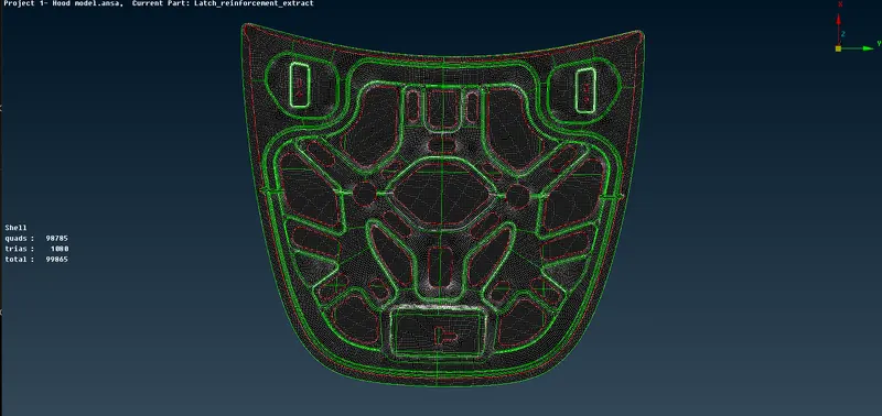
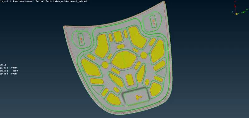
Fig 16 - Final mesh model of Hood Assembly.
Apply thickness to the final mesh:-
As the thickness is already given for Mid surface in the PID Manager, we can now see the thickness of the mesh using Draw shell as solid in quality criteria parameter.
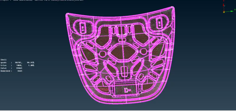
Fig 17 - Model after applying Draw shell as solid.
To check whether the surface is extracted properly, we can check by comparing the mesh surface with parent surface. If Glitching happens between two then the mid surface extracted is proper.
Results:
- No. Of Quad elements - 98785 (98.92%)
- Total No.Of Trias - 1080 (1.08%)
- No. Of OFF Elements - 0
- Total No. Of Elements - 99865.
Learning outcomes:
- Learned to extract mid surface by using offset and Feature angle tool.
- Learned to perform topology on extracted mid surface before meshing.
- Learned to solve the errors occurred during mesh by split, paste, swap and edge to perimeter option for making a closed macro area and to clear the mesh irregularities using reconstruct and smooth tools.
- Learned to assign PID's and apply varying thickness for individual faces or regions.
Conclusion:
The mid surface generation followed by shell mesh for the Hood Assembly with the objective of no OFF elements to be present in the model has been carried out successfully.