Week - 4 - 2D meshing for Plastic components
AIM:-
To perform 2-D Meshing of the given Bottle Cap Geometry using ANSA.
OBJECTIVE:-
To perform the geometrical cleaning up of the bottle cap model followed by shell meshing using the stated quality criteria. After meshing the component, the thickness has to be assigned.
| S.NO | QUALITY CRITERIA | VALUE |
| 1. | Target/Average length | 1 |
| 2. | Minimum Length | 0.5 |
| 3. | Maximum length | 3 |
| 4. | Aspect Ratio | 3 |
| 5. | Warpage | 15 |
| 6. | Skewness | 45 |
| 7. | Jacobian | 0.7 |
| 8. | Minimum Quad Angle | 45 |
| 9. | Maximum quad angle | 135 |
| 10. | Minimum Tria angle | 30 |
| 11. | Maximum Tria angle | 120 |
| 12. | Tria Percentage | 15 |
Introduction:-
The pre processing of the bottle cap geometry is as followed by the methodologies stated below,
METHODOLOGY:-
- Import the model into ANSA GUI
- Checking up for any Geometrical errors
- Extraction of Mid Surface of the component
- Topology clean up and assignment of quality criteria
- Performing Meshing using Quad and Tria elements
- Assigning separate PID for every feature.
PROCEDURE:-
STEP 1 - Import the model into ANSA GUI:-
The cad model of Bottle Cap is imported into the ANSA Interface.
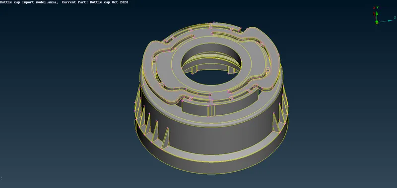
Fig 1- Bottle cap model for preprocessing is imported into ANSA.
After importing the model, the resolution is changed in order to make its features finer and to see the original shape.
The resolution of the model is changed by using the MESH > PERIMETER > Length option.
The average length of the model given here is 1.
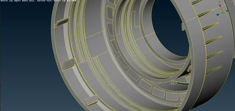
Fig 2 - Resolution of the model changed.
STEP 2 - Checking for Geometrical errors:-
The cad model after refining needs to be checked with geometry for any errors. If any errors it should be corrected in the early stage for better results.
To check for the errors,
Checks manager > Geometry
The triple cons and single cons should be turned on in order to find any overlapped surface and for any open geometry to be closed.
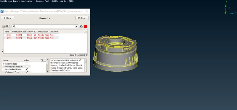
Fig 3 - Geometry errors encountered in the Bottle Cap model
The errors occurred are cleared by using the autofix option ( by right clicking on the errors ) displayed and solved.
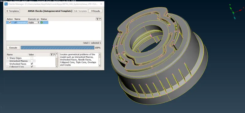
Fig 4 - The geometry is cleaned.
Step 3 -Extracting the mid surface:-
Before taking the mid surface the model has to be checked for certain measurements to decide the ways of extracting the mis durfaces.
Utilities > Measurement is used to carry out the measurement.
The measured values of each region is to be used to assign thickness to the creating Mid surface.
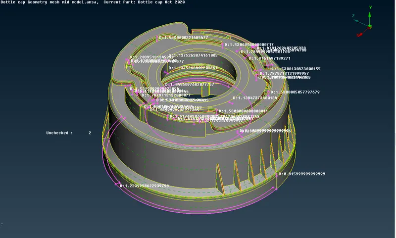
Fig 5 - Geometry Measurement
The mid surface is extracted for this model by using,
- Offset and
- Middle option
Offset :-
When the geometry has uniform thickness throught an area this method can be used to extract the mid surface. While taking the mid surface the offset value ( thickness ) must be entered correctly with the measured value, and direction of the arrow to be checked which indicates the Mid that will be created from the parent surface.
Faces > Offset > Faces
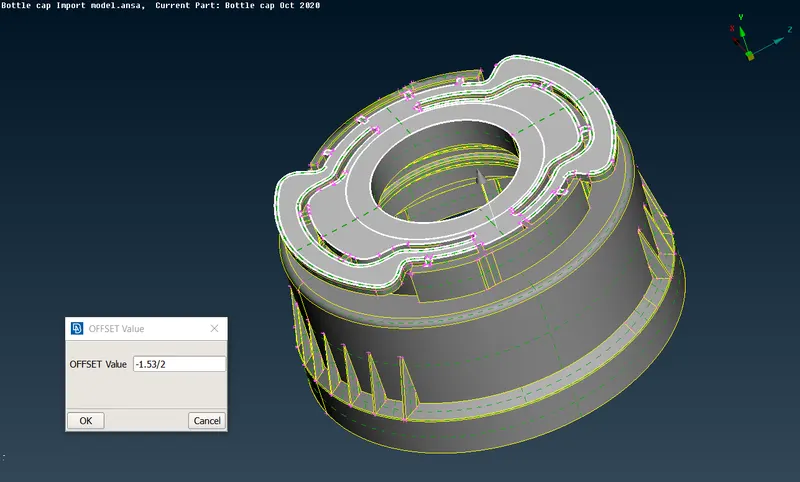
Fig - 6 - Offsetting the bottle cap Top surface
Middle:-
The middle option is used where there is no uniformity in the geometry or a region. so it is not possible to go with offset option in these areas. The middle option is used while extracting the Ribs in the model.
Faces > Middle > Multi
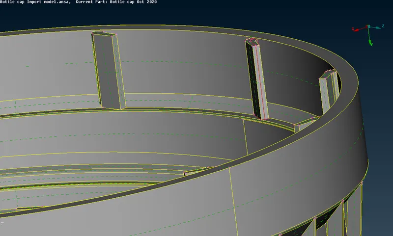
Fig 7 - Using Middle to extract mid surface in a Rib.
Extend:-
The extend option is used for extending the created mid regions to the respective surface of parent geometry where actually it emerges from.
Faces > Extend
Intersect:-
The intersect option is used in case to intersect two faces.
Using all of the above tools, the mid surface of Bottle Cap is extracted.
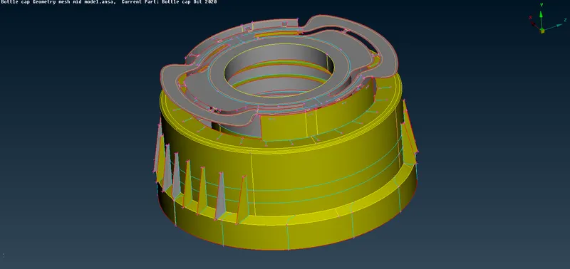
Fig 8 - Final mid surface of Bottle cap geometry
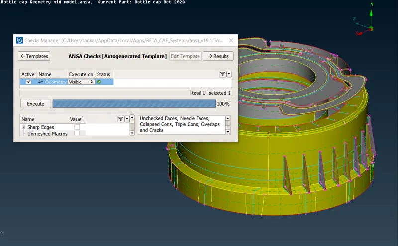
Fig 9 - Created mid surface has no errors
Step 4 - Topology clean up and Assigning the Quality Criteria:-
The topology clean up means removing the extra cuts and hot points over the surface of the component. It includes measurement at certain areas where the area falls below minimum criteria of the element length followed by its defeaturing.
Assigning the stated quality criteria, Parameters and performing surface meshing:-
The quality criteria is followed before performing the mesh according to the requirement,
Minimum length - 0.5
Maximum Length - 3
The above mentioned lengths are used to define the distance between the nodes over the surfaces, any two nodes having a distance less than 0.3 and 3 will fail for element size.
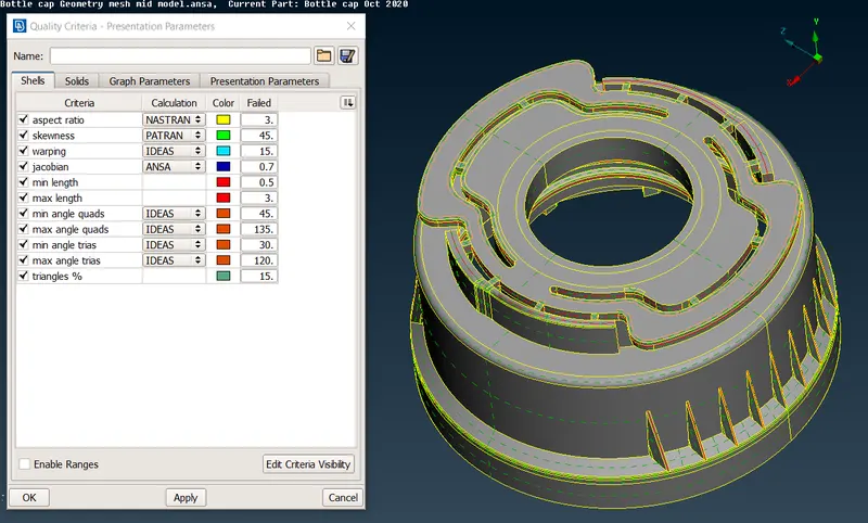
Fig 10 - Quality criteria
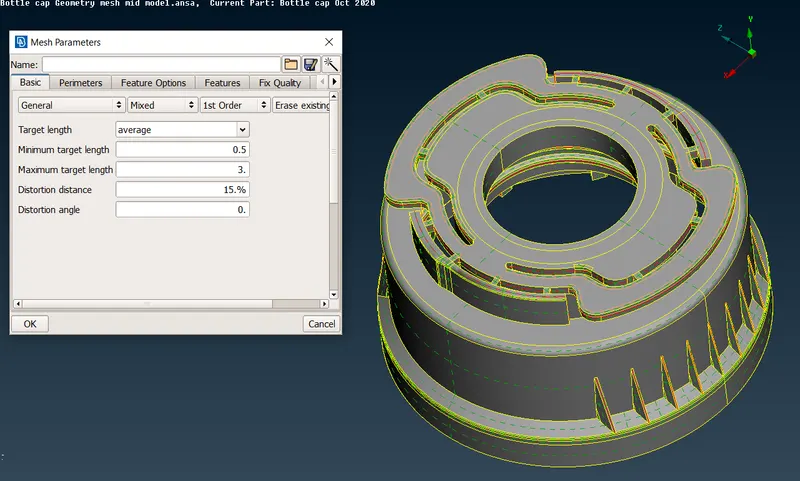
Fig 11 - Mesh parameters
Step 5 - Performing meshing using Quad and Tria elements:-
Before meshing we need to check for the define the length of the perimeter s per quality criteria. The length is 1 here. This is to ensure that adjacent nodes have a distance of 1 between them.
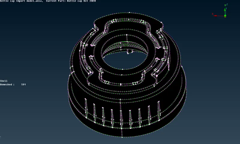
Fig 12 - Average length as 1 is applied in the above model.
While performing meshing, keep in mind to avoid the rotating quads, opposite tria elements with proper mesh flow.
Switch to Hidden Mode then start the mesh generation. The mesh generation is carried out using two methods,
- Best
- Spot mesh
Rectifying the mesh errors:-
The errors formed during the meshing of the mid surface is eliminated by using the following options,
- Reconstruct
- Smooth
- Split and
- Paste option.
The reconstruct option helps in reconstruction of the mesh elements in a bettery way than the previously applied one, which helps to improve the mesh flow in that particular area.
MESH > SHELL MESH > RECONSTRUCT
The Smooth operation is used commonly after reconstructing to make the mesh aligned throughout the reconstructed area.
MESH > SHELL MESH > SMOOTH
The split and paste options are used to solve the rotating quads, opposite tria elements to split and paste them according to the mesh flow.
MESH > ELEMENTS > SPLIT
The Paste is used to remove the opposite tria near to each other.
GRIDS > PASTE > PASTE NODE PAIRS > COG
In certain regions, there are errors, thst cannot be removed. Like in the below figure we can see the region where Triple cons present, so we cannot remove the triple cons even if we try. So in these areas the errors cannot be solved.
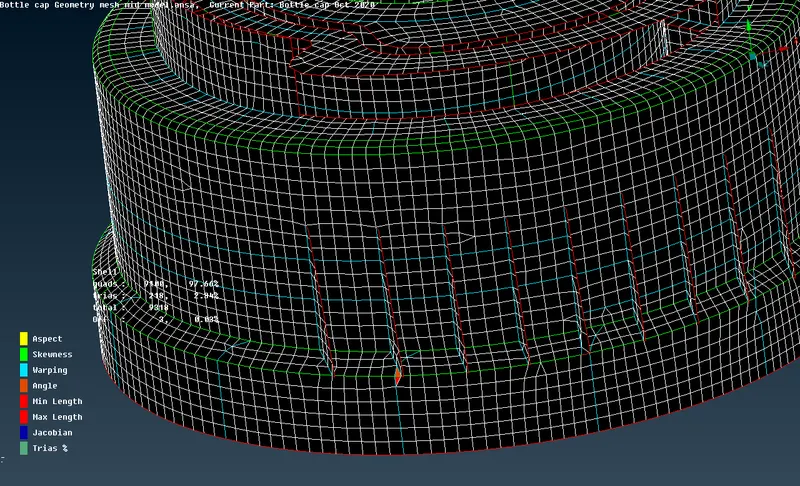
Fig 13 - Min length error due to triple cons present in the area
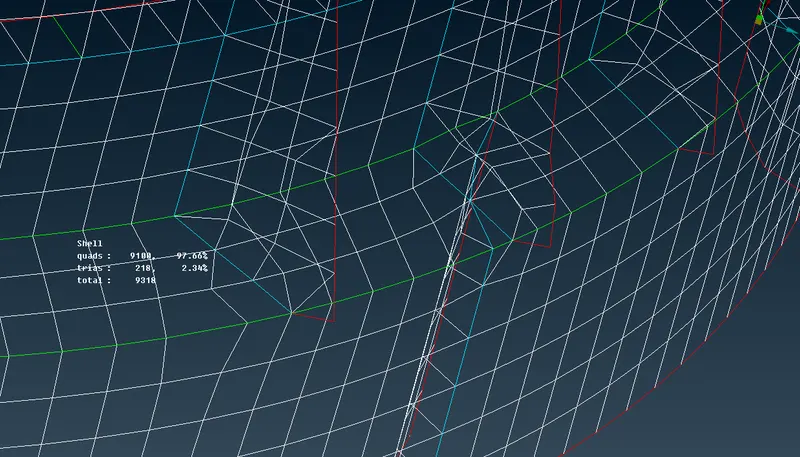
Fig 14 - Triple cons in the bottom rib and fillet area.
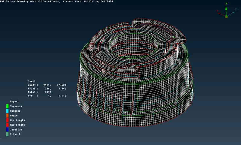
Fig 15 - Final mesh model
Step 6 - Assigning separate PID for every feature:-
PID Is nothing but the property ID. If the component is having a constant thickness throughout it, then its ok to have a single property ID, but in case of varying thickness its necessary to assign separate Pid's to each and every region.
while assigning the property Id each region has separate thickness with respect to its parent geometry, so the thickness is assigned from the parent measurements to the regions of the Mid surface and separate colours are given to each Pid's for better visual understanding and differentiating of the regions.
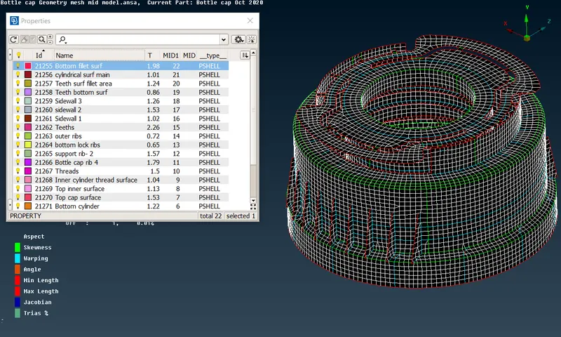
Fig 16 - Assigning thickness to each feature
Apply Thickness to the final mesh:-
AS we assigned thickness to the midsurface in the PID Manager, we can now able to see the thickness of the mesh by enabling Draw Shell as Solid in Quality Criteria.
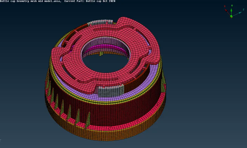
Fig 17 - Model after applying thickness
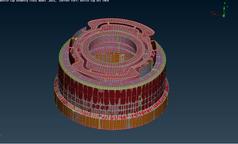
Fig - 18 Comparing the mid surface to the parent Geometry.
To see if the surface is extracted properly, we can check by comparing these mesh surfaces with parent surface. IF Glitching happens between two then the mid surface is extracted properly.
RESULTS:-
| No. of Quad Elements | No of Tria Elements | No of Off Elements | Total no of elements |
| 9089 (97.66 % ) | 216 (2.34 % ) | 1 (0.01% ) | 9305 |
LEARNING OUTCOMES :-
- Learned to extract mid surface by using tools such as offset and middle option for this model.
- Learned to extract or create a mid surface by using curves middle, Cons to curve tools.
- Learned to solve rotating quads formed in critical areas to avoid improper mesh flow pattern.
- Learned to solve the element failures by using split, paste, Edge to perimeter and other tools such as reconstruct and smooth.
- Learned to measure thickness in critical fillet areas and combination of thickness for varying thickness regions.
- Learned with extend and intersection tools and how they work in the areas.
- Learned to defeature in critical areas to avoid unwanted quality crieria errors, especially in Triple con regions.
CONCLUSION:-
The extraction of mid surface followed by the shell mesh for the Bottle cap geometry model is completed sucessfully under the given quality criteria Parameters . Some errorsin the model cannot be resolved due to the intersection of faces forming triple cons at the region of ribs causing minimum length criteria error.