Week 6 - Creating connection for Rear door
AIM:To learn how to make connections between parts of the FE model in ANSA.
OBJECTIVE: To Create and Apply different PIDs for different components. By using the same technique and the elements as shown in the video, Perform suitable connections for the given Rear door FE model.
PROCEDURE:
- Import the FE model into ANSA and take a look at the model once and try to understand that what connections to be created for different components.
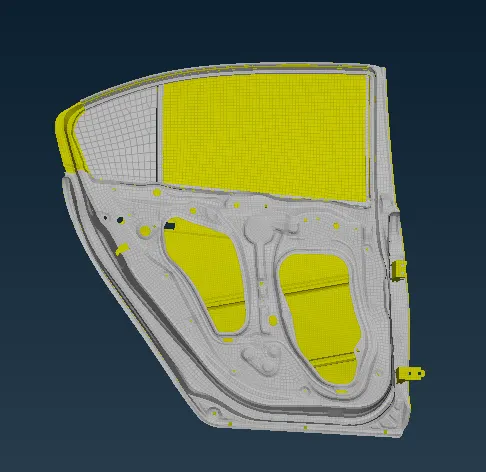
- Imported model.
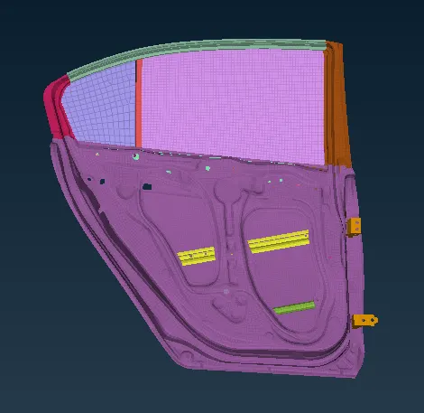
- Then, assign PID's for different components. The PID's assigned for the given model as shown below.
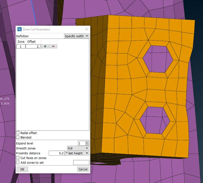
- And zone cuts are created at the bolt connection regions.
- To create zone cut go to mesh panel>shell mesh>zone cut.
- Now, make necessary connections at the particular area. To make connection go to >Nastran deck>elements>RBE2>many nodes>select slave nodes and master node create link.
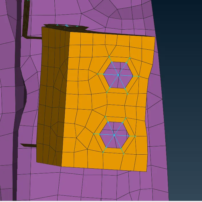
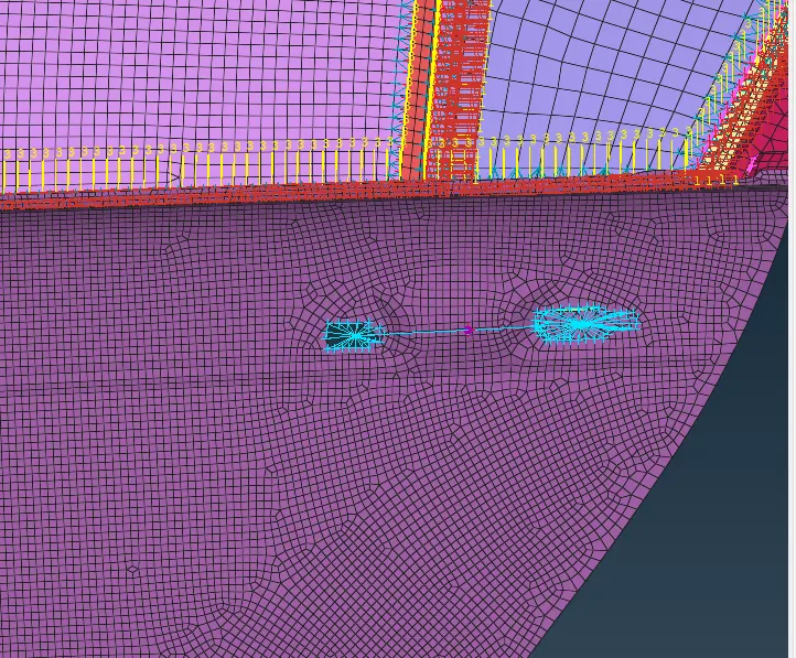
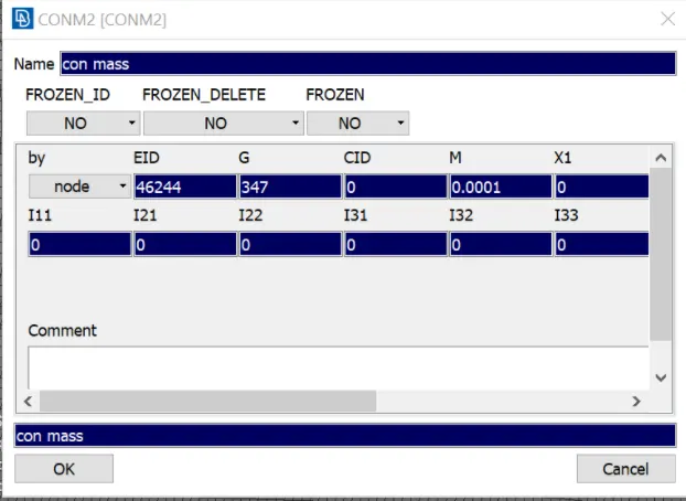
- And for the handle the connections are made as shown below. RBE2 links are used to rigidize the connections. And con mass is added.
- CONMi: It is referred to as con mass. It is basically a concentrated mass connection where a point is created for representing the weight of it. We must give the mass in tonnes. Here we gave the handle mass as 100 grams which is 0.0001 ton.
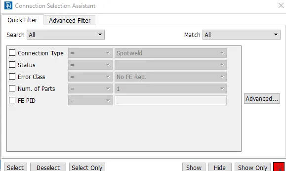
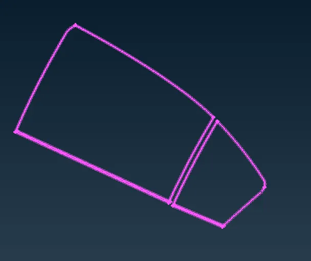
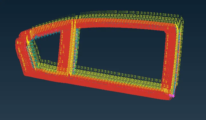
- CBUSH Connection: This connection for the glass is always given in closed. 1st create curves using Perimeter --> FEAt2Curve option which is available in mesh mode. Then convert those curves to spot lines. Now using connections manager assign ‘P’, ‘S’ values and select RBE3-CBUSH-RBE3 as FE type for generating CBUSH connection.
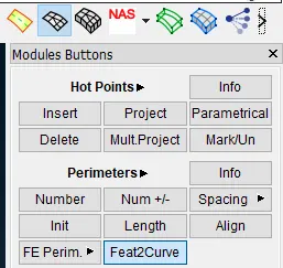
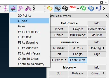
Curves created and conveted to spot line.
RBE3-CBUSH-RBE3 connections generated.
- To create spot weld connections, create a 3D point by using on COG option in the topo panel Topo>points>On cog
- then, convert that 3D point to spotweld point.
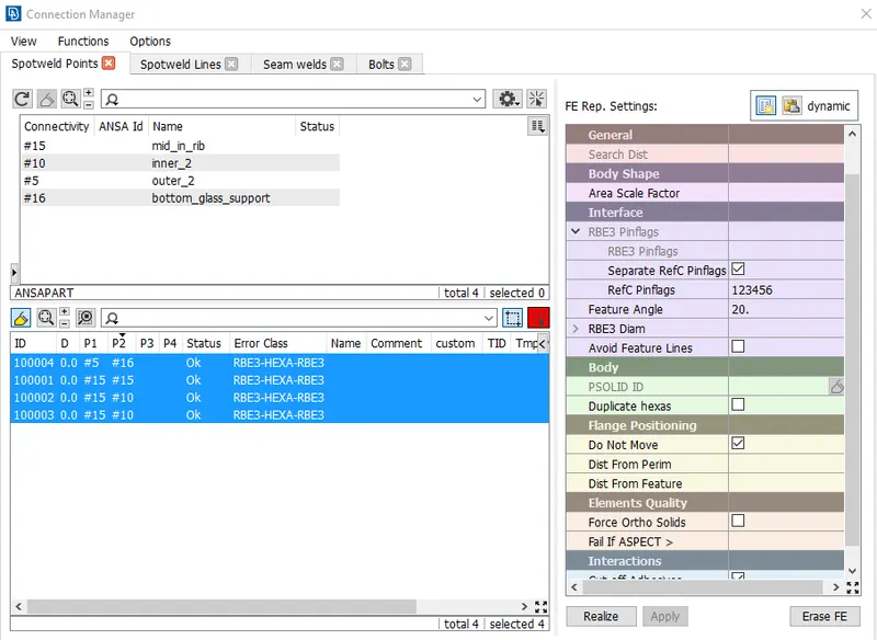
- And go to connection manager and select that point and assign P1, P2 and then select TID FE Rep.type as RBE3-HEXA-RBE3 and there make necessary changes and create PSOLID ID there and assign it.
- Then, click apply and realize. All steps are shown below in the images.
- Edges selected to cretae COG point.
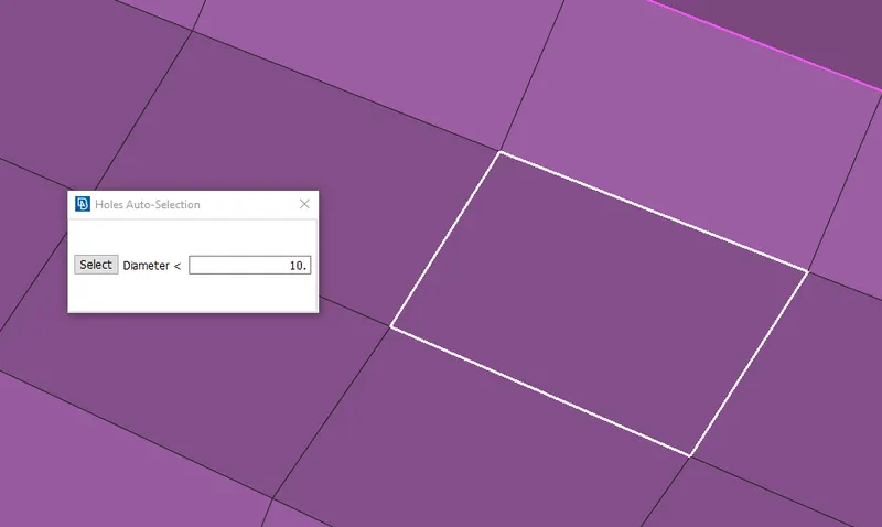
- 3D point has been created.
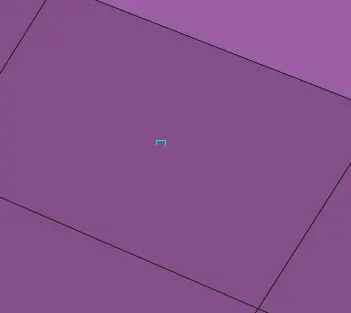
- Converting the 3D point to spot weld point.
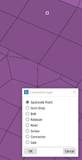
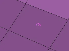
- spot weld point has been generated.
- to select the weld point go to connection manager and select the point as shown below.
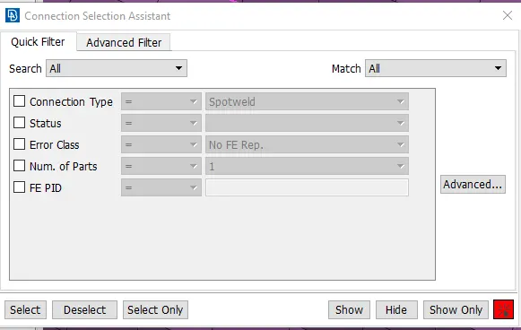
- After selection and middle click confirmation th ebelow window wil pop up, there p1,p2 and search distance are to be assigned and here make sure that in th interface>Ref Pinflags are constrained in all directions 123456.
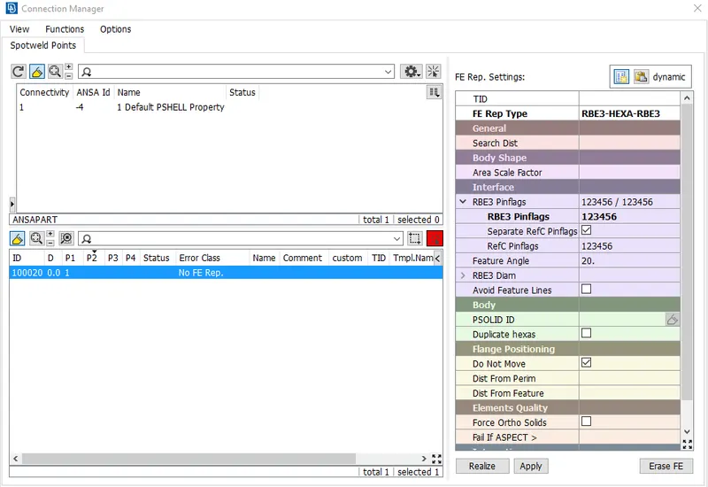
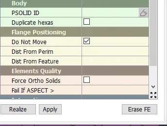
- To define the specific property for the connection.
- Select the id tab and press the Shift and / in your keyboard
- It will open the respective property tab then you can assign the older id or else you can create the new id also by right-clicking the screen you can see the new option there you can create the new id.
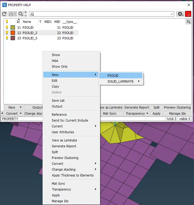
- Double click the required property in the property tab and the selected property ID will be displayed in the ID section.
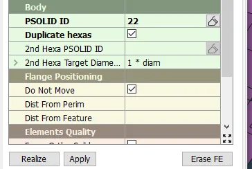
- Click apply and realize it will create spot welding.
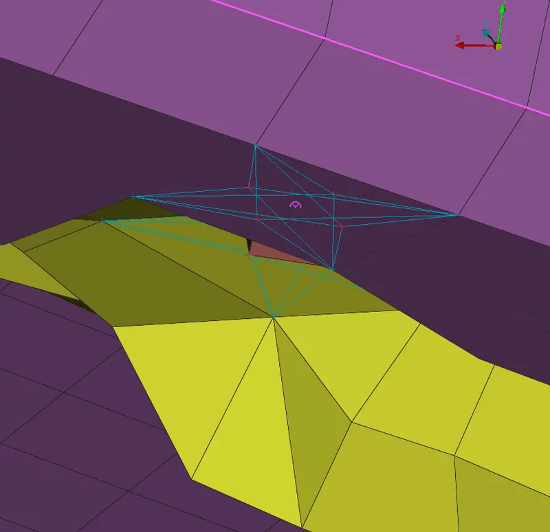
- To create seam weld connection convert length of the FE to be welded into curve – then convert the curve into seam line – then go to connection manager select the seam line – select the connections as overlap joint/y- joint – give search distance – select the pid to be connected – apply and realize.
- creating curve using feat2curve option in Mesh>perimeter>feat2curve.
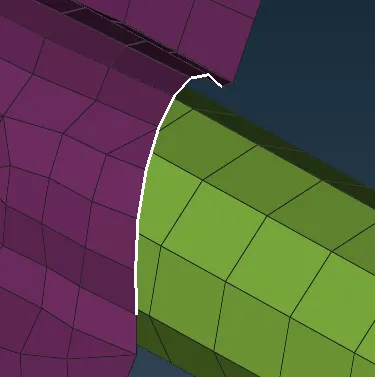
- curve has converted to seamline.
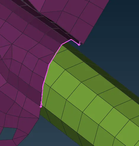
- Using connection manager to select the seamline and to assign the property and creating seam weld connection.
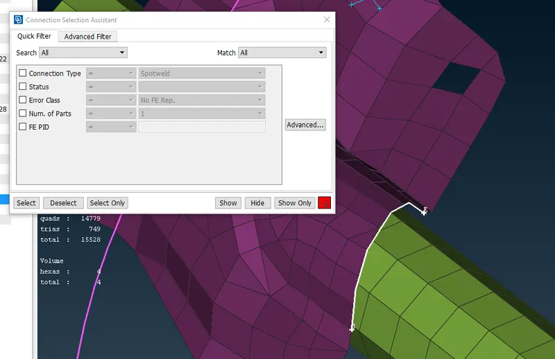
- On middle click confirmation in the mouse a window will pop up which is shown below. Assign p1, p2 values and select FE Rep Type as OVERLAP-SHELL-CLOSED and there in general>select base sheet. And create Property ID and assign it.
- And then click apply and realize it will create seam weld connection.
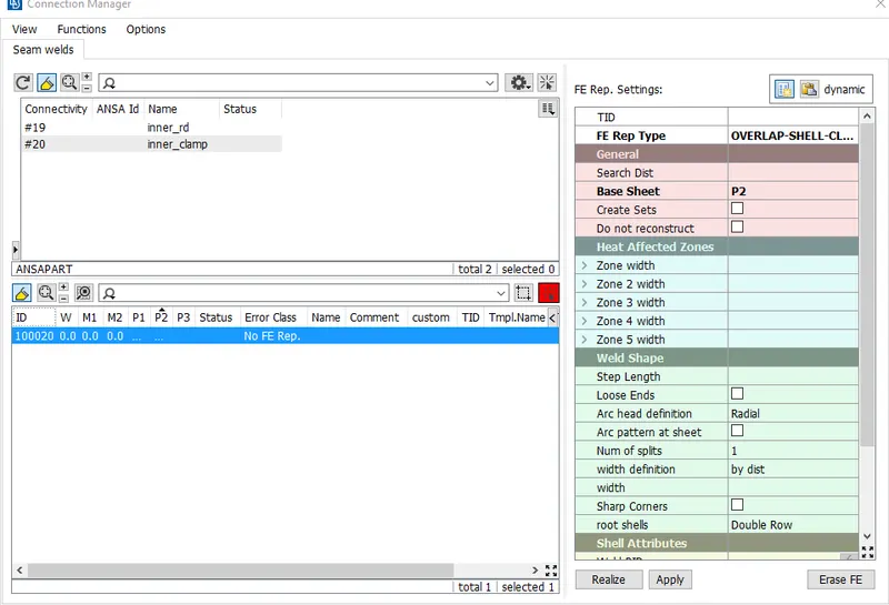
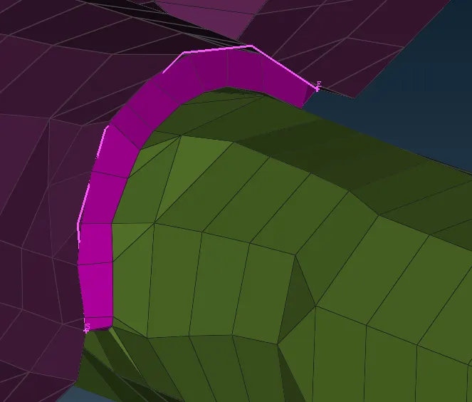
- Weld connection has been created.
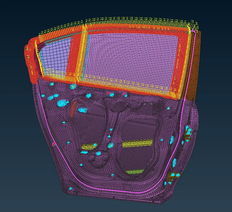
- Whether strip (or simply rubber strip) can be assigned in ANSA. Create curves using Perimeter --> FEAt2Curve option. Then convert those curves to seam line. This acts as a rubber strip during simulation.
CONCLUSION:
Through this challenge I have learned to make RBE2 and RBE3 connections to rigidize the system with appropriate connections like spot weld (RBE3-HEXA-RBE3), seam weld(OVERLAP-SHELL-CLOSED), and CBUSH (RBE3-CBUSH-RBE3) connections.