Week 6 - Creating connection for Rear door
AIM
- To deploy connections for the given Rear Door FE Model.
PROCEDURE
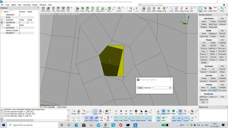
- In order to establish the bolt connection, first we have to create a COG point as shown below.
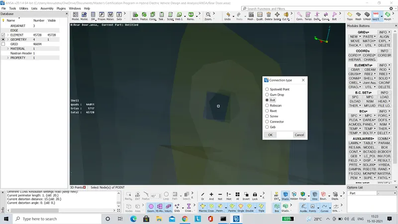
- Then using the 'Convert' tool, the previously generated COG point is converted to a bolt connection type as shown below.
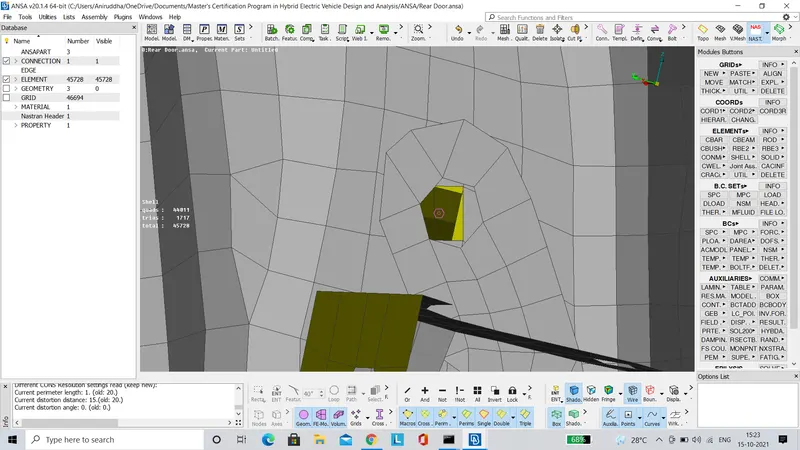
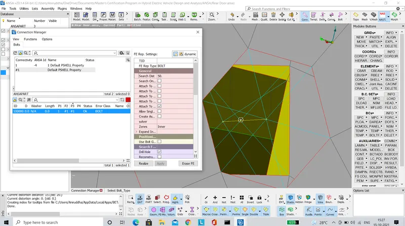
- Now using the 'Connection Manager' we have to establish a RBE2 link between the holes.
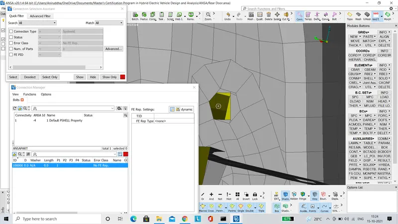
- The FE Rep type is set to 'BOLT'. The 'P1', 'P2' & 'P3' surfaces are selected accordingly. The search distance is set to 50. Finally all the conditions are applied and then the connection is realised as shown in the image below.
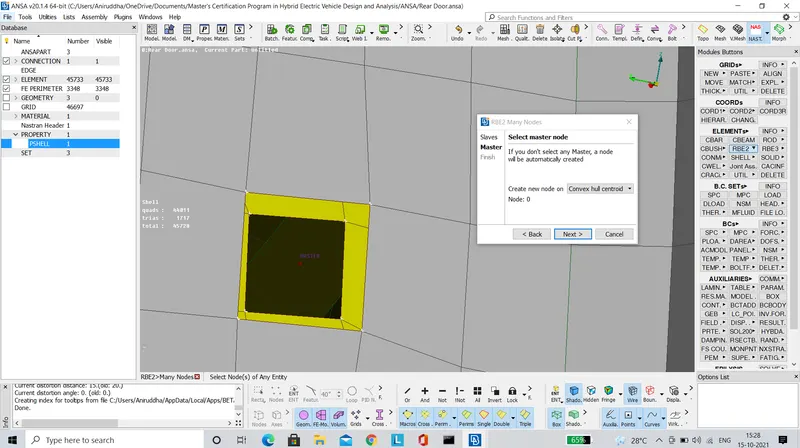
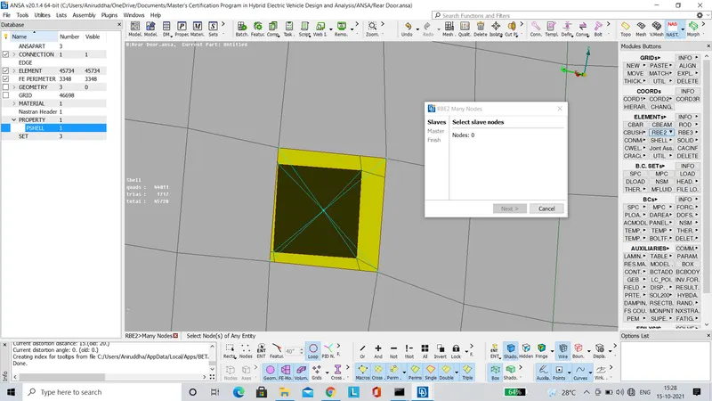
- For rest of the holes, a cluster type RBE2 connection is established using the 'RBE2' tool present under the 'Elements' panel of the 'NASTRAN' deck as shown in the images below.
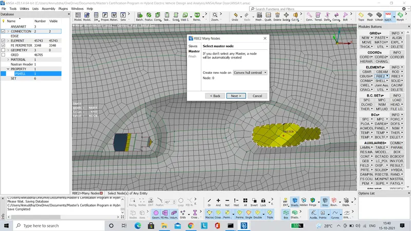
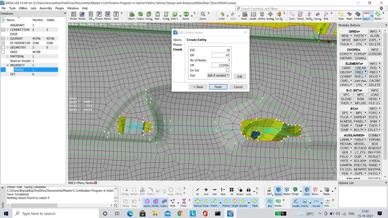
- The handle of the door is not represented by a FE model, rather it represented by a point mass. To begin with the latches of the handle are represented by RBE2 elements as shown in the images below.
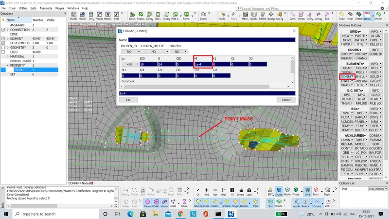
- Finally a point mass is added on the master slave present on the link between the two latches using the 'CONM2' tool as shown in the images below. The mass is set to 100 grams, denoted in tonnes.
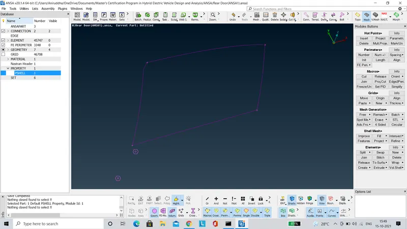
- Finally the Bush type connections have to created between the door panel and the glass window.Using the 'Feature2Curves' tool, we have to create a curve to represent the boundary of the window as shown in the images below.

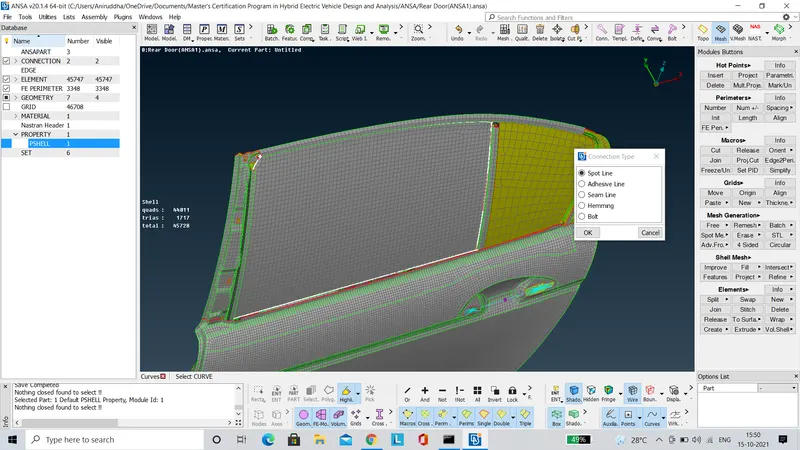
- The curve generated is converted to a 'Spot Line' using the 'Convert' tool as shown below.
- Now using the 'Connection Manager' we have to establish 'RBE3-CBUSH-RBE3' connection between the glass window and the door panel.
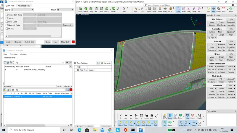
- The FE Rep type is set to 'RBE3-CBUSH-RBE3'. The 'P1' & 'P2' surfaces are selected accordingly. The search distance is set to 100. The value of 'S' is set to half of the distance between the glass door and the door panel ie 10 in our case. Finally all the conditions are applied and then the connection is realised as shown in the image below.
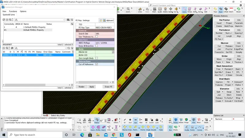
- Each 'Bush' element created has its own local co-ordinate axis as shown in the image below.
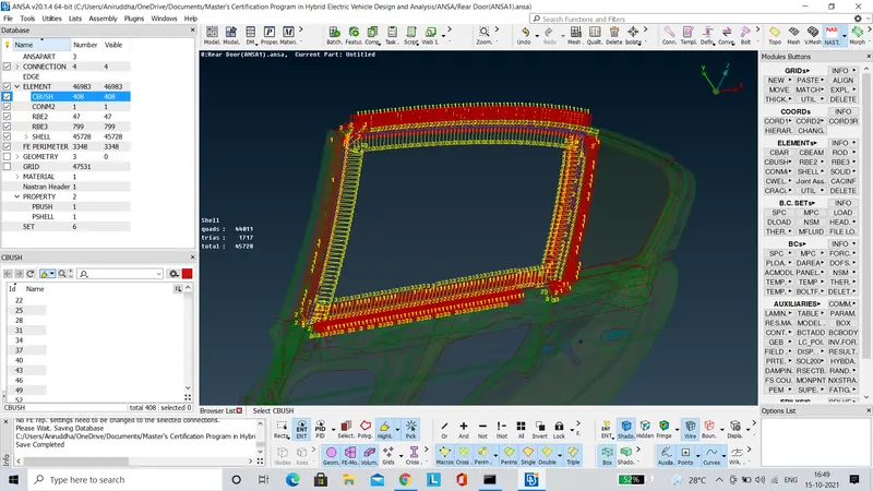
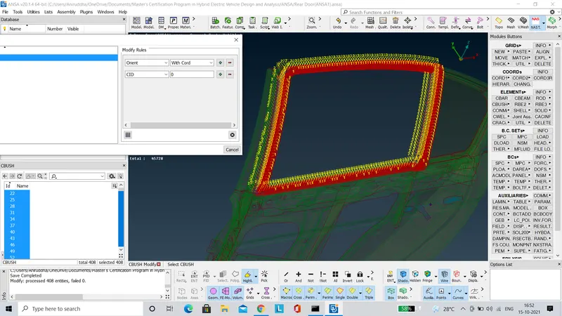
- But as per industry standards, the orientation of the 'Bush' elements should be aligned with co-ordinate axis of the door model. To achieve this, all the bush elements are selected & then their orientation is modified as shown in the image below.
LEARNING OUTCOME
- Various tools concerned with establishing connections between different features on a FE Model were learnt during the course of this project.
CONCLUSION
- The connections have been established on the Rear Door FE Model as required.