Week 6:- Clamp Unit & Pin-Clamp Unit Design Challenge
Challenge:
1.Design 3 Different types of Swivel Clamp Unit with Different Riser, Blade, and Clamp Arm for the given Car Panel. Maintain the stroke as 100mm
2. Design a Pin-Clamp Unit for the given Car Panel.
Ans:-
3-2-1 principle
Every part has 6 degrees of freedom (3 linear + 3 rotaries) which need to be arrested to ensure the proper location of the part in space. The location principle used to achieve this is called the 3-2-1 principle.
Any rectangular body may have three axes along the x-axis, y-axis, and z-axis. It can move along any of these axes or any of its movement can be released to these three axes. At the same time, the body can also rotate about these axes too. So the total degree of freedom of the body along which it can move is six. For processing the body it is required to restrain all the degrees of freedom (DOF) by arranging suitable locating points and then clamping it in a fixed and required position
The basic principle used to locate the points is desirable below. Six Points Location of a Rectangular Block. It is made to rest on several points on the jig body.
3 stands For - Minimum 3 Rests with clamps to establish a part plane thus restricting 1 up-down motion plus 2 Rotary motion. 3 locators position a part in a primary plane or direction. Provide a rest to the workpiece on three points on the bottom x-y surface. This will stop the movement along the z-axis, rotation concerning the x-axis and y-axis. Supporting it on the three points is considered better support than one point or two points.
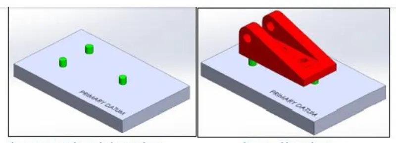
Fig 1:- Primary Datum
For the primary locating datum, the area of the triangle formed by the three locating points should be as large as possible.
2 stands For – Two locating pins in a round hole that restricts motion in the two directions in the established plane. 2 locators then position the part in a second direction (e.g., in/out). Rest the workpiece on two points of the side surface (x-z), this will fix the movement of the workpiece along the y-axis and rotation concerning the z-axis
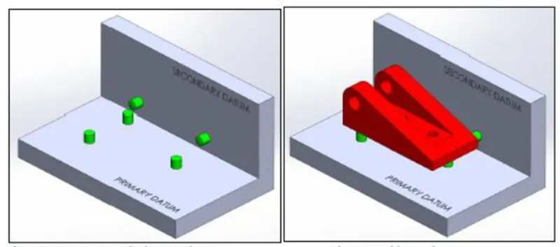
Fig 2:- Secondary Datum
The distance between the two locating points is as large as possible for the secondary locating datum, and the line segment connecting the two locating points should be parallel to the primary locating datum if possible.
1 stands For – A Round locating Pin in a slot that restricts the rotary motion in the established plane about the round pin. 1 locator for the tertiary direction. Provide support at one point of the adjacent surface (y-z) that will fix other remaining free movements.
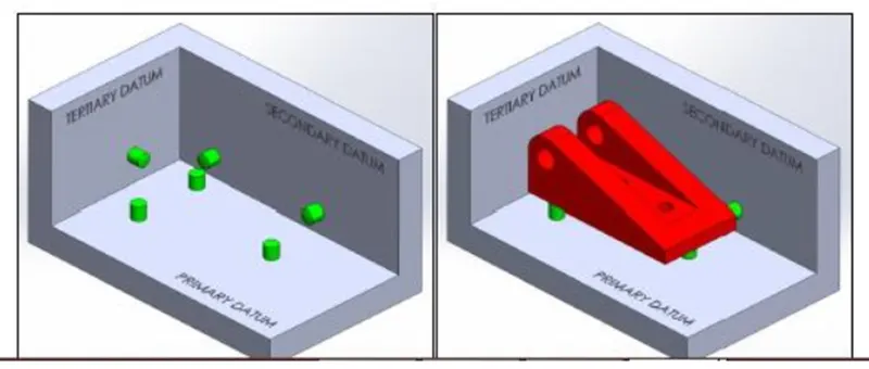
Fig 3:- Tertiary Datum
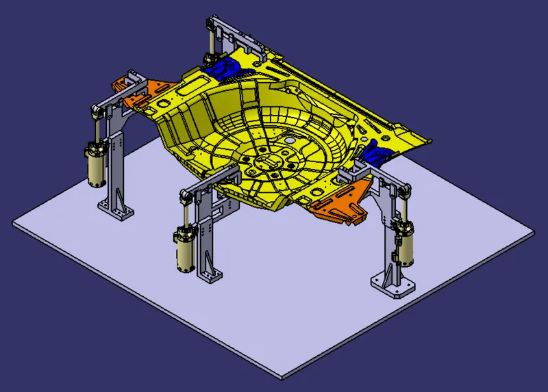
Fig 4:- Clamp unit arrangement to control DOF of the panel
All the DOF of the given panel is controlled by different Clamp units & rest units.
Swivel clamp unit
Clamp unit: - A clamp unit is a unit designed to clamp/hold the car panel with NC blocks/ Mylar/ rest by using a pneumatic clamp cylinder & below are different parts of a clamp unit in general. Usually clamp open position is 90°. Fingers are attached to the clamp Mylar. In a clamp unit shimming to one side is more than enough because it will restrict translation motion in upward & downward directions only. There is another type of clamp unit known as the swivel type. There is a pivot pin around which the clamp arm rotates.
CLAMP PLAN:
- The customer provides the clamp plan which consists of the position of the clamp, pins, rests and dump, etc.
- It has the exact coordination of these components and in addition, it also has the hole’s dimensions and tolerances.
- As this is critical input data, it must not be modified.
- In case the spot for weld and the clamp position is nearby and it may create a problem later and there is a need to change the position of the clamp, the same must be done so with the permission of the customer as it will be easy for the customer to make changes from his side also.
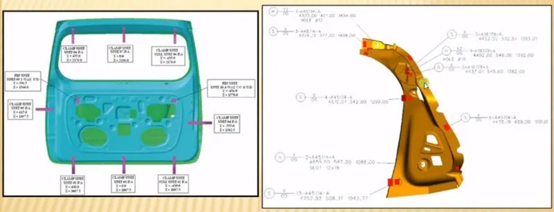
Fig 5:- Clamp Plan
Factors should be considered while designing a clamp unit:
- There should be adequate space between the cylinder & another part like the riser, car panel because the cylinder moves or swing while opening & closing
- Pin clamp unit used where two panels or components are located for welding.
- Clamping is make in such a way that it clamps two car panels at once
- All parts should snap & butt properly to each other.
- Make sure that parts of the clamping unit are 10 to 12 mm away from the car panel so they do not damage the car panel
- Avoid any clash. It will not arise an issue at assembly.
Below are the general parts of the swivel clamp unit.
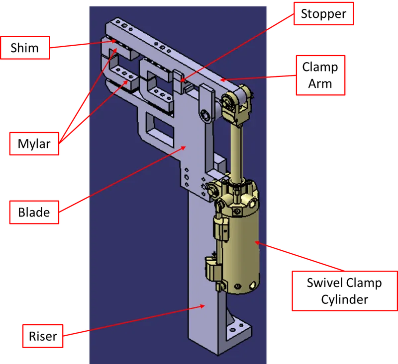
Fig 6:- Swivel clamp unit
- Clamp Cylinder
- Clamp Arm
- Mylar
- Blade
- Shims
- Bush
- Riser
Clamp Cylinder:
Cylinder designation: In this unit, we used a Clevis cylinder for clamping designated as CKG_1B_63_100Y
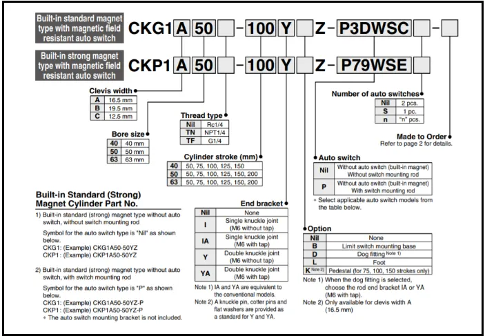
Nomenclature of the cylinder as below:
CKG1: Series of cylinder
B: Clevis width is 19.5 mm.
63: Bore size
100: Stroke of cylinder
Y: End bracket i.e. double knuckle joint (M6 without tap)
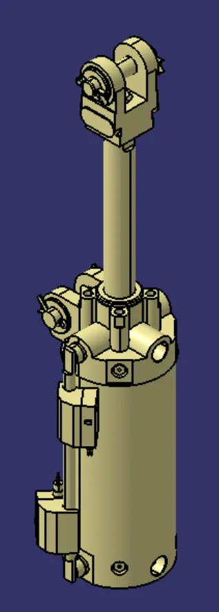
Fig 7: Swivel clamp
Clamp arm: It is the part to which the clamp mylar is mounted & also clamp cylinder is attached to the end of the arm with the use of a clevis pin. It has two plates of 8 mm thickness welded & helps in rotating of clamp arm about pivoting point of the blade.
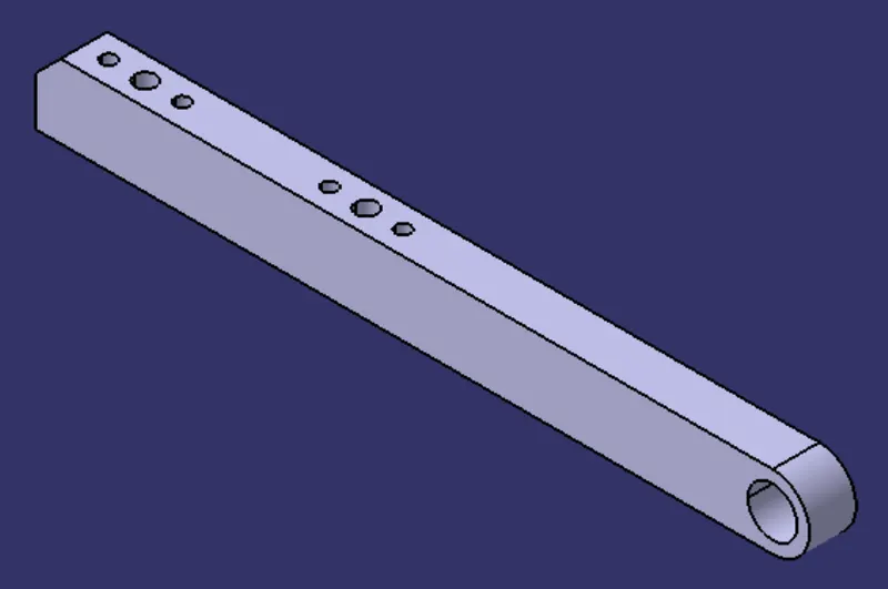
Fig 8: Swivel arm
Mylar/NC Block
- NC blocks or popularly also known as Mylar is the ones that hold the panel.
- It prevents the panel from deforming while welding.
- They always come in pairs.
- Top Mylar is known as clamping Mylar and bottom Mylar is known as resting Mylar.
Few points to remember about Mylar:
- Generally, Mylar clamping block clamp cross section (the area in the contact panel) is considered as 20mmx20mm.
- Most of the OEMs/Tier 1 prefer Mylar to have a 5mm allowance material for machining. Most Mylar is CNC machined if it is clamping 3D profile.
- Depending on the angle of the cross-section, Mylar will be shimming either in one direction or in 2 directions.
- The general Thumb rule is if the section is inclined more than 15 deg or the clamping surface is a 3D profile then 2-direction shimming is provided. The reason is simple mathematics. The equation of inclined line/ plane will be having 2 parameters to control and we control with shimming in 2 directions. Less than 15 deg does not mean that there are not 2 parameters. These are there but they are neglected if the angle is less than 15 deg.
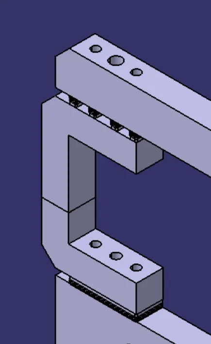
Fig 9: Mylar/NC Block
Blade:- The plate which connects Riser to the Block/Clamp cylinder is named Blade. This plate plays an important role in building the unit. The plate can be of any shape. But we need to keep in mind that the plate should be as compact as possible.
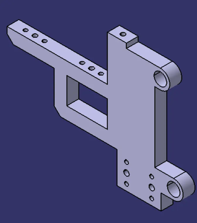
Fig 10: Blade
Stopper:
The function of the stopper is to restrict the motion of the clamp arm. It avoids clamp-arm to rotate beyond the limit. It has two parts male & female.
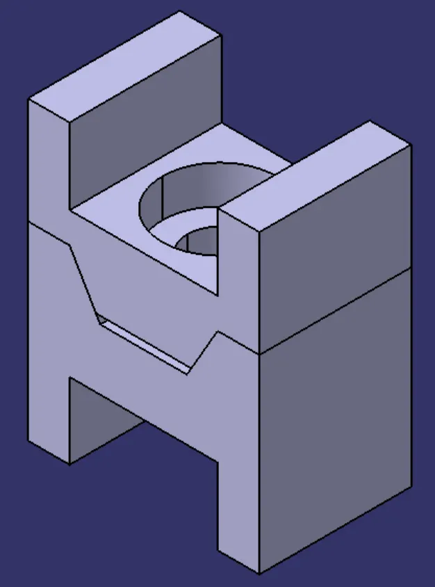
Fig11: Stopper Assy
Shim:- Shims & Spacers are some standard parts in general, which are used for adjustments of locators (NC Blocks & pin retainers) for desired values for the precise working of a unit concerning car parts. In general to adjust the design to manufacturing deviation.
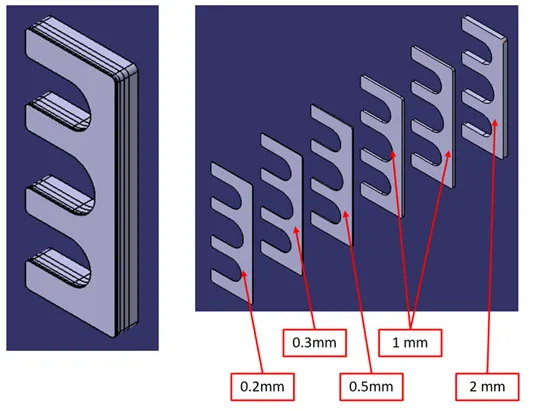
Fig 12: Shim/Spacer
Bush is used while inserting pins into holes.
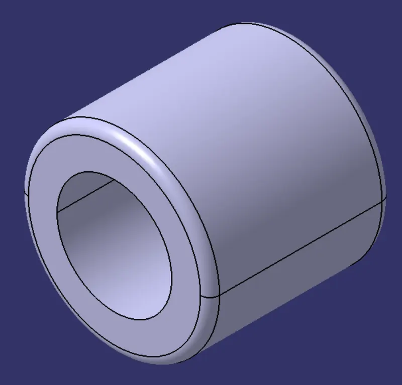
Fig 13: Bush
Riser:- The part which is mounted on the base plate and holds a blade or pin cylinder on it is called Riser. The riser can be a Standard Part or a manufactured part, it varies from project to project. A riser can be a Single part or welded part. Standard risers also have various shapes and sizes.
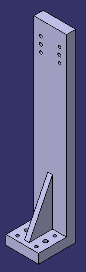
Fig 14: Riser
Swivel clamp unit-1
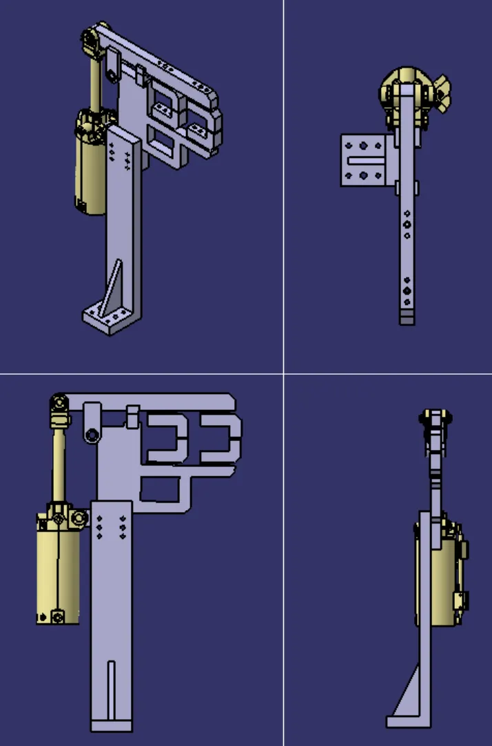
Fig 15: Swivel clamp unit-1
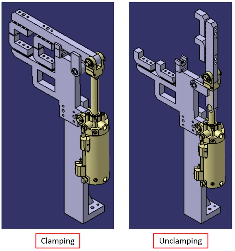
Fig 16: Swivel clamp unit-1 Clamping & unclamping
Swivel clamp unit-2
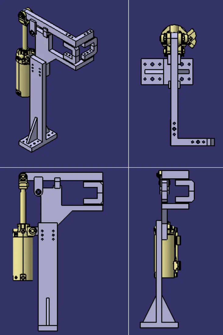
Fig 17: Swivel clamp unit-2
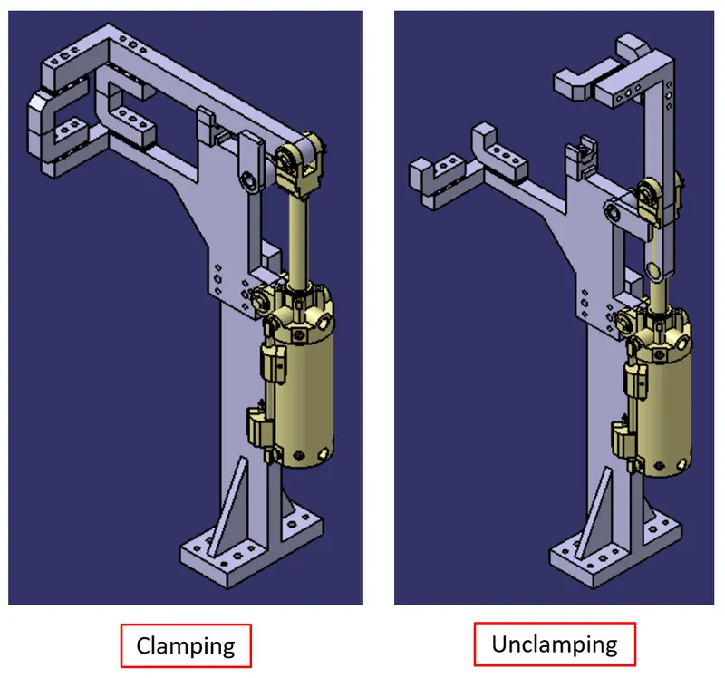
Fig 18: Swivel clamp unit-2 Clamping & unclamping
Swivel clamp unit-3
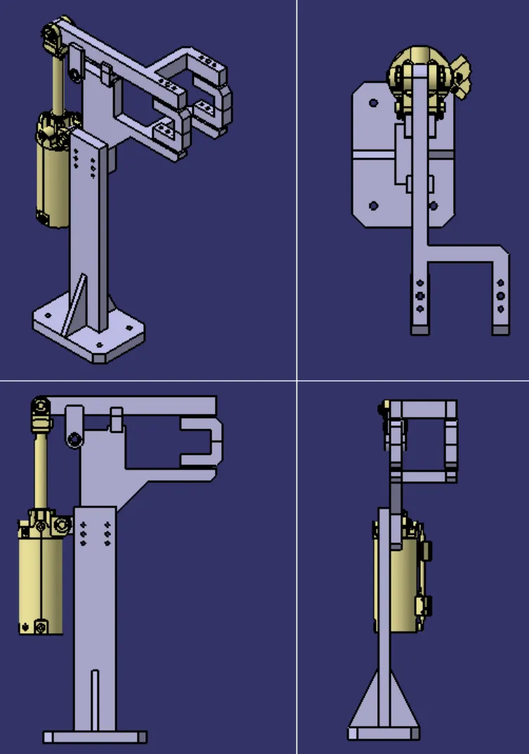
Fig 19: Swivel clamp unit-3
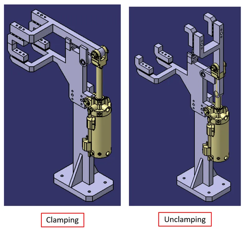
Fig 20: Swivel clamp unit-3 Clamping & unclamping
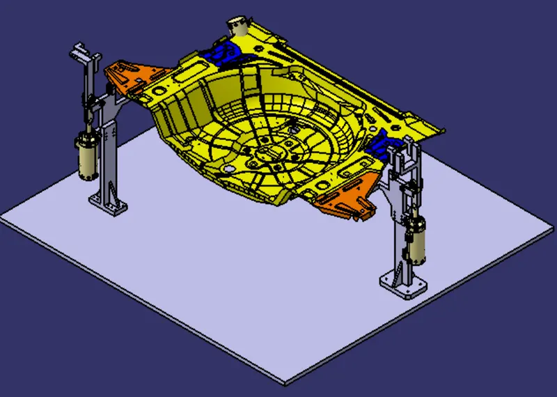
Fig 21: Swivel clamp units with panel-1 (isometric view-1)
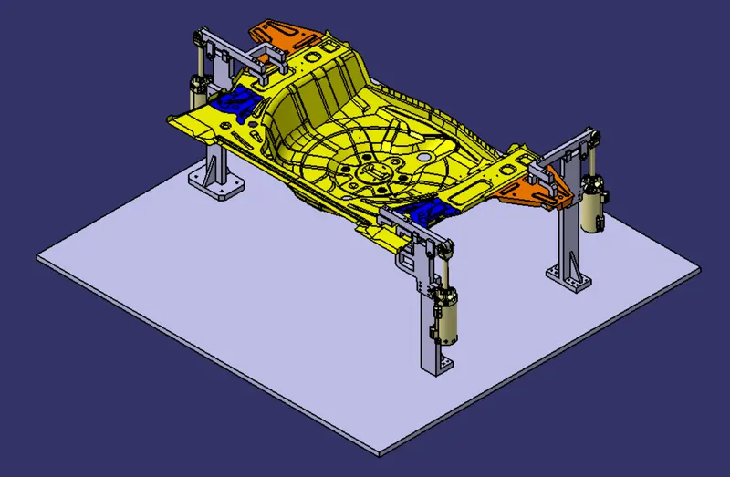
Fig 22: Swivel clamp units with panel (isometric view-2)
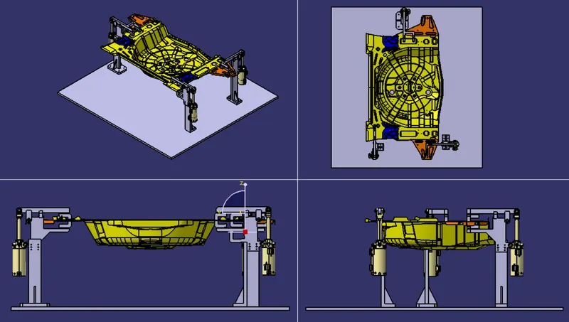
Fig 23: Swivel clamp units with panel (all view)
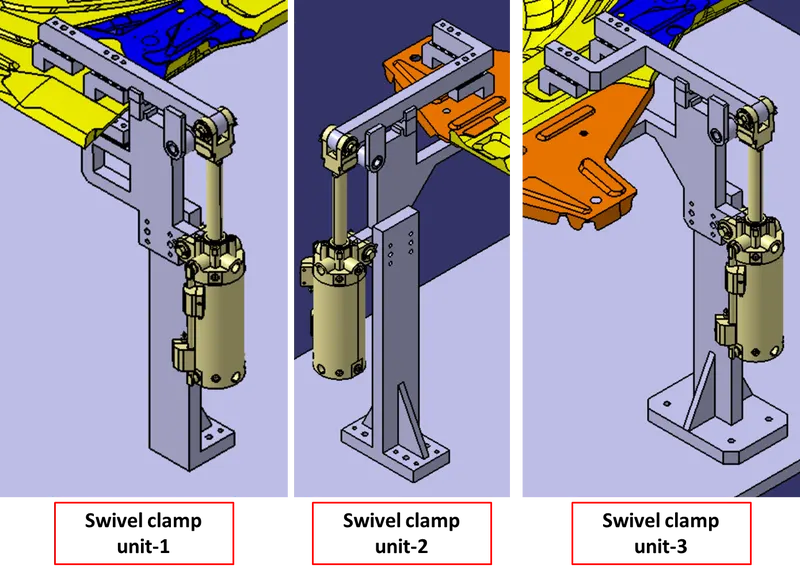
Fig 24: Swivel clamp units
2. Pin Unit
Pin Unit:- Pin unit is a unit designed to locate the car panel using Pin. The pin unit is used to lock the rotational position of the panel.
Fundamentals of pin unit design
- it is necessary to have 2 pins to locate a car panel & here one pin must arrest 4 way (4 translational) & other must arrest 2 way (i.e. 2 rotational) of a car panel.
- The axis of the car panel hole & the axis of the pin should be the same (in general)
- The pin tolerance for a geo pin will be of closer tolerance i.e. -0.15mm & for a re-spot pin is -0.28mm
- Pin should engage 3 to 5 mm from the car panel entry surface.
- All pins should be accommodated with 2-way adjustable shims irrespective of the direction of arresting.
- Round pins should be used if the hole is round in case of 4-way arresting of the car part.
- Round pins can be used for 2 way arresting of car parts only if the hole is slot.
- Diamond pins should be used in case of 2-way arresting of car part if the hole is round
- Diamond pins should be used in case of 4-way arresting of the car part if the hole is slotted.
There are mainly 2 types of pin units
- Fixed Pin Unit
- Retractable Pin Unit
Fixed Pin Unit Design
Fixed Pin Unit:- The pin’s position is fixed in a Fixed Pin Unit.
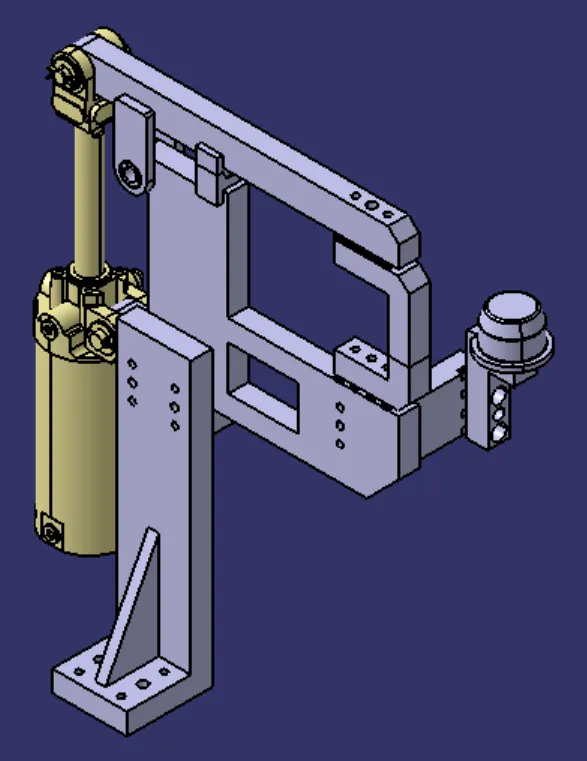
Fig 25:- Pin-clamp Unit
A typical Fixed Pin unit consists of the following parts.
- Clamp Cylinder
- Clamp Arm
- Mylar
- Blade
- Shims
- Bush
- Riser
- Pin
- Pin Retainer
- L-Block
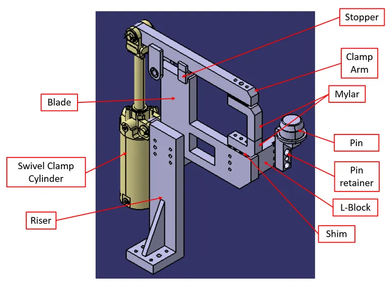
Fig 26:- Pin-clamp Unit (all parts)
Pin:- Pins are used to locking the rotational movement of the panel. Generally, there are two types of Pins, one is Round Pin and one is a Diamond pin. We use two and three-directional shimming for pins as per the angle of the pin w.r.t. the carline. In some cases, we use a collared pin, when the pin is supposed to support the panel as well. For this kind of pin, we provide 3-way shimming irrespective of pin angle to the carline.
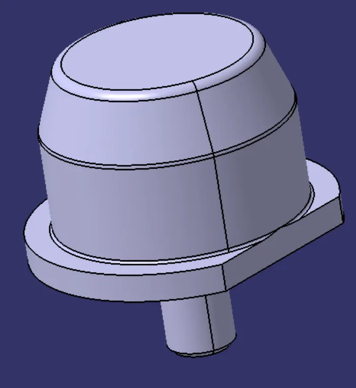
Fig 27:- Pin
Pin Retainer:- is also called Pin Block. This block holds the pin and restricts the rotational motion of the pin. Pin Block can be either manufactured or standard.
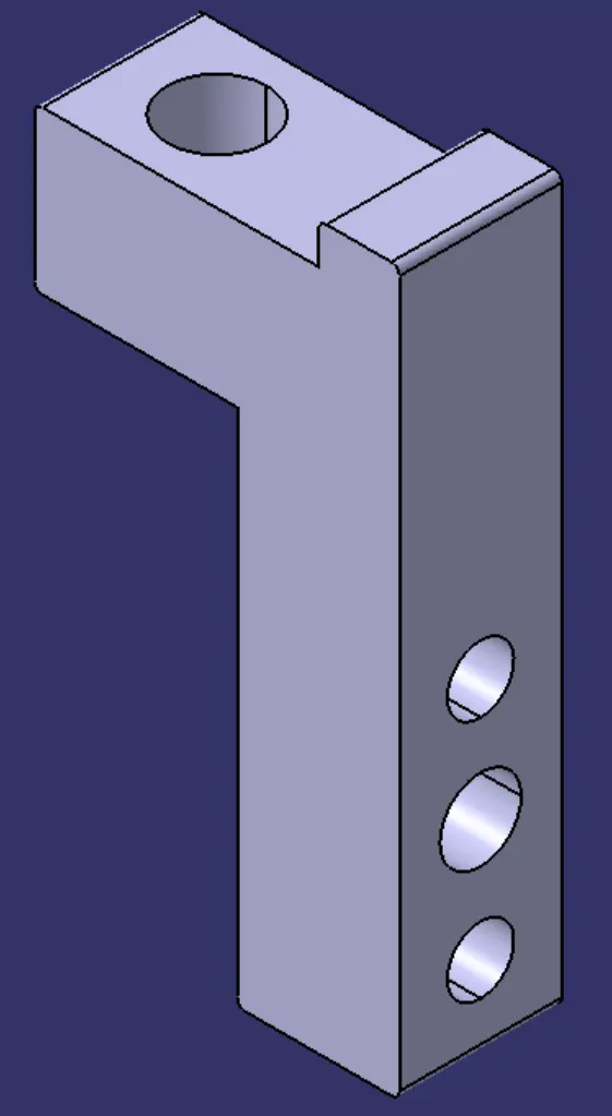
Fig 28:- Pin retainer
L- Block: A L-shaped plate is called a Block or L block. This part is used as a connection between the Pin retainer and Blade. Generally, blocks are used to provide shimming. It is not necessary that blocks are only used for shimming, its uses change as per the requirements, At some places, it is used just to connect one part to another.
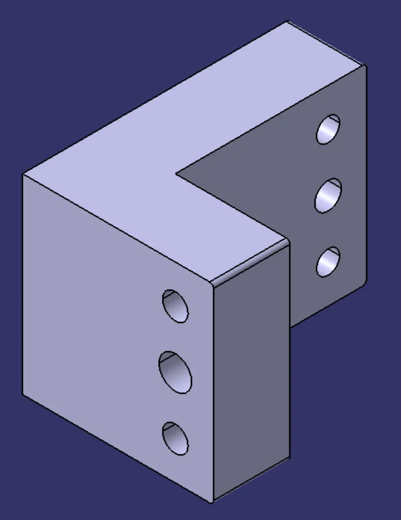
Fig 29:- L-Block
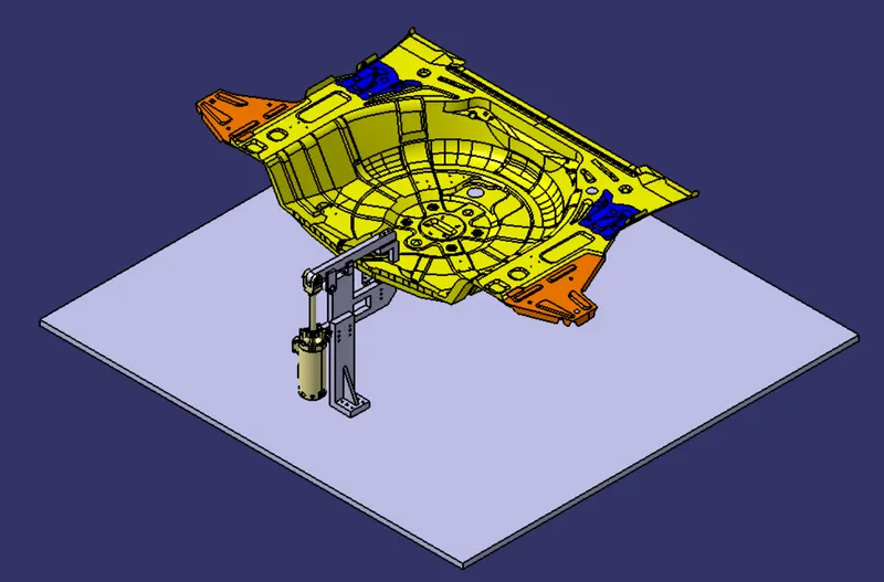
Fig 30:- Pin-clamp unit with panel (view-2)
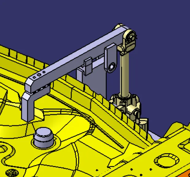
Fig 31:- Pin-clamp unit with panel (view-2)
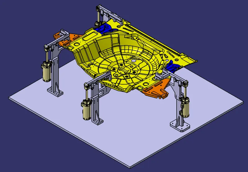
Fig 32:- Panel with Swivel Clamp Units & Pin-clamp unit (view-1)
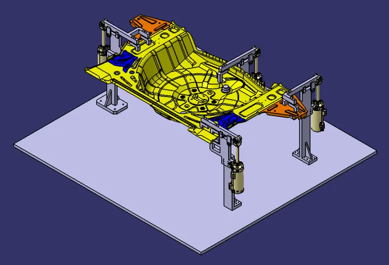
Fig 33:- Panel with Swivel Clamp Units & Pin-clamp unit (view-2)
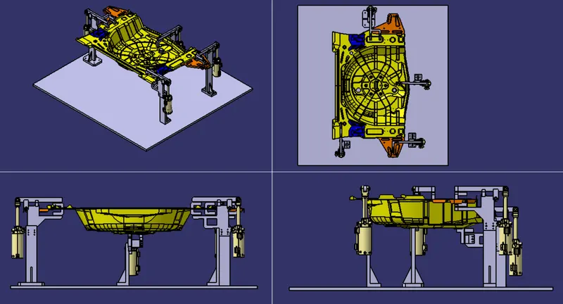
Fig 34:- Panel with Swivel Clamp Units & Pin-clamp unit (all view)
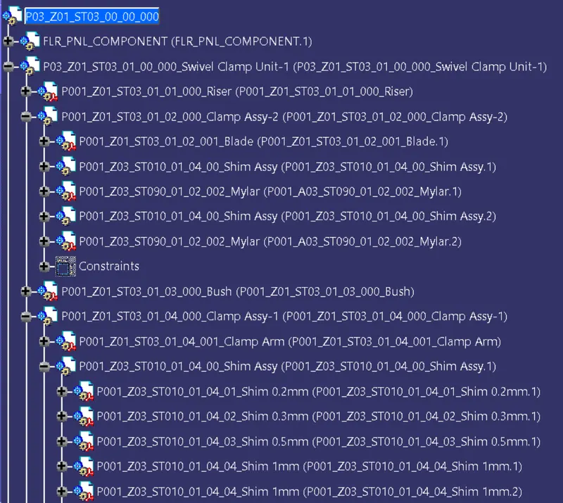
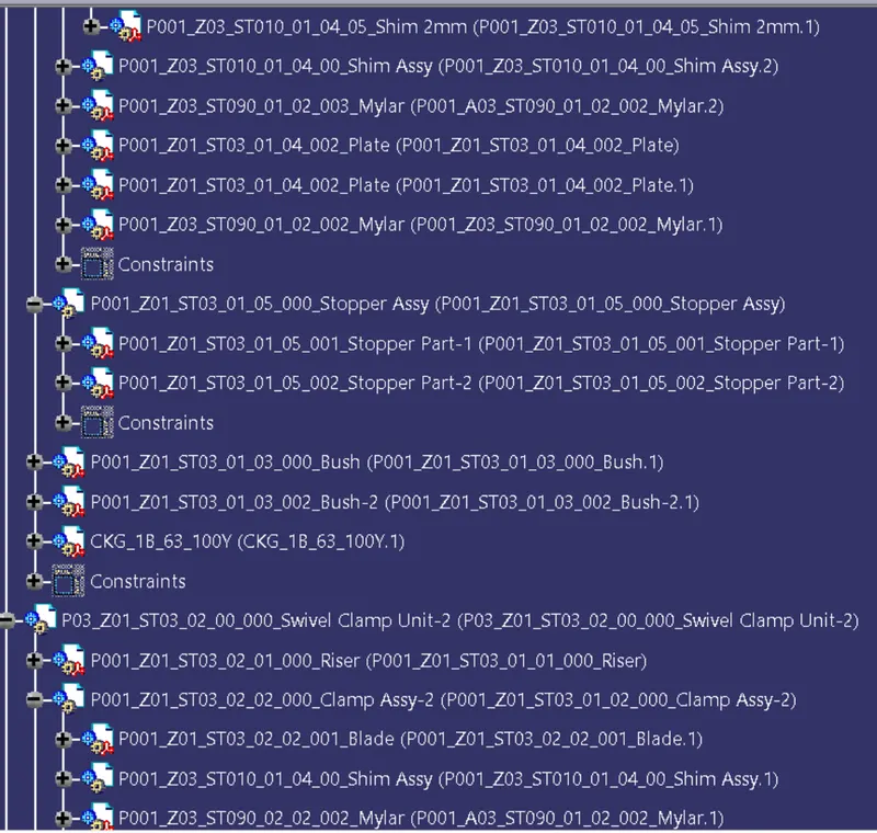
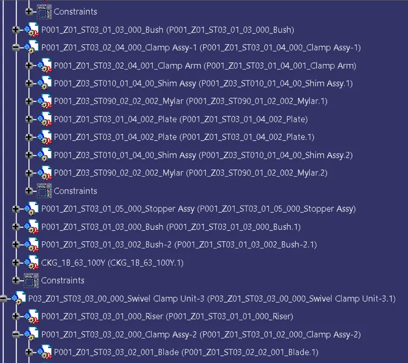
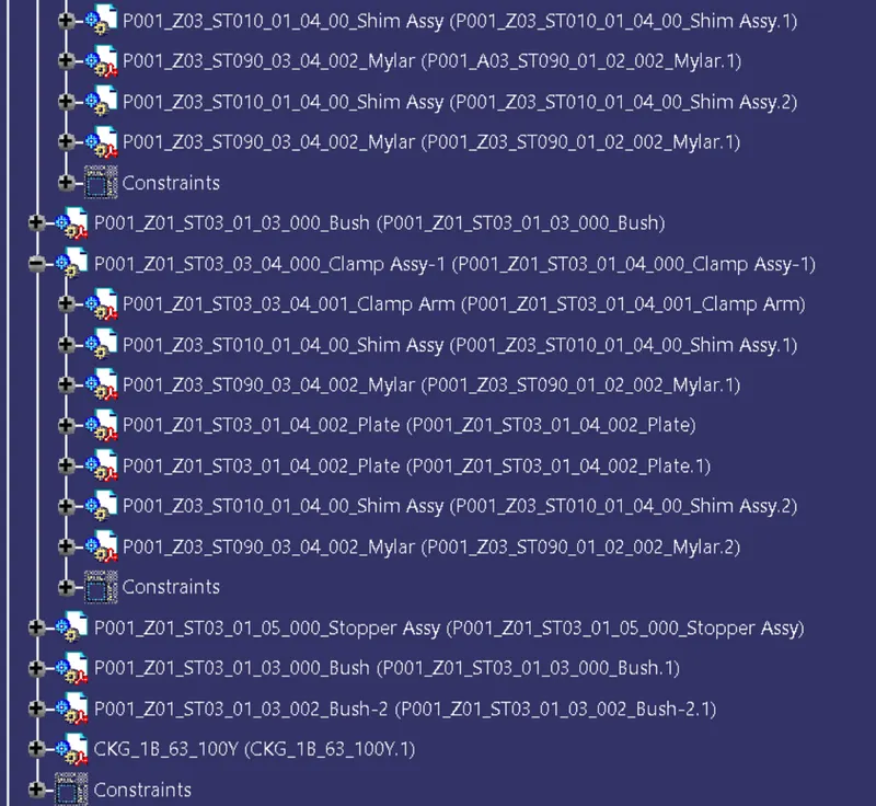
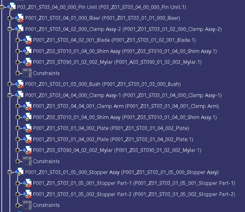
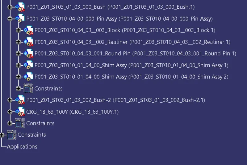
Design Tree
CONCLUSION:
3 types of Swivel Clamp Units & 1 type of Pin-clamp unit were designed & properly positioned.