Week 6:- Clamp Unit & Pin-Clamp Unit Design Challenge
Week 6:- Clamp Unit & Pin-Clamp Unit Design Challenge
AIM/INTRODUCTION/OBJECTIVE:
In this challenge, we have to design 3 different types of swivel clamp with different riser, clamp, blade, and clamp arms for the car panel & design a pin-clamp unit also considering panel thickness as 1 mm.
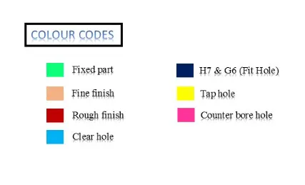
COLOUR CODE USED IN BIW FIXTURE:
REPORT & THEORY:
3-2-1 principle achievement:
The 3-2-1 principle is the basis of any fixture design. Holding fixtures used in assembly operations often follow a 3-2-1 locating scheme to position parts. Under this scheme, three locators position a part in a primary plane or direction (e.g., high/low).
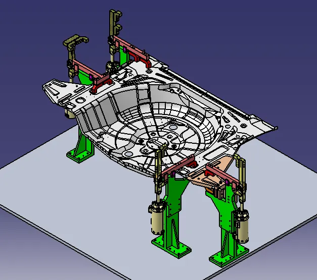
(3) Minimum: Three locator blocks to establish the part plane. Three locators or supports are placed under the workpiece. Three locators are usually positioned at primary locating surfaces. This restricts two translation motions i.e. upward & downward &four rotational motions (i.e. clockwise or anticlockwise). Together three locators with clamps restrict six degrees of freedom. The below figure shows how (3) minimum in the 3-2-1 locating scheme is achieved by clamping & resting.
(2) Round locating pin in a round hole that defines the location in four directions (4 ways) perpendicular to the plane previously established. This restricts four axial movements.
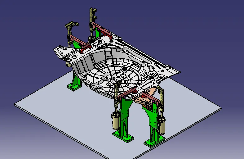
The four Swivel clamp units restrict four rotational motions & two translation motions as shown in the below figure. With the use of a pin unit, we restrict four translation motions. Together we restrict 10 degrees of freedom.
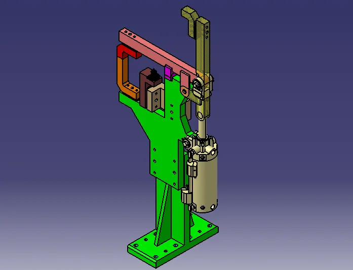
Clamp unit: Clamp unit is a unit designed to clamp / hols the car panel with NC blocks/ mylar/rest by using a pneumatic clamp cylinder & below are different parts of a clamp unit in general. Usually clamp open position is 90 degrees. Fingers are attached to clamp mylar. In the clamp unit shim to one side is enough because it will restrict translation motion in upward & downward directions only. There is another type of clamp unit known as the swivel type. There is a pivot pin around which the clamp arm rotates.
Factors should be considered while designing a clamp unit:
- there should be adequate space between the cylinder & other parts like the riser, and car panel because the cylinder moves or swings while opening & closing
- Pin clamp unit used where two panels or components are located for welding.
- Clamping make in such a way that it clamps two-car panels at once
- All parts should snap & butt properly to each other.
- Make sure that parts of the clamping unit are 10 to 12 mm away from the car panel so they do not damage the car panel
- Avoid any clash. It will not issue at assembly.
Below are the general parts of the Swivel clamp unit.
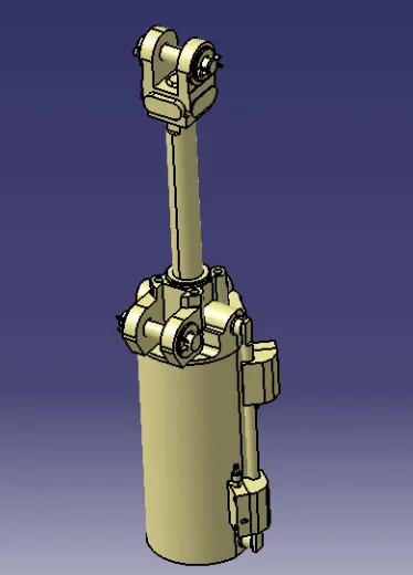
(a) Clamp Cylinder:
Cylinder designation: In this unit, we used a Clevis cylinder for clamping designated as CKG_1B_63_100Y
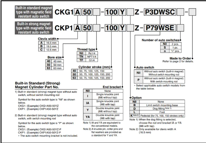
Nomenclature of the cylinder as below:
CKG1: Series of cylinder
B: Clevis width as 19.5mm.
63: Bore size
100: Stroke of cylinder
Y: End bracket i.e. double knuckle joint (M6 without tap)
(b) Clamp arm: It is the part to which clamp mylar is mounted & also clamp cylinder is attached to the end of the arm with the use of a clevis pin. It has two plates of 8 mm thickness welded & helps in rotating of clamp arm about pivoting point of the blade.
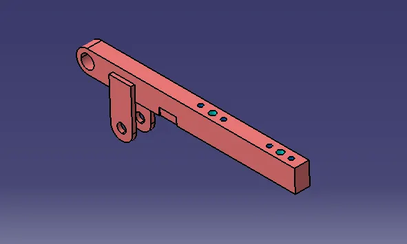
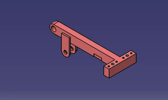
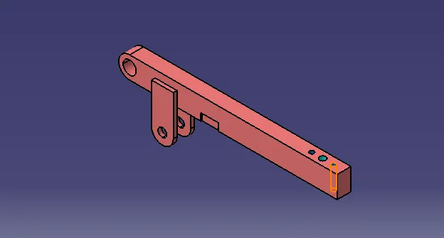
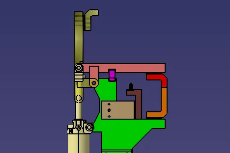
- The distance between the cylinder rod hole & pivoting hole should be 50 mm as shown in the figure. this is necessary because a stroke of 100 mm must be achieved when it is at a 90-degree open position & clamp arm mounting hole must be in line with the cylinder rod axis as shown below figure.
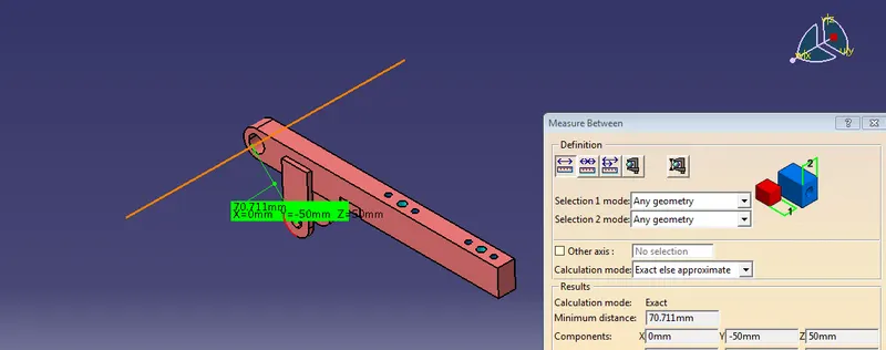
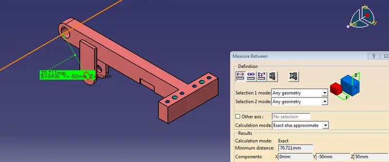
The below figure shows a 100 mm stroke achieved & clamp arm end in line with the cylinder rod. See Y & Z values.
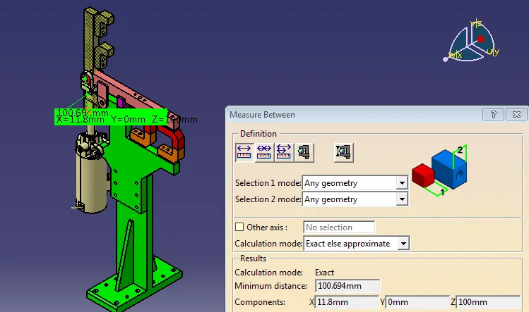
- Shape edges must be removed. Chamfer or fillet is always provided for aesthetic & safety purposes.
c) Mylar/NC blocks/Fingers: These parts are used to hold panels. They are globally called Mylar. The top side of Mylar is called clamping Mylar & bottom side is called resting Mylar. Every clamping Mylar should have resting Mylar. It is jaw type. It prevents the panel from deforming while welding. It is increase its wear strength. Following considering should be taken into account while designing Mylar.
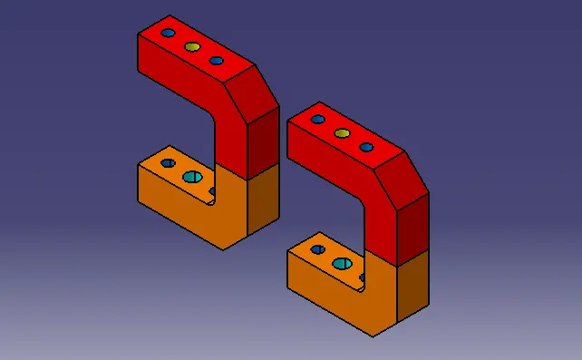
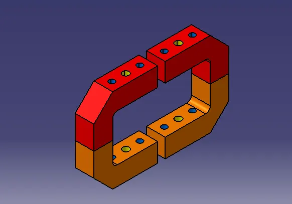
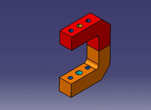
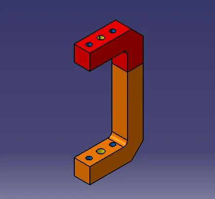
- The clamp & rest has the same size. It has a standard size of 20mm x 20mm. It has a flat surface or sometimes its profile follows the contour of the car panel. As described in the below figures.
- Clamp & rest mylar has two holes of dia.6 & one M8 tapping hole. Also, the clamp mylar has the same mounting hole pattern as like clamp arm. Also, the minimum center distance between holes should be 15mm. & reference dimension should be 8 or 10 mm.
d) Stopper:
The function of the stopper is to restrict the motion of the clamp arm. It avoids clamping the arm to rotate beyond the limit. It has two parts male & female.

e) Blade: Blade is part to which all other units are attached e.g. mylar, stopper, clamp, riser. The blade is designed according to the position of all other parts.
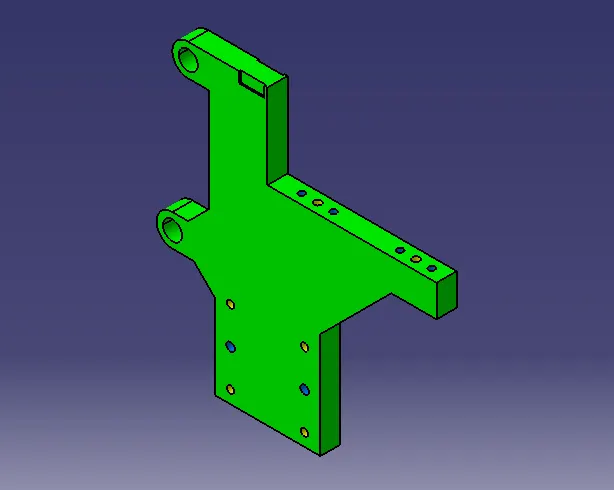
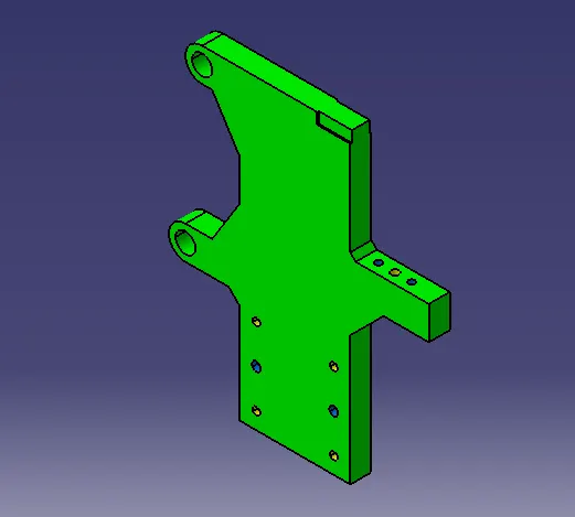
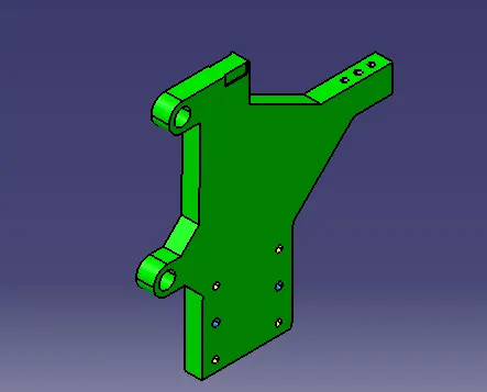
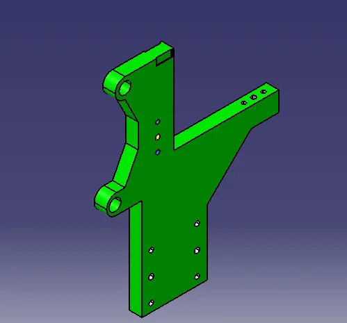
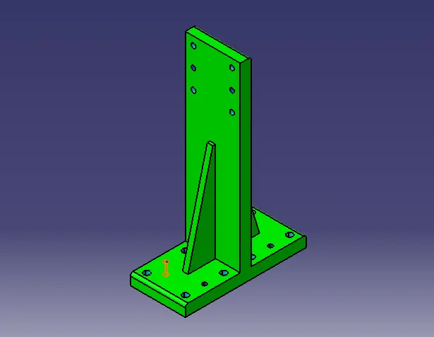
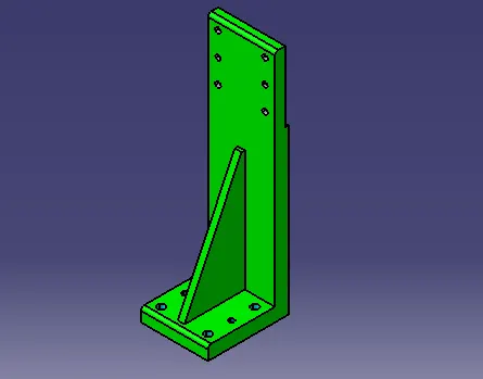
f) Riser: Riser can be of L-type, welded or square tube, or frame type. These are basically manufactured parts that are used to give height to assembly. It is machined at mounted ends only to save cost.
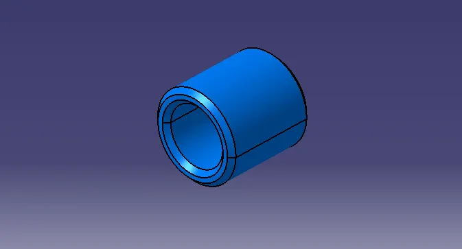
g) Bush: Bush is a friction-type bearing. It is lubricated with grease and oil. It permits relative motion between two mating parts. It is made of hard material also its ID & OD are precisely machined or ground. It press-fitted & after worn out it is replaced with a new one instead of replacing another part which saves cost. Mostly phosphor bronze or gunmetal material is used for making bush. In this unit, three bushes are used of the same internal (12mm) & external diameter (18 mm) but different lengths.
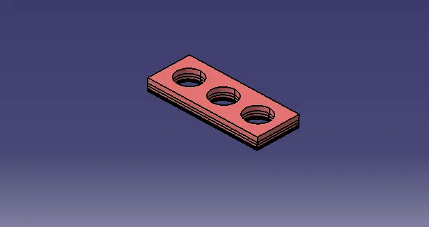
h) Shims/Spacer: In fixtures, we are providing tolerance to each part mostly manufactured. Those tolerances tend to stack up & reflect together. In order to avoid that we use shims so we can easily adjust after assembly so whatever stack up there we will rectify it through shims. Shims come in thickness of 0.1, 0.2, 0.5,1 etc.
We provide shim to accommodate clamp as well as rest mylar in two directions. Clamp & rest mylar can be adjusted in one direction only i.e. up or down. Also, the two-way shim is provided for locating the pin to accommodate adjustment.
i) Hardware: These are standard parts. Parts are assembled together with help of a washer and bolt. for better assembly should use two dowels and dour bolts for the riser and blade. Where for bolting one part should have a tapping hole and on another part a simple hole (1 to 2 mm larger from bolt size.)
The length of the bolt is decided by the width of part + (1.5*D)
For ex. where
L=Length of bolt
D=diameter of the bolt to be used
Let's take M8 Bolt
L=25 + (1.5 * 8)
L=25+12
L=37 mm.
But the length of the 37mm bolt is not available so we have to select a 40mm Bolt. (Additional 2 to 3 for washers).
Similarly, the minimum engagement length for M5, M6, M10, & M12 must be 7.5, 9, 15, and 18 mm respectively.
- j) Dowel Pins: These are standard parts. There are various types of dowel pin-like split, parallel, taper, clevis, and spring, grooved Dowel pins are used to locate parts precisely & to restrict movements. For Mylar dia. 6 or 8 dowel pins should be used for the blade, and shimming block dia. 8dowel pin should be used & for riser base dia. 10 or 12 pins are used.
- k) Washer: Standard steel grade A plain normal series washer used.
Below are three designed swivel clamp units & one pin clamp unit:
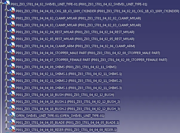
1. Below unit is named P001_Z03_ST01_04_02_SWIVEL_UNIT_TYPE-01 & is designed with a clevis clamp cylinder
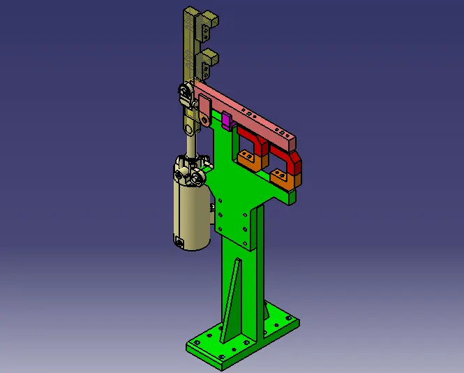
Below fig shows the clamping of the car panel & also the retracted position of the clamp arm at 90 degrees.
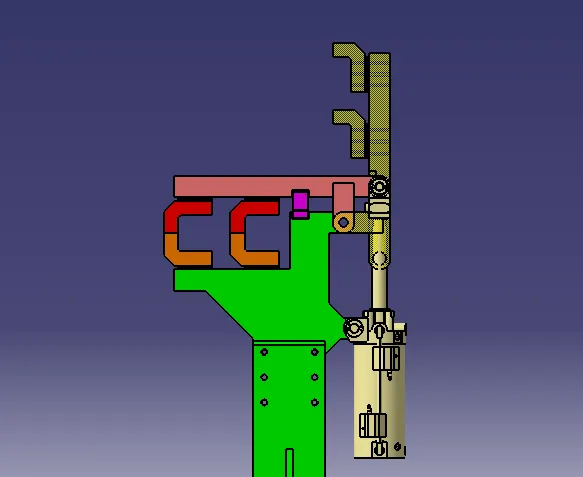
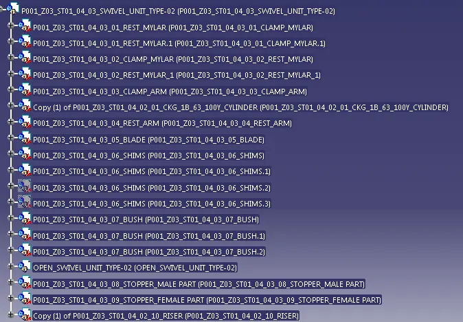
2. Below unit is named P001_Z03_ST01_04_03_SWIVEL_UNIT_TYPE-02 & is designed with a clevis clamp cylinder
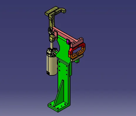
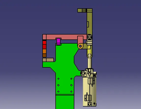
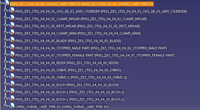
3. Below unit is named P001_Z03_ST01_04_04_SWIVEL_UNIT_TYPE-03 & is designed with a clevis clamp cylinder
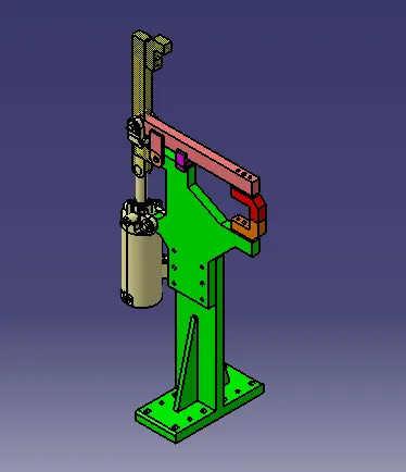
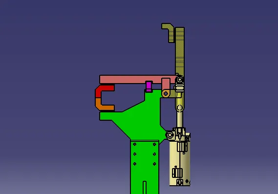
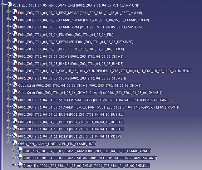
4. Below unit is named P001_Z03_ST01_04_05_PIN_CLAMP_UNIT & is designed with a clevis clamp cylinder
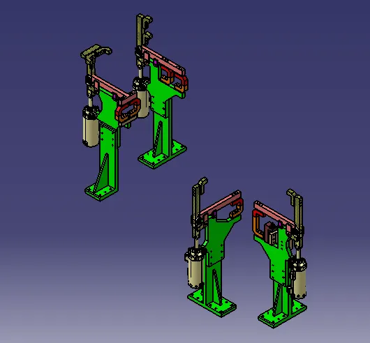
Below figures show all clamp units with the car panel
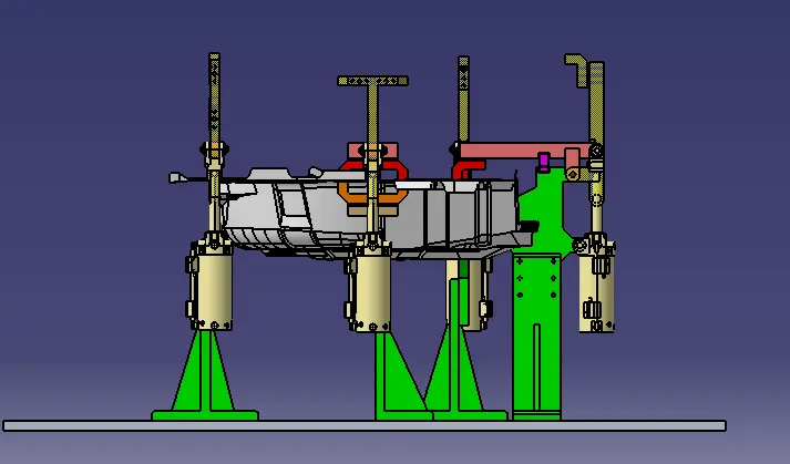
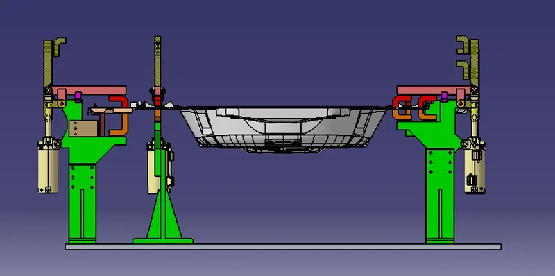
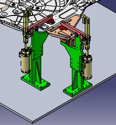
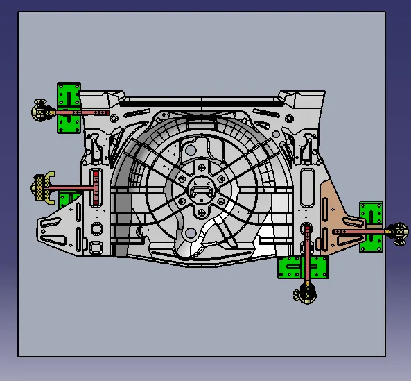
Clamp plan: It provides information about the position of the clamp unit, pin unit, rest unit, dump unit, etc. This is major input from customers & it should be never changed without the permission of the customer. The clamp plan provided the exact location of pins, rest, clamp, etc. It is in more detail. It gives the exact location in X, Y & Z coordinates value to start designing.
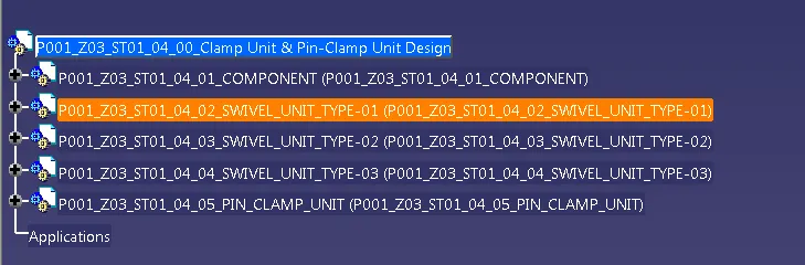
Structuring a design tree:
thanku