CHT Analysis on a Graphics card
Aim –
- To perform a steady-state conjugate heat transfer analysis on a model of a graphic card.
- To run the simulation for best possible mesh with the combination of coarse and refined mesh quality in different region.
Objective –
- Run the simulation by varying the velocity from 1m/sec to 5 m/sec for at least 3 velocities and discuss the results.
- Find out the maximum temperature and heat transfer coefficient attained by processor.
- Prove that the simulation has attained convergence with appropriate images and plots.
Conjugate Heat transfer –
- This type of analysis allows the simulation of heat transfer between solid and fluid boundaries by exchanging thermal energy at the interfaces between them.
- CHT analysis has an advantage over the FE thermal analysis in calculating the wall heat transfer coefficient. It is calculated directly rather than solving empirical equations.
- CHT analysis is used to correctly predict the surface temperature and heat exchanging capabilities of engineering devices.
Theory –
Brief about CHT –
Conjugate heat transfer corresponds with the combination of heat transfer in solids and heat transfer in fluids. In solids, conduction often dominates whereas, in fluids, convection usually dominates. Efficiently combining heat transfer in fluids and solids is the key to designing effective coolers, heaters, or heat exchangers. Forced convection is the most common way to achieve a heat transfer rate. In some applications, the performances are further improved by combining convection with phase change (for example liquid water to vapor phase change).
The CHT approach has an advantage over FE thermal Analysis in that wall heat transfer coefficients and their local variations on surface are directly calculated within the model rather than based on simplified empirical calculations. The CHT approach, therefore, has benefit for those application where heat transfer is either non-uniform or difficult to calculate empirically.
Typical design problems involve the determination of:
- Overall heat transfer coefficient, e.g. for a car radiator.
- The highest (or lowest) temperature in a system, e.g. in a gas turbine, chemical reaction vessels, food ovens.
- Temperature distribution (related to thermal stress), e.g. in the walls of a spacecraft
- Temperature response in time-dependent heating/cooling problems, e.g. engine cooling, or how fast does a car heat up in the sun and how it is affected by the shape of the windshield.
Benefits:
- Effective heat transfer
- Energy savings
- Interaction between solid and fluid bodies.
Applications:
- Heat exchangers
- Electronic equipment like graphic cards, motherboards, etc.
- General heating and cooling systems.
- Exhaust ports.
Inlet :-Velocity of air=5m/s
Temperature = 300K
Graphic Card
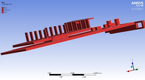
The main components of graphic cards are:
- Processor
- Fins
- Base
Processor
A GPU (graphics processing unit) is designed specifically for performing the complex mathematical and geometric calculations that are necessary for graphic rendering. Some of the fastest GPUs have more transistors than the average CPU. A GPU produces a lot of heat, so it is usually located under a heat sink or a fan.
Fins
Fins act as a passive heat exchanger that transfers the heat generated by an electronic or a mechanical device to a fluid medium, often air or a liquid coolant, where it is dissipated away from the device, thereby allowing regulation of the device temperature at optimal levels.
Aluminum alloys are the most common heat sink materials. This is because of aluminum cost lesser than copper. However, copper is used where higher levels of thermal conductivity are needed. Some hear sink use a combination of aluminum fins with copper base.
Base
The base is defined as a part on which various component is attached. The base is the part where processor, fins and other connections are connected to it.
Procedure –
Geometry preparation:
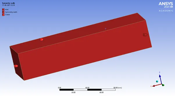
Import the geometry in Space-claim. Check for any edges in interference so that conformal mesh can be achieved. The below model is enclosed in an enclosure.
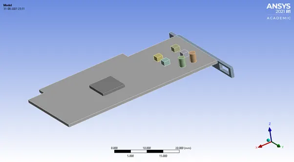
Using share topology, select all the components viz the PCB, processor, fins and enclosure are shared together so as to get conformal mesh. The conformality of mesh is very important to see the heat transfer effects at the surface of the solid boundary.
Mesh –
Named selection –
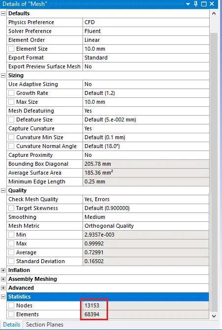
Case 1 – Baseline Mesh
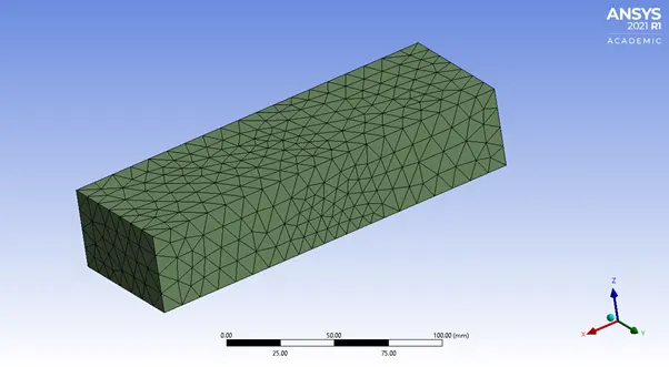
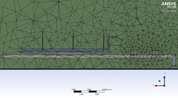
Mesh Details -
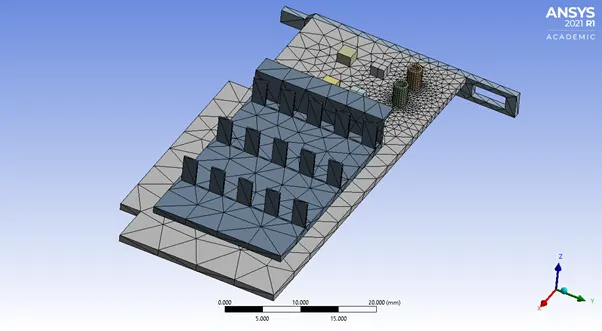
Mesh Quality –
Element quality:
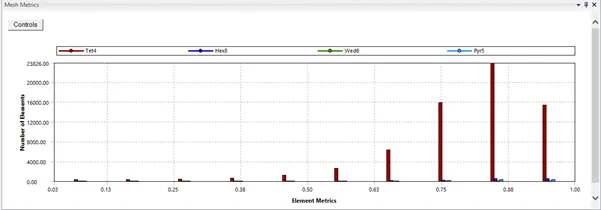
Skewness:
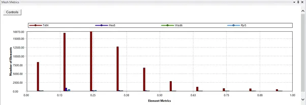
Orthogonal quality:
Case 2 – Refined Mesh –
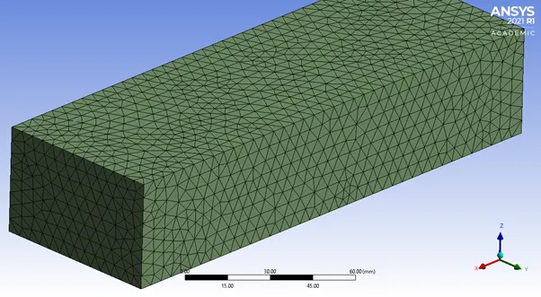
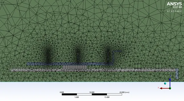
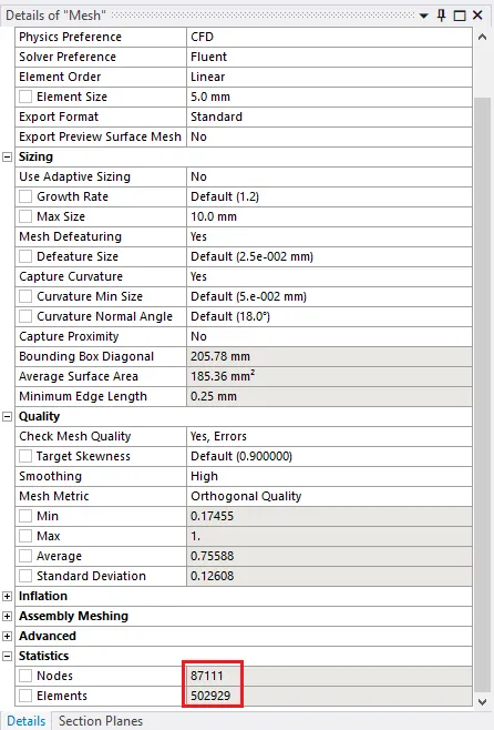
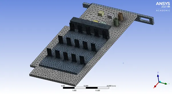
Mesh details –
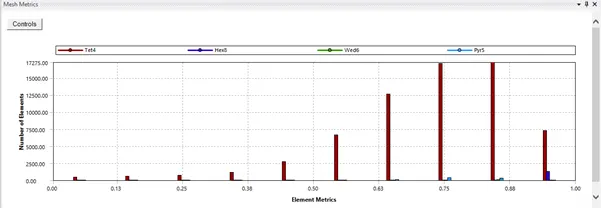
Mesh Quality –
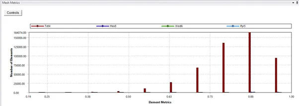
Element quality:
Skewness:
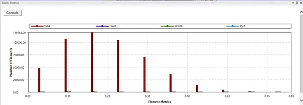
Orthogonal quality:
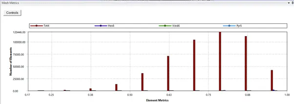
The above mesh setting was chosen because we have limit on the cell count in academic license and hence forth, we couldn’t refine the mesh further in all region. Therefore, region such as the processor, fins and base were refined according to the requirement.
Solution Setup -
- General → Solver → Pressure-based → Time→ Steady State
- Models → Viscous → K-epsilon → Realizable → Enhanced wall function
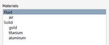
- Materials →
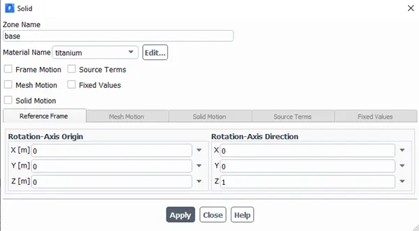
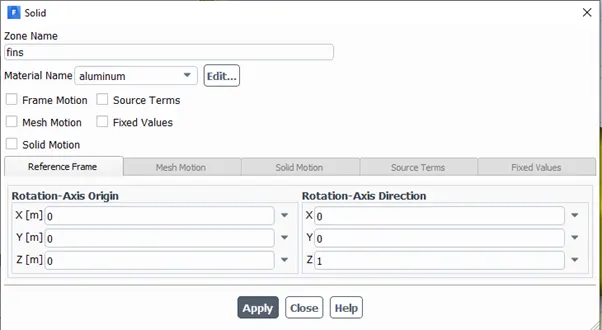
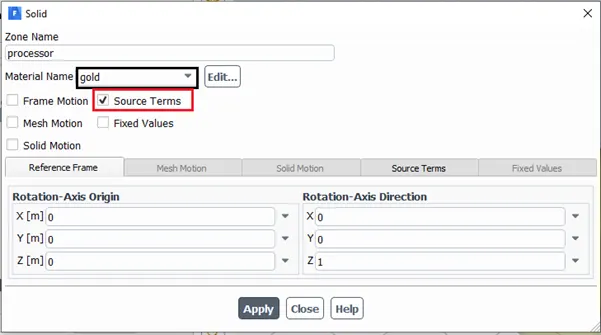
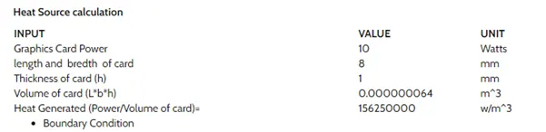
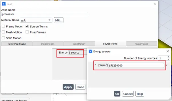
- Cell Zone Conditions → fff_surface →
---------------------------------------------------------------------------------------------------
- Boundary Conditions
- Intel (Velocity= User-defined)
- Outlet (Gauss Pressure=1 atm)
- Symmetry_walls → Wall Motion → Stationary → Shear Condition → No Slip
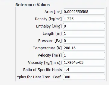
- Reference Values →
- Method →
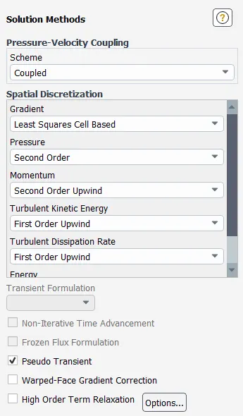
- Results → Create → Plane→ ZX-plane
- Solution → Definition →
- Surface Report → Maximum Temperature → Temperature/Total Temperature → Field Variable = processor
- Initialize Solution → Hybrid
- Results →
- Create Contour → Velocity → Field Variable = All Named Selections
- Create Contour → Total Temperature → Field Variable = All Named Selections
- Activities → Create Animation → Solution Animation → Velocity Contour
Results -
Baseline -
Velocity = 1 m/s
No of Time Step =600
Time Step = 1 second
Hybrid Initialization
-------------------------------------------
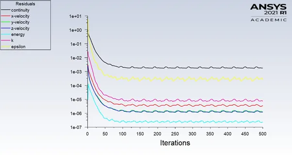
Scaled Residual Plot –
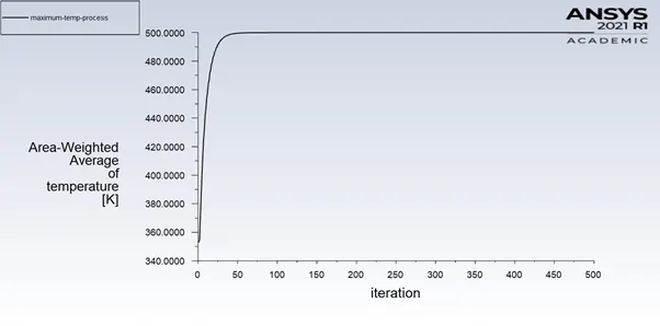
Maximum Temperature at Processor –
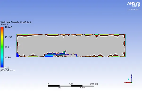
HTC –
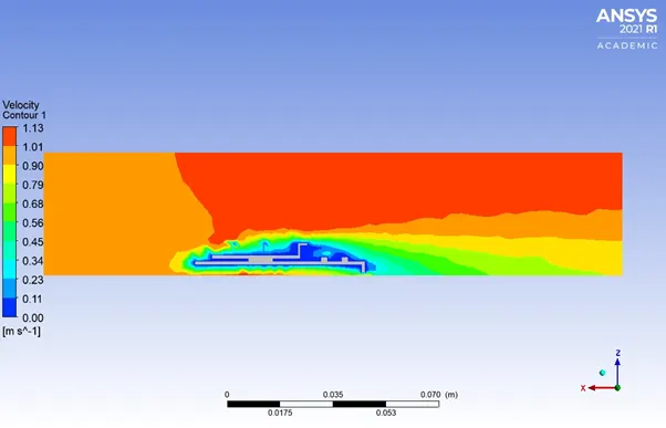
Velocity contour through Graphic Card –
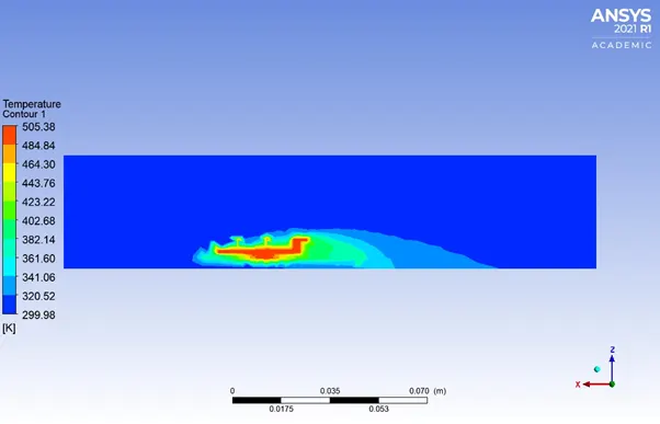
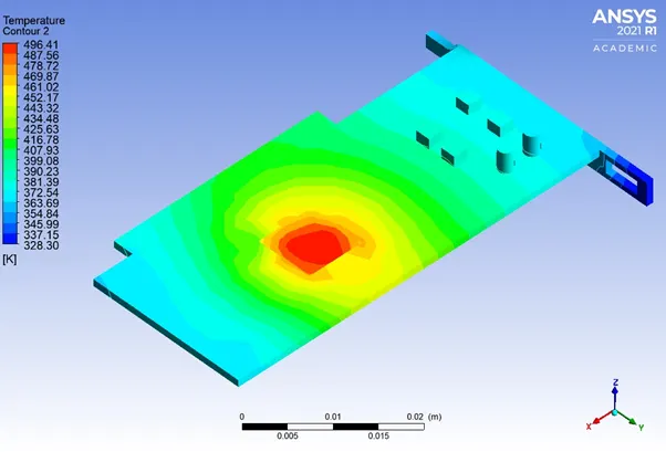
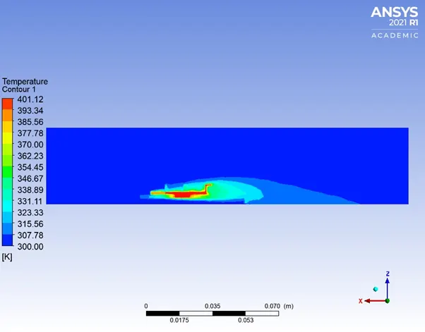
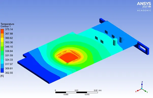
Temperature contour through Graphic Card –
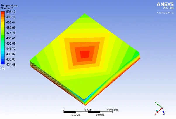
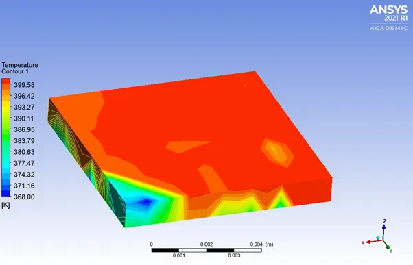
Potential Hotspot –
Processor:
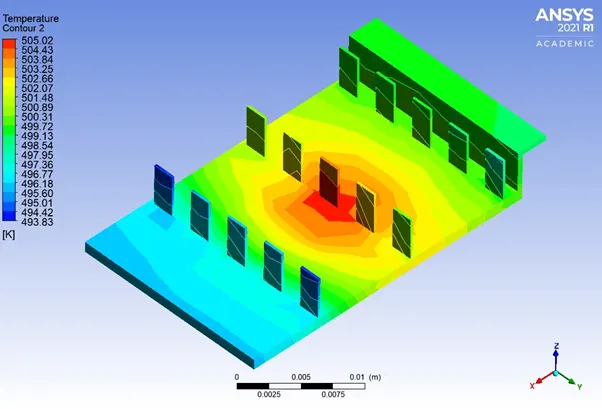
Fins:
Base:
Refined Mesh –
R-case-1
Velocity = 3 m/s
No of Time Step =600
Time Step = 1 second
Hybrid Initialization
-------------------------------------------
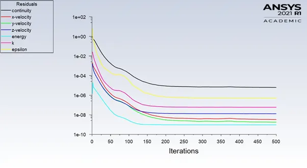
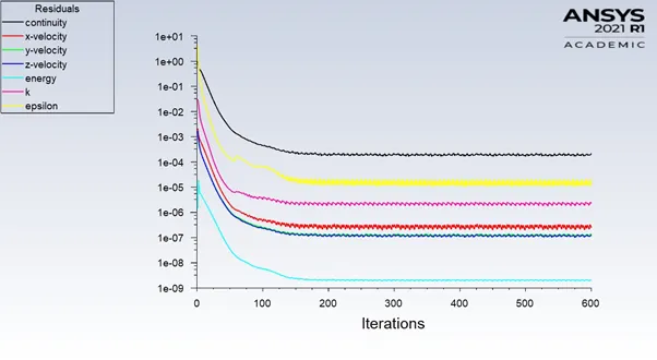
Scaled Residual Plot –
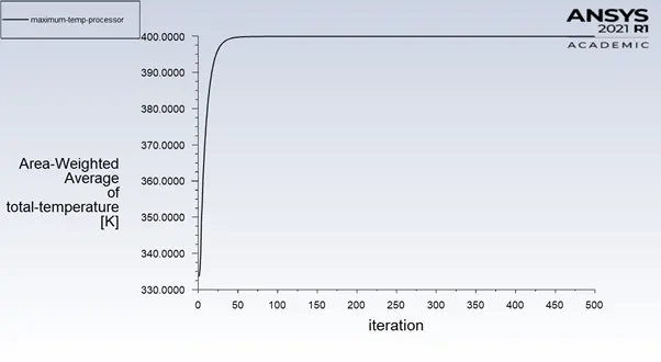
Maximum Temperature at Processor –
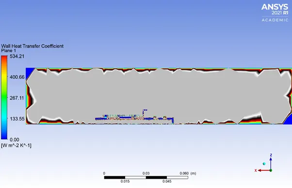
HTC –
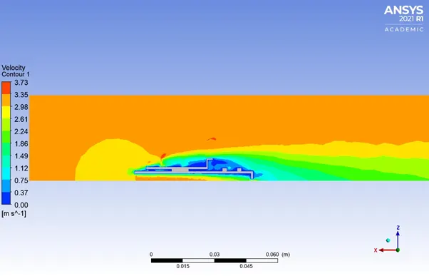
Velocity contour through Graphic Card –
Temperature contour through Graphic Card –
Potential Hotspot –
Processor:
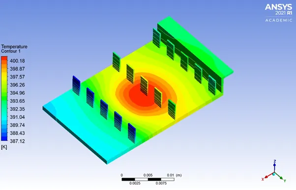
Fins:
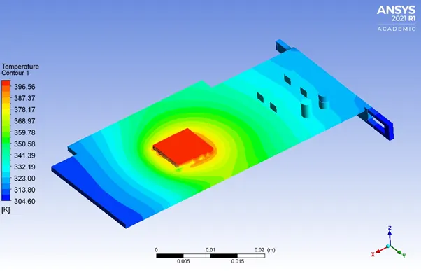
Processor and Base:
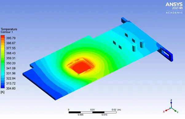
Base:
R-case-2
Velocity = 5 m/s
No of Time Step =600
Time Step = 1 second
Hybrid Initialization
-----------------------------
Scaled Residual Plot –
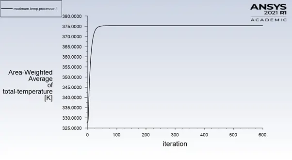
Maximum Temperature at Processor –
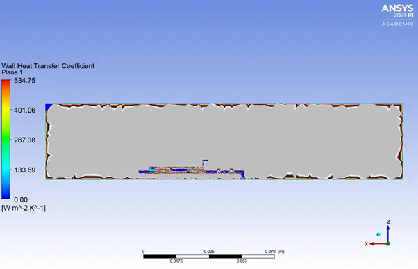
HTC –
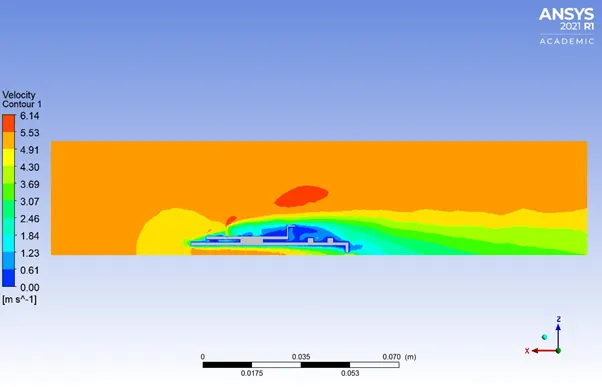
Velocity contour through Graphic Card –
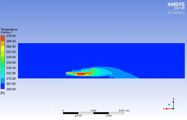
Temperature contour through Graphic Card –
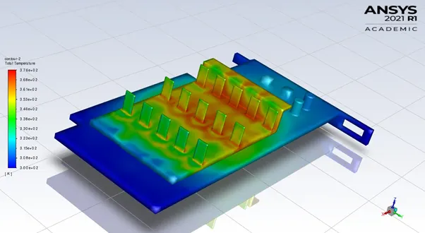
Potential Hotspot –
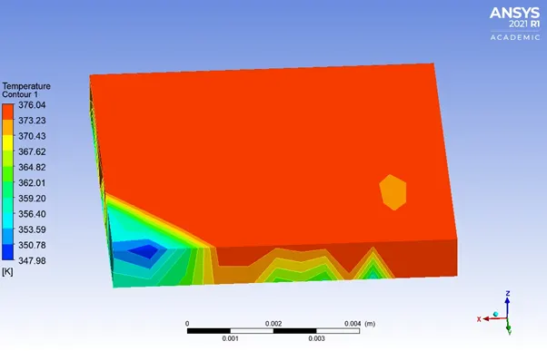
Processor:
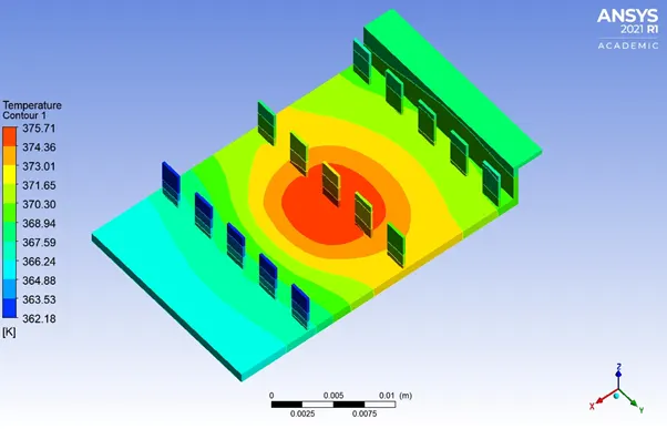
Fins:
Processor & Base:
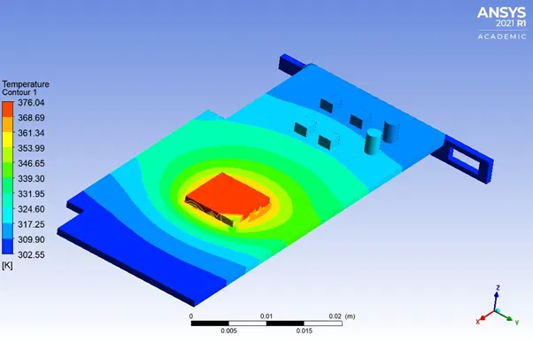
Base:
Inference –
|
SL |
Velocity (m/sec) |
Maximum Temperature (K) |
HTC at Fin (W/m^2*K^-1) |
|
1 |
1 (Coarse) |
505.02 |
175.42 |
|
2 |
3 (Fine) |
400 |
534,21 |
|
3 |
5 (Fine) |
375 |
534.75 |
Convergence criterion to keep in check and its effects
Residual –
- The solution can be considered as converge as the change in gradients of residuals is very small and follows a pattern after 92 iterations for baseline setup and 150 iterations for refined setup.
Velocity effect on Temperature –
- With an increase in velocity, the temperature 505.02 K @ 1m/sec to 375 K @ 5 m/sec.
- Maximum temperature attained in the component is inversely proportional to inlet fluid velocity.
- With increase in fluid velocity, heat removal by convection is quicker and less temperature is attained.
Velocity effect on Wall HTC –
- With an increase in velocity, user can observe a substantial rise in the heat transfer coefficient.
- This in-turns proves that high-velocity cooling air can be effective mode for heat dissipation.
Total Temperature –
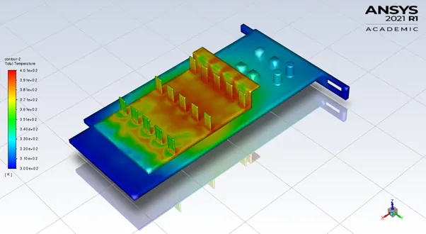
- High temperature is attained by fin and base near the surface in-contact with processor.
- We can foresee from the above plots; the hot spot region is formed in the processor (Energy source) which in-turn is connected to base and fins.
- Heat transfer starts with conduction at the contact region between the processor – fins and processor – base.
- Next phase of heat transfer occurs in-form of convection through the inlet airflow.
Effect on Mesh Size –
- Fine mesh results in higher heat transfer coefficient compared to coarse mesh this is due to refinement of mesh done at fins and base of the fins & base of graphic card for better computation of wall heat transfer coefficient at fins and base.
- Finer the mesh more accurate the temperature distribution obtained.
Conclusion –
A steady-state CHT analysis of graphic card model was performed by varying the inlet fluid velocities and mesh size. Following observations are made based on the contours –
- Refined mesh produces more accurate result when compared to coarse mesh.
- The time to converge increase exponentially.
- The temperature of processor and fins reduce as the velocity of the air increases.
- This indicates that as airflow increases, the rate of heat transfer increases. Hence, the cooling rate of graphic card also increases.
- The potential hotspot in this simulation investigation is the heat source – processor.
- Apart from that, the airflow is very low in the lower portion of the base.
- Also, there are no fins provided at that location. This creates a potential hotspot and needs to be resolved.