Week 6 - CHT Analysis on a Graphics card
AIM
CHT Analysis on a Graphics Card.
OBJECTIVE
Ansys Fluent is the industry-leading fluid simulation software known for its advanced physics modeling capabilities and industry leading accuracy.Ansys Fluent gives you more time to innovate and optimize product performance. Trust your simulation results with a software that has been extensively validated across a wide range of applications. With Ansys Fluent, you can create advanced physics models and analyze a variety of fluids phenomena—all in a customizable and intuitive space.
CONJUGATE HEAT TRANSFER
There are several challenges when solving the fluid and solid domains together. The largest challenge to overcome is the difference in time-scales associated with the heat transfer in the fluid and the solid. In general, heat transfer in the solid occurs more slowly than the convective and diffusive time-scales of the fluid. This disparity in time-scales is problematic for CFD simulations because simulations of long physical time periods can be computationally expensive.
In graphics card we see that there are a lot of cores known as cuda-cores which when under pressure generates a lot of heat. This heat if kept as is may cause the processor to destroy or burn the board. So we need to introduce a fan to extract and remove the ehat from the system. In this project we will simulate the flow of heat and the conduction rate for different velocity of air flowing at 295K.
WHAT IS A GRAPHICS CARD?
A graphics card is a type of display adapter or video card installed within most computing devices to display graphical data with high clarity, color, definition and overall appearance. A graphics card provides high-quality visual display by processing and executing graphical data using advanced graphical techniques, features and functions.
A graphics card is also known as a graphics adapter, graphics controller, graphics accelerator card or graphics board.
A graphics card is primarily designed to remove the graphical processing tasks from the processor or RAM. It includes a dedicated graphical processing unit (GPU) and a dedicated RAM that help it to process graphical data quickly. Like most processors, a graphics card also has a dedicated heat sink to keep the heat out of the GPU. A graphics card enables the display of 3-D images, image rasterization, higher pixel ration, a broader range of colors and more. Moreover, a graphics card includes various expansion ports such as AGP, HDMI, TV and multiple monitor connectivity. A graphics card can be integrated within the motherboard or be added on as an extension card.
STEPS TO FOLLOW FOR MODELLING AND DEVELOPING MESH FOLLOWED BY PREPROCESSING ARE GIVEN BELOW.
THE STEPS ARE AS FOLLOWS.
STEP 1- FIRST WE NEED TO OPEN SPACE CLAIM
STEP 2- THEN WE NEED TO IMPORT THE EXHAUST PORT STEP FILE INTO THE SYSTEM WHICH WILL GENERATE THE BODY.
STEP 3- NOW WE HAVE TO USE THE REPAIR EDGE TOOL TO REPAIR ANY DUPLICATE EDGES.
STEP 4- NOW WE GO TO PREPARE RIBBON AND CREATE THE ENCLOSURE.
STEP 5- NAME THE VOLUMES AS FLUID VOLUMES AND SOLID VOLUMES. AND THEN CLOSE THE INTERPHASE.
STEP 6- NOW OPEN MESHING.IN MESHING WE GIVE A MESH SIZE STANDARD OF 0.85 mm AND GENERATE THE MESH. WE ADD A BODY SIZING PARAMETER TO 0.5 MM FOR THE REFINEMENT OF THE PROCESSOR.
STEP 7-THEN WE WILL SEE THAT THE SOLID AND FLUID INTERPHASE ARE NOT HAVING EXACT SAME NOD POINTS WHICH WILL RESULT IN WRONG SIMULATION AS THE HEAT TRANSFER WILL NOT TAKE PLACE.
STEP 8- SO WE WILL HAVE TO GO BACK IN SPACE CLAIM AND WE HAVE TO TURN ON SHARE TOPOLOGY.
STEP 9- NOW WE HAVE TO MAKE THE NAMES SELECTION FOR 1 INLET ,1 OUTLET, WALLS,BASE, PROCESORS AND FINS.
STEP 10- DOULBLE CLICK ON THE OUTER METAL PART AND NAME IT OUTER CONVECTION WALL.
STEP 11-NOW OPEN THE SETUP WINDOW AND LOOK FOR THE MESH WHICH WILL LOOK AS BELOW.
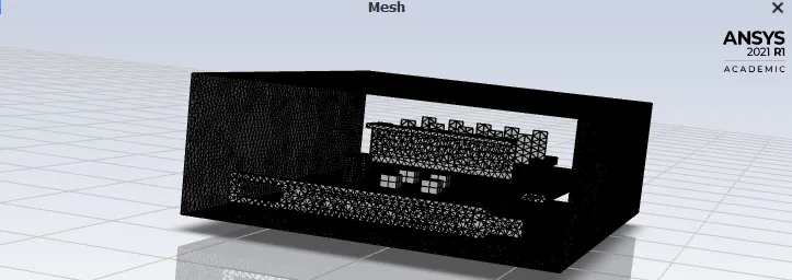
STEP 12- WE WILL USE A PRESSURE BASE SOLVER HERE WITH STEADY STATE ANALYSIS. WE WILL USE K-EPSILON TURBULANCE MODEL. THE SOLID IS ALUMINIUM FOR BASE ,COPPER FOR FINS AND PROCESSOR. THE FLUID IS AIR FOR THE TUNNEL.
STEP 13-INLET VELOCITY IS 1 m/s , 3 m/s, 5 m/s AND THE TEMPERATURE IS 295K. THIS IS SAME FOR BOTH COARSE AND FINE MESH SETUPS.
STEP 14-THE SOURCE TERM IS ADDED FOR PROCESSOR WITH AHEAT HENERATION OF 50000000W/m^3. THIS SOURCE TERM HELPS US TO ADD THE HEAT GENERATION.
STEP 15- NOW WE INITIALISE THE CASE. WE ALSO ADD CONTOUR ON TH XZ PLANE TO VISUALIZE THE TEMPERATURE. WE ALSO ADD A SOLUTION ANIMATION ON THE VISUALIZE.
STEP 16- NOW WE RUN THE CALCULATION FOR 200 ITERATIONS.
NOW LET US MAKE 1 THING CLEAR. THE COURSE MESH WAS NOT WORKING AS THE SOLUTION WAS BLOWING UP.
NOW LET US TAKE A LOOK AT THE SOLUTIONS.
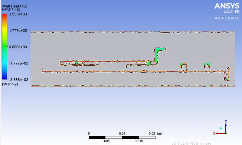
NOW LET US UNDERSTAND WHAT IS HEQTFLUX?
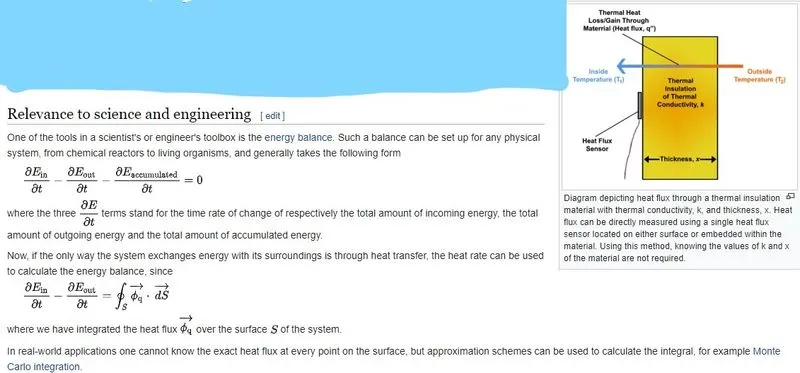
Heat flux or thermal flux, sometimes also referred to as heat flux density, heat-flow density or heat flow rate intensity is a flow of energy per unit of area per unit of time. In SI its units are watts per square metre (W⋅m −2 ). It has both a direction and a magnitude, and so it is a vector quantity.
The measurement of heat flux can be performed in a few different manners. A commonly known, but often impractical, method is performed by measuring a temperature difference over a piece of material with known thermal conductivity. This method is analogous to a standard way to measure an electric current, where one measures the voltage drop over a known resistor. Usually this method is difficult to perform since the thermal resistance of the material being tested is often not known. Accurate values for the material's thickness and thermal conductivity would be required in order to determine thermal resistance. Using the thermal resistance, along with temperature measurements on either side of the material, heat flux can then be indirectly calculated.
A second method of measuring heat flux is by using a heat flux sensor, or heat flux transducer, to directly measure the amount of heat being transferred to/from the surface that the heat flux sensor is mounted to. The most common type of heat flux sensor is a differential temperature thermopile which operates on essentially the same principle as the first measurement method that was mentioned except it has the advantage in that the thermal resistance/conductivity does not need to be a known parameter. These parameters do not have to be known since the heat flux sensor enables an in-situ measurement of the existing heat flux by using the Seebeck effect. However, differential thermopile heat flux sensors have to be calibrated in order to relate their output signals [μV] to heat flux values [W/(m2⋅K)]. Once the heat flux sensor is calibrated it can then be used to directly measure heat flux without requiring the rarely known value of thermal resistance or thermal conductivity.
NOTE:THE MESH SETUP IS IDENTICAL FOR ALL THE FOLLOWING CASES. ONLY THE VELOCITY IS VARIED BETWEEN 1m/s AND 5 m/s.
LET US SEE THE RESULTS.
CASE 1: FOR 1M/S
SCALAR RESIDUALS
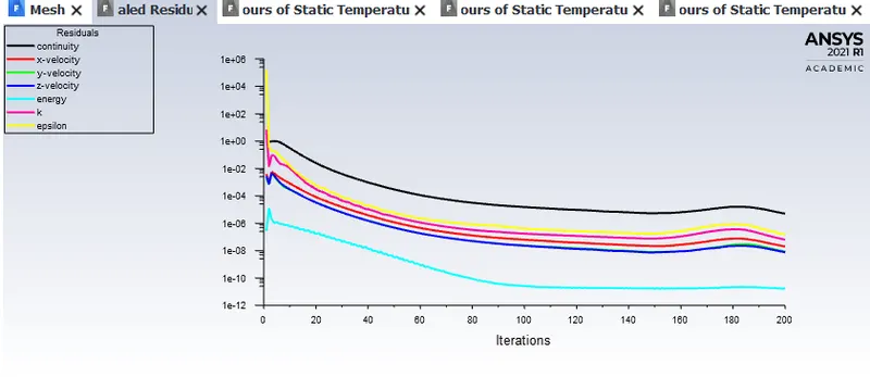
NOTE: SINCE THE GRAPHS HAVE BECOME LINEAR WE CAN SAY THAT THE SOLUTION HAVE CONVERGED.
TEMPERATURE CONTOUR OF SOLID AND FLUID ELEMENT TRANITION.
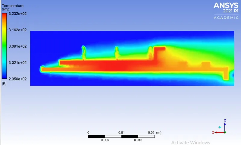
HEATFLUS ON XZ PLANE.
CASE 1: FOR 3 M/S
SCALAR RESIDUALS
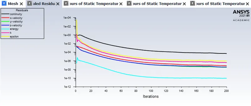
NOTE: SINCE THE GRAPHS HAVE BECOME LINEAR WE CAN SAY THAT THE SOLUTION HAVE CONVERGED.
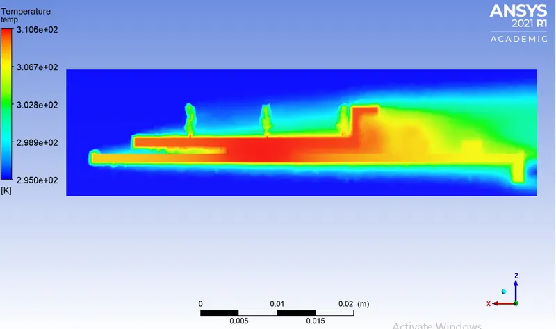
TEMPERATURE CONTOUR OF SOLID AND FLUID ELEMENT TRANITION.
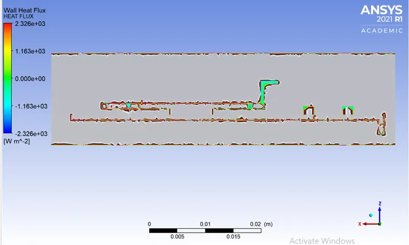
HEATFLUS ON XZ PLANE.
CASE 1: FOR 5M/S
SCALAR RESIDUALS
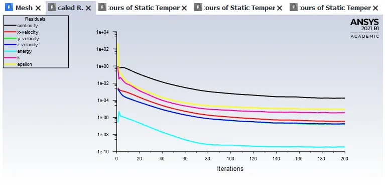
NOTE: SINCE THE GRAPHS HAVE BECOME LINEAR WE CAN SAY THAT THE SOLUTION HAVE CONVERGED.
TEMPERATURE CONTOUR OF SOLID AND FLUID ELEMENT TRANITION.
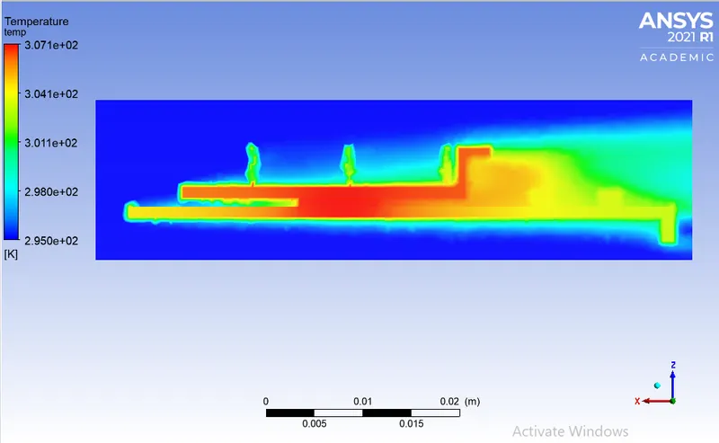
HEATFLUS ON XZ PLANE.
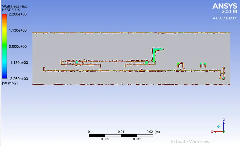
THE COMPARISON FOR THE 3 CASES ARE GIVEN BELOW.
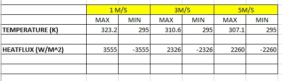
FROM THIS WE CAN DRAW SOME CONCLUSION.
1. THE VELOCITY OF THE AIR AFFECTS THE TEMPERATURE CONTOUR AND THE HEAT TRANSFER RATE.
2.INCREASE IN VELOCITY LEADS TO DECREASE IN HEATFLUX AS THE HEAT IS GETTING CARRIED AWAY FROM THE WALL.
WE SEE THE HREAT FLUX IS MINIMUM FOR 5M/S WHERE AS MAX FOR 1M/S.
3.THE POTENTIAL HOTSPOT IS THE PROCESSOR AND ALSO THE CORNERS FROM WHERE THE HEATLOSS TAKES PLACE.