Week 6 - CHT Analysis on a Graphics card
CHT analysis on a Graphic card :
Aim : To perform a Steady state Conjugate Heat transfer analysis on a Graphics card and report the simulation results.
Objectives :
1. To setup a conjugate heat transfer analysis case in ANSYS FLUENT.
2. To compute the variables like Wall Heat flux, Wall heat transfer coefficient which are the essential quantities when performing a CHT analysis.
3. Post process the results and provide valid explanations for the observed contours / plots.
Theory :
A Conjugate heat transfer is the phenomenon in which heat transfer takes place simultaneously by the modes of conduction, convection and radiation.
An important problem pertaining to the Conjugate heat transfer analysis is that of the Heat disspiation of a Graphics card by the means of forced convection.
In this case, a fan is used to force the air on to the graphics card for the faster heat dissipation. It is intuitive that the rate of heat dissipation increases with the increase in the velocity of the air.
Assumptions in solving the CHT problem :
1. The air flow is assumed to be uniform and unidirectional and irrotational.
2. The air flow is from a inlet vent. (as opposed to the general air flow through the fan installed on the top of the heat sink).
Calculations :
1. The velocity of the air from the inlet = 2 m/s
2. Reynolds number corresponding to the above velocity :
The width of the graphics card (0.019 m) is take as the characteristic length.
Re = ρ*V*D / μ
   = 1.225 * 2 * 0.019 / (1.849 x 10^-5)
   = 2517.577
The K-epsilon turbulence model with the parameters - turbulence kinetic energy(K) and turbulence dissipation rate(epsilon) to study the turbulence effects.
3. On an average a graphics card consumes 75W of energy, of wgich 99.9 % is emitted out as heat energy.
The volume occupied by this graphic card will be 40 mm x 40 mm x 2 mm.
Accordingly.
The heat energy generated by this graphics card = `75/(0.04*0.04*0.0002)` = `2.3437e7 W/(m^3)`
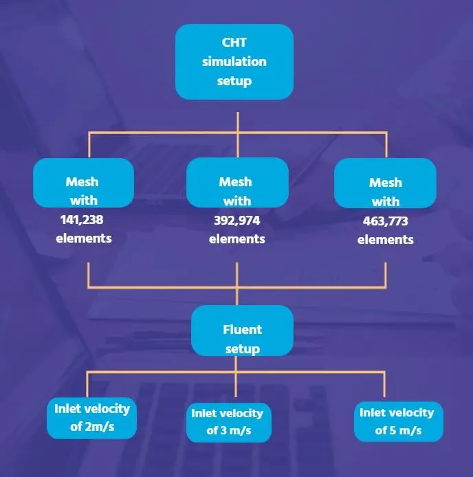
The geometry is the same for all the cases. The variations are in the Mesh and input velocity.
Geometry modelling :
A 3D CAD model of a generic graphics card is loaded into the SpaceClaim component of the FLUENT analysis system. An enclosure around the grahpics card represents the cabin. All the other components in the cabin are assumed to pose negligible effect on the air circulation inside the cabin and hence are omitted.
Enclosure :
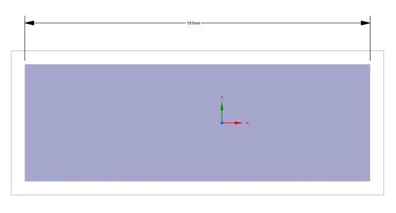
a. Right side view of the enclosure

b. Front view of the enclosure
Graphics processor :
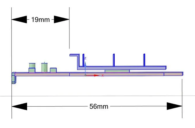
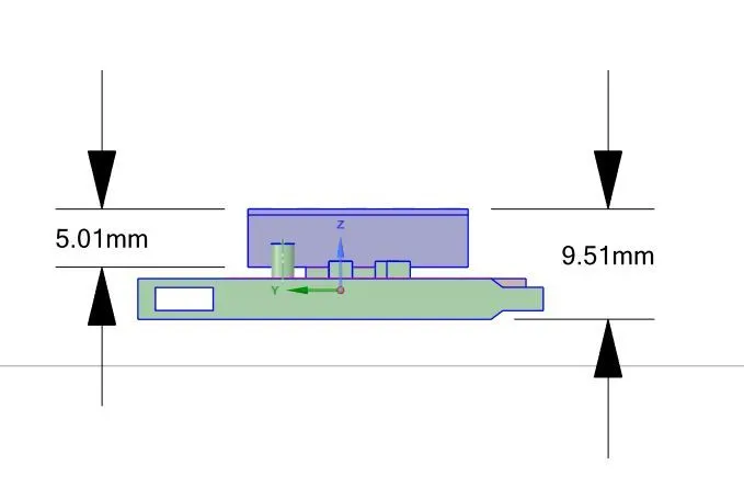
a. Front view of the Graphics card b. Left side view of the graphics of the processo 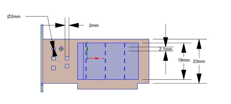
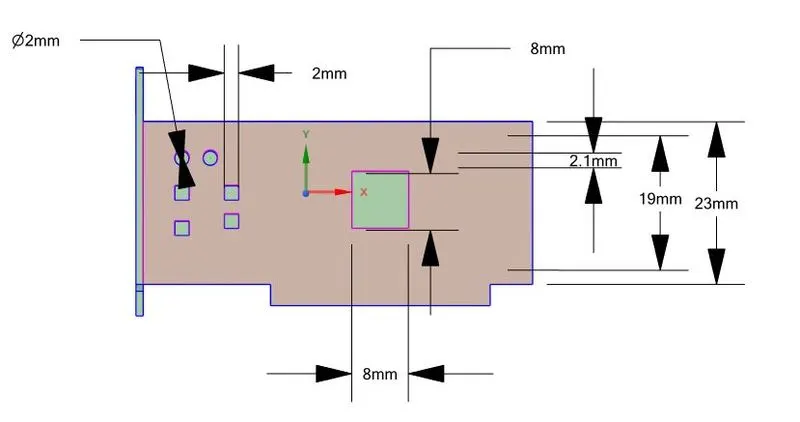
c. Top view of the Graphics processor d. Top view of the graphics processor without the Fins.
The simulations in the current problem will be performed as :
Mesh :
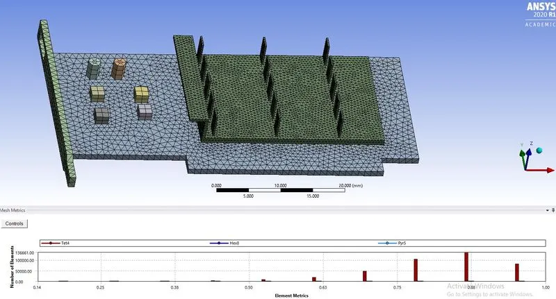
The baseline mesh with 141,238 elements is generated with the following mesh refinement settings :
1. Global element size : 10 mm.
2. Element size for meshing the PCB : 1 mm.
3. Element size for meshing the processor : 1 mm.
4. Element size for meshing the Fins : 1 mm.
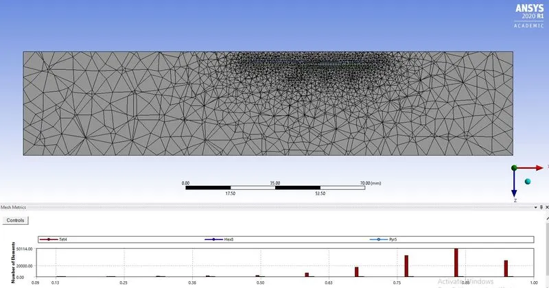
It can be observed that tet elements dominate the mesh. Majority of the elements are above the 60% element quality and the starting value is 13%.
The components like PCB, Fins and processor are meshed using the Hex elements which are of highest quality.
Simulation setup :
A steady state simulation with `K-epsilon`turbulence model is used for the simulation.
The material properties assingned for the PCB, Processor and fins are :
PCB :
Material : Glass reinforced epoxy laminate (FRP-4).
Density : 1850 `(kg)/(m^3)`.
Specific heat (Cp) : 950`(J)/(Kg-K)`
coefficient of thermal conductivity(k) : 0.29 `W/(m-K)`
Processor :
Material : Silicon
Density : 2000 `(kg)/(m^3)`
Specific heat(Cp) : 710 `J/(Kg-K)`
coefficient of thermal conductivity(k) : 150 `W/(m-K)`
Fins :
Material : Aluminium
Density : 2719 `(kg)/(m^3)`
Specific heat (Cp) : 871`(J)/(Kg-K)`
coefficient of thermal conductivity(k) : 202.4 `W/(m-K)`
Sice the materials FRP-4 and silicon aren't vailable by default in the FLUENT materials dtabase, these are created and the above material properties are input.
Air is considered as the fluid in the enclosure. The default properties of the air in the FLUENT database are considered for the simulation.
Results :
Case. I : Mesh with 141,238 elements.
a). Inlet velocity of 2 m/s.
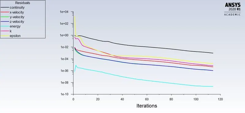
Residuals :
Temperature contour on the Graphics card :
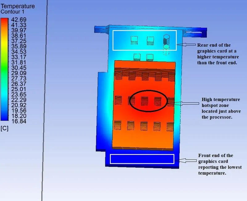
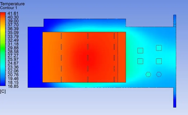
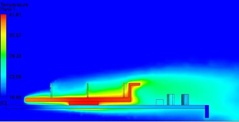
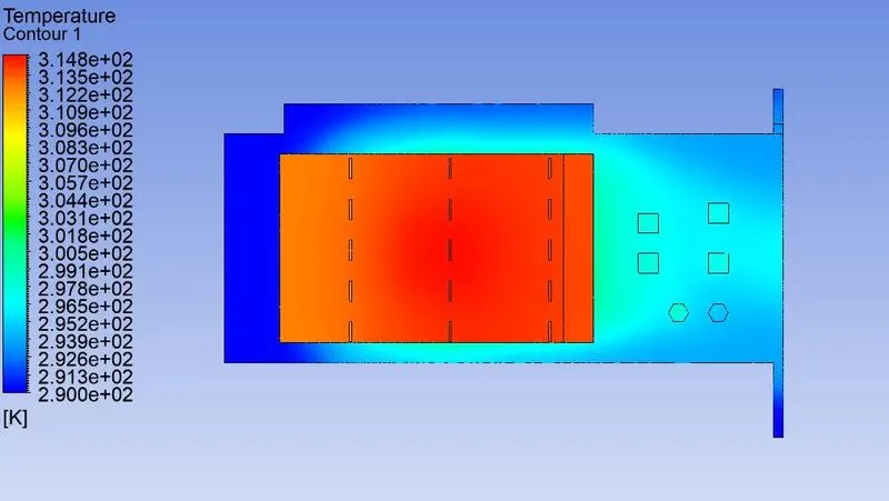
As observed from the temperature contour, the front region of the PCB always receive the cool air. As this air moves rearwards, it absorbs the heat from the fins ans well the processor by the mechanism of heat convection.
Mathematically,
The heat transfer due to convection `Q_(conv) = h*s*(T_(air) - T_(location))`
`Deltat = T_(air) - t_(location)`.
The difference in temperature between the air and the PCB surface at the front is less compared to the difference at the centre of the processor. This results in the maximum heat transfer at the centre compared to the front.
The air gets heated up after receiving the heat energy from the processor and as it moves rearwards, its absorbs less heat. This is because `DeltaT`is lesser compared to the previous.
Hence the rearside regions of PCB are hotter than the front zones.
Temperature contour on the PCB (without the processor and the heat sink):
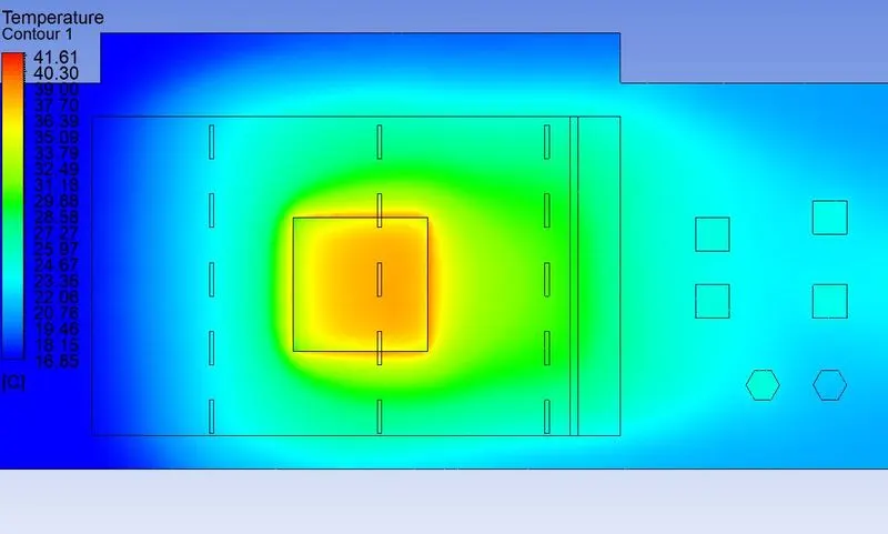
A thermal hotspot region formed on the PCB. This region gets the lowest heat excahnge with the air as well as it is situated directly below the processor.
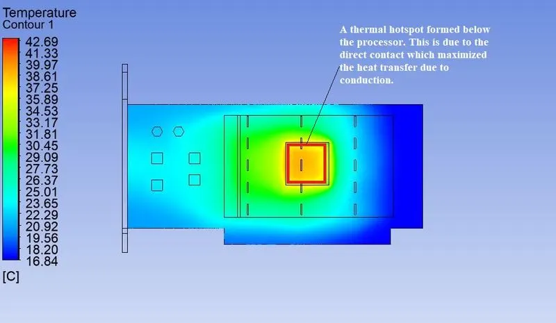
The hotspot is the region that has to be avoided while placing the critical performance components.
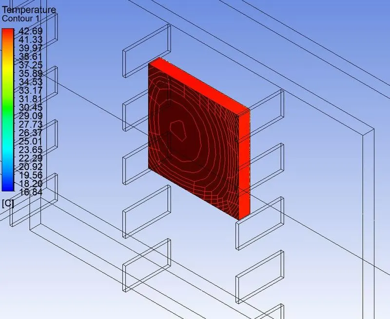
Global temperature contour on the processor :
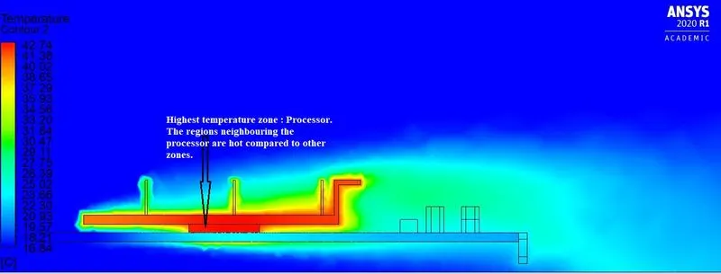
Temperature contour along the symmetry plane of the Graphics card :
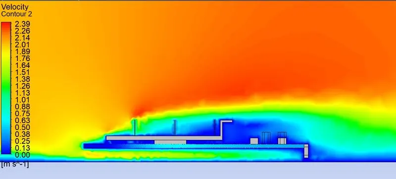
Velocity contour on the symmetry plane :
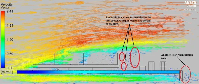
Velocity vector plot on the symmetry plane :
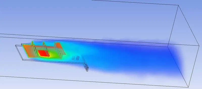
Volume rendering of the entire domain with Temperature as the variable:
b). Inlet velocity of 3 m/s
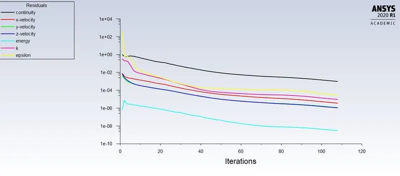
Residual plot:
Temperature contour plot on the PCB :
The recorded maximum temperature is 37.68 degree centigrade.
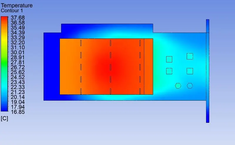
Temperature contour plot on the PCB :
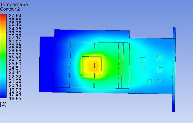
Global temperature contour plot on the processor :
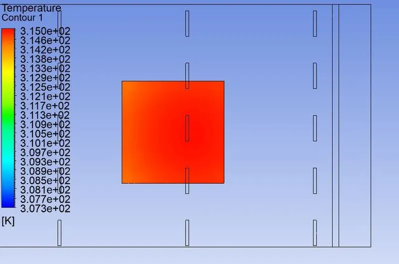
Global temperature profile refers to the temperature plot with the consideration of maximum and minimum temperatures for the entire c computational domain unlike the local temperature plot where the distribution of temperature corresponds to the selected/ highlighted region of the entire computational domain.
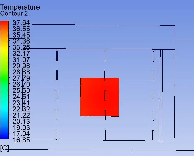
Temperature contour plot on the symmetry plane :
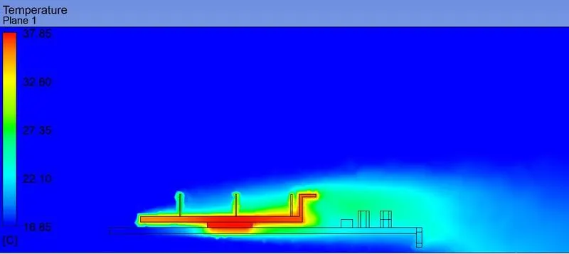
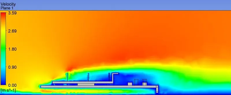
Velocity contour plot on the symmetry plane :
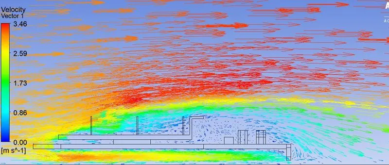
Velocity vector plot on the symmetry plane :
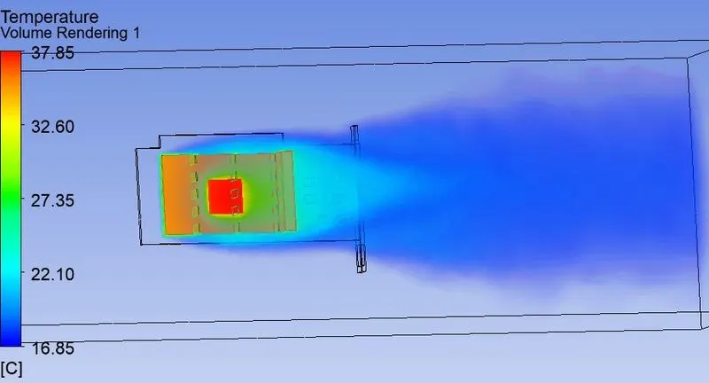
Volume rendering in the computational domain with temperature as variable:
c). Inlet velocity of 5 m/s.
Residual plot :
Temperature contour plot on the graphics card:
Temperature contour plot on PCB (excluding the Processor and Heat sink):
Global temperature contour plot on the processor :
Temperature contour on the symmetry plane :
Velocity contour plot on the symmetry plane :
Velocity vector plot on the symmetry plane :
Volume rendering in the compuatational domain with temperature as variable :
Case.2 : Mesh with 392,974 elements.
Mesh :
a). Inlet velocity of 2 m/s
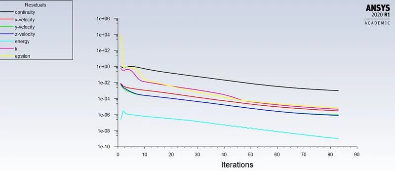
Residual plot :
Temperature contour plot for entire graphics card :
Temperature contour plot for the PCB (Graphics card excluding processor and fins) :
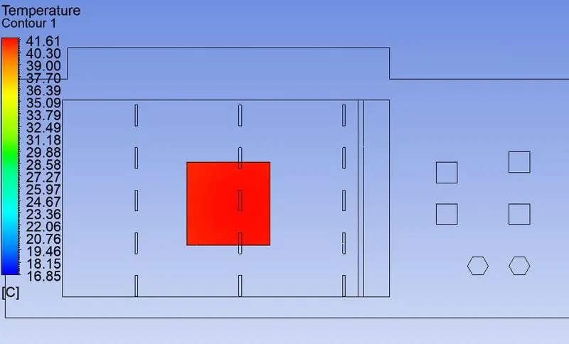
Global temperature contour for the processor :
Temperature contour on the symmetry plane :
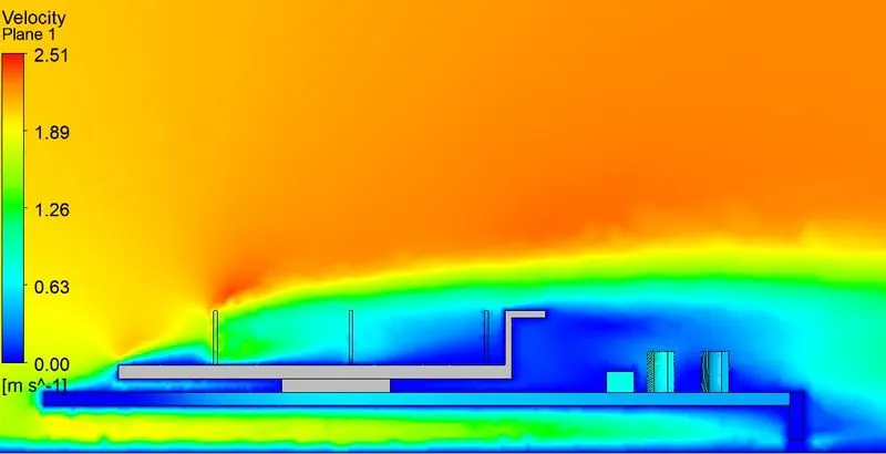
Velocity contour on the symmetry plane :
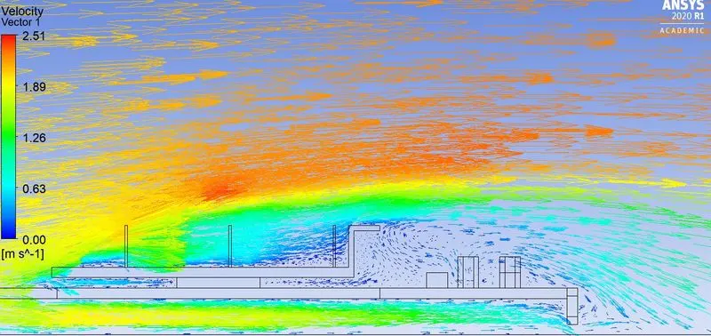
Velocity vector plot on the symmetry plane :
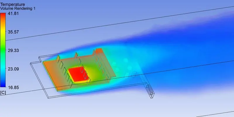
Volume rendering in the domain with temperature as variable :
c). Inlet velocity of 5 m/s.
Residual plot:
Temperature contour plot for the Graphics card :
Temperature contour plot for PCB (Graphics card excluding Processor and heat sink)
Global temperature contour for the processor :
Temperature contour on the symmetry plane :
Velocity contour on the symmetry plane :
Velocity vector plot on the symmetry plane:
Volume rendering in the domain with temperature as variable :
Case.3 : Mesh with 463,773 elements
Mesh :
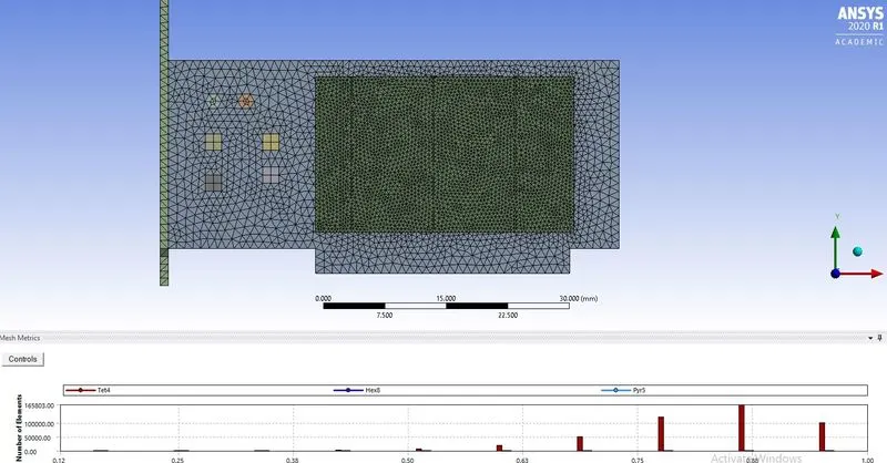
a). Inlet velocity of 2 m/s.
Residuals plot:
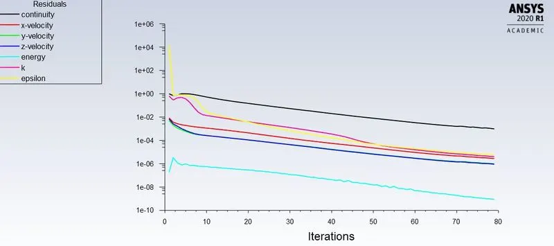
Temperature contour for the entire graphics card :
Global temperature contour for the processor :
Temperature contour on the symmetry plane :
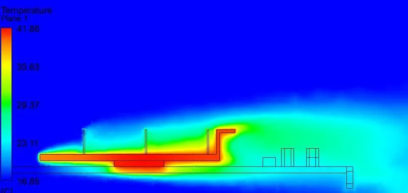
Velocity contour on the symmetry plane :
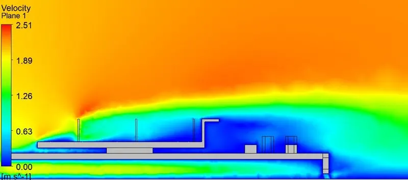
Velocity vector plot on the symmetry plane :

Volume rendering in the domain with temperature as variable:
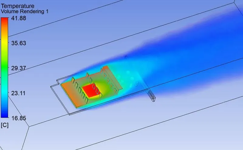
b). inlet velocity of 3 m/s
Residual plot:
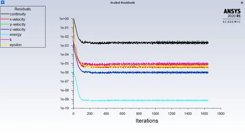
Temperature contour for the entire graphics card :
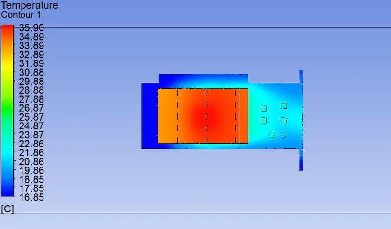
Temperature contour for the PCB (Graphics card excluding Processor and fins)
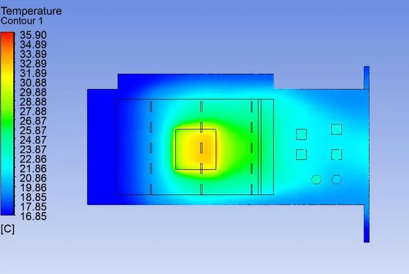
Global temperature contour on the processor:
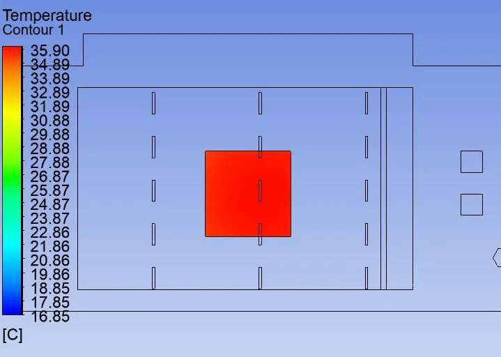
Temperature contour on the symmetry plane:
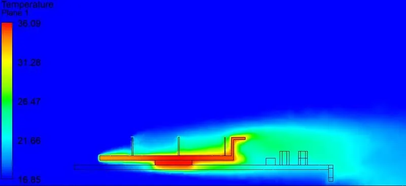
Velocity contour on the symmetry plane:
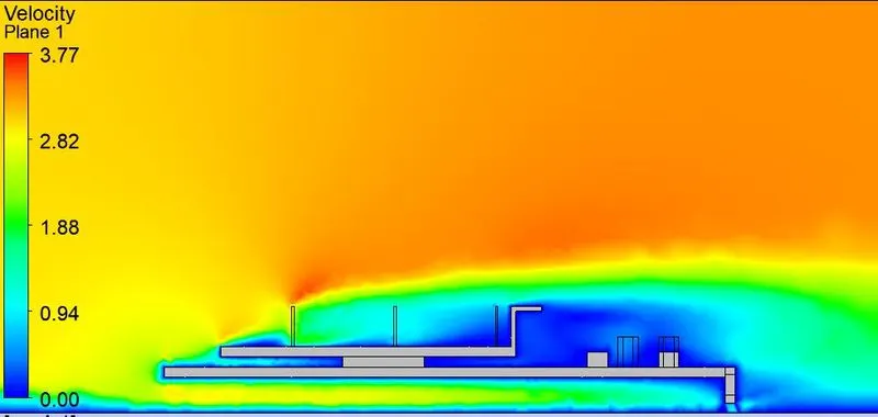
Velocity vector plot on the symmetryt plane:
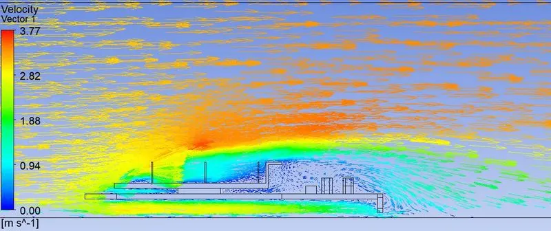
c): Inlet velocity of 5 m/s
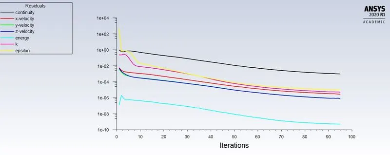
Residuals:
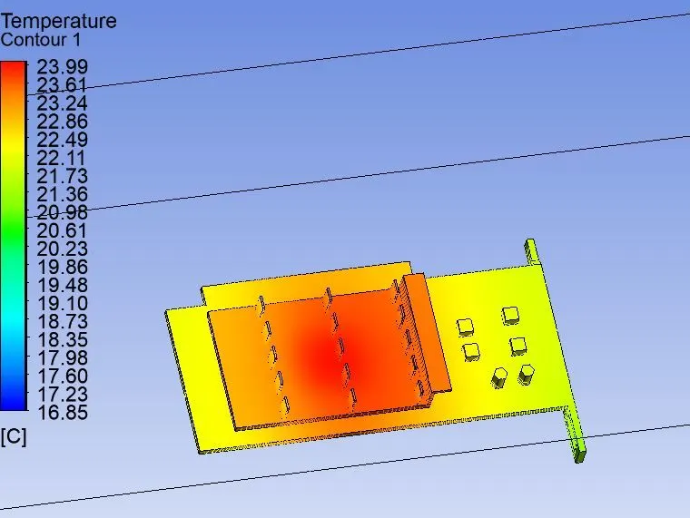
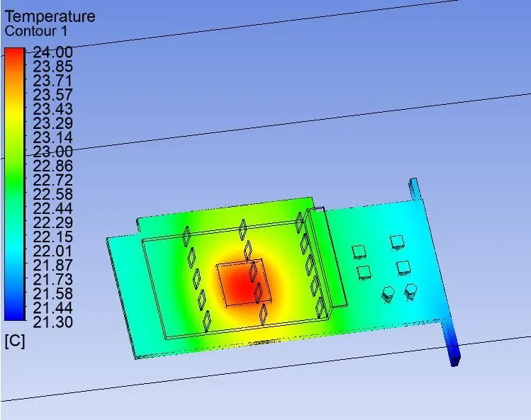
Temperature contours on the Graphics card
Temperature contour on the PCB (Graphics card excluding the Processor and FIns)
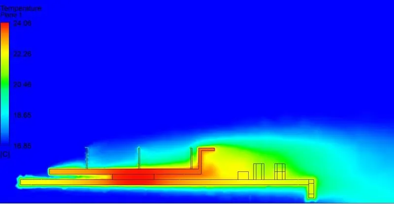
Temperature contour on the symmetry plane :
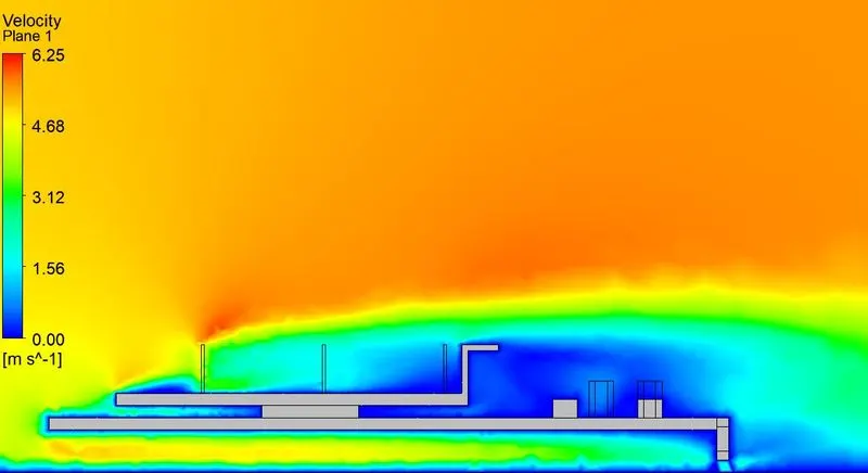
Velocity contour on the symmetry plane :
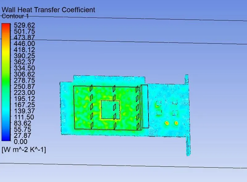
Wall Heat transfer contour on the Graphics card :
Tabular form of the results :
| S.No | Mesh details |
Inlet velocity of 2 m/s |
||||||
| 1. | 141,238 elements |
|
||||||
| 141,238 elements | Inlet velocity of 3 m/s | |||||||
|
||||||||
|
141, 238 elements |
Inlet velocity of 5 m/s | |||||||
|
||||||||
| 2. | 463,773 elements | Inlet velocity of 2 m/s | ||||||
|
||||||||
| 463,773 elements |
Inlet velocity of 3 m/s |
|||||||
|
||||||||
|
463,773 elements |
Inlet velocity of 5 m/s |
|||||||
|
Analysis :
It can be observed from the tabulated values of the outlet temperature that as the inlet velocity increases the value of the temperature at the outlet decreases. This is because of the greater amount of the heat convection by the air.
Also the value of the wall heat transfer coefficient got resolved to a better value with the mesh refinement.
Gaps in the simulation:
Grid convergence study hasn't been carried out due to the limitation on the number of cells input to the FLUENT solver is 0.5 million.
Conclusion:
A Conjugate heat transfer simulation is performed on the Graphics card and the parameters like outlet temperature and Wall heat transfer coefficient are reported.
References:
1. Heat dissipation from the intel pentium IV processor: https://ark.intel.com/content/www/us/en/ark/products/27447/intel-pentium-4-processor-2-80-ghz-512k-cache-533-mhz-fsb.html
2. FR4 material properties : https://en.wikipedia.org/wiki/FR-4