Week 6 - CHT Analysis on a Graphics card
OBJECTIVE
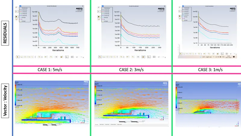
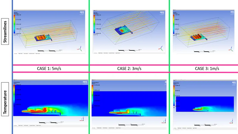
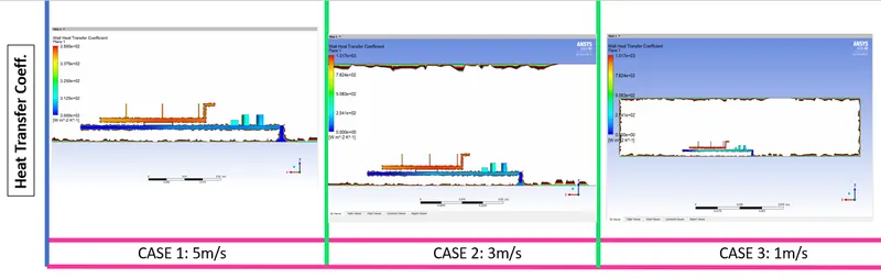
- Run the simulation by varying the velocity from 1m/sec to 5m/sec for at least 3 velocities and discuss the results.
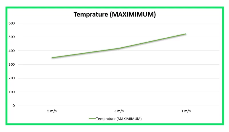
- Find out the maximum temperature and heat transfer coefficient attained by the processor.
- Prove that the simulation has achieved convergence with appropriate images and plots.
- Identify potential hotspots on the model.
SCOPE
- Basic understanding of Conjugate Heat Transfer.
- How to select materials for an object.
- Understanding of forced convection.
- How to refine the mesh.
- Significance of Prism Layers in CFD.
SOFTWARE USED
- ANSYS SPACE CLAIM:- To design the fluid flow problem
- ANSYS MESHING:- Generation of mesh.
- ANSYS FLUENT:- To set up the physics; solution initialization and solving the fluid flow problems.
- ANSYS CFD POST:- To show the results.
ABSTRACT
Conjugate Heat Transfer (CHT)
Conjugate Heat Transfer is defined as the heat transfer between two domains by exchange of thermal energy. For a system the thermal energy available is defined by its temperature and the movement of thermal energy is defined by its heat flux through the outer walls. Heat transfer in solid happens through conduction and through walls by convection and in liquid phase through convection. CHT provides the temperature prediction and the hotspot regions at the solid-fluid interface and we can also predict the heat transfer accurately for example- Conduction through solids, convection through fluid, and thermal radiation. It also provides the velocity and pressure distribution of fluid moving inside the solid. We can also use CHT in design optimization for improvement for heat transfer and cooling capacity. All chips are integrated circuits (ICs, for short) and they generate heat when they're working. Graphics cards have thousands of them packed into a small volume, which means they'll get pretty toasty if the heat isn't managed in some way. As a result, most graphics cards are hidden underneath some kind of cooling system. Our aim is to find the maximum temperature and heat transfer coefficient attained by the processor so that we can decide the external conditions and maximize the efficiency of the Graphics Card.
MATERIAL SELECTION:-
A microchip may only consume milliwatts, but it is dissipated in a tiny volume. The power is low but the power density is high. As chips shrink and clock speeds grow, heating becomes a problem. The Pentium chip of today's PCs already reaches 85°C, requiring forced cooling. Multiple-chip modules (MCMs) pack as many as 130 chips onto a single substrate. Heating is kept under control by attaching the chip to a heat sink, taking pains to ensure good thermal contact between the chip and the sink. The heat sink now becomes a critical component, limiting further development of the electronics. How can its performance be maximized? So we have selected the following materials for each of the components: -
CONVECTION: -
here are two types of convection, and they are:
- Natural convection
- Forced convection
Natural convection: When convection takes place due to buoyant force as there is a difference in densities caused by the difference in temperatures it is known as natural convection. Examples of natural convection are oceanic winds.
Forced convection: When external sources such as fans and pumps are used for creating induced convection, it is known as forced convection. Examples of forced convection are using water heaters or geysers for instant heating of water and using a fan on a hot summer day.
Forced convection is related to Newton’s law of cooling, which is given as:
P = dQ/dt = hA(T-T0)
Where,
- h is the convection heat-transfer coefficient
- A is the exposed surface area
- T is the temperature of the immersed object
- T0 is the temperature of the fluid which is under convection
The value of the heat-transfer coefficient h depends on:
- Density
- Viscosity
- Thermal conductivity
- Specific heat capacity
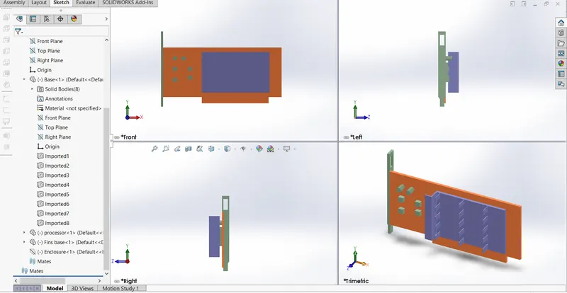
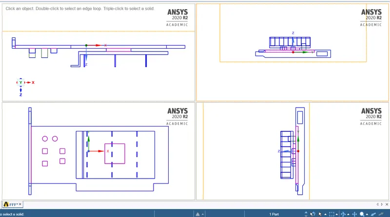
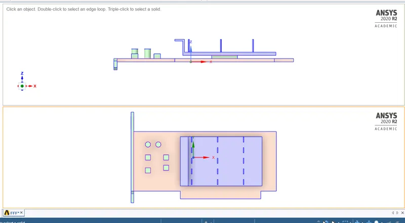
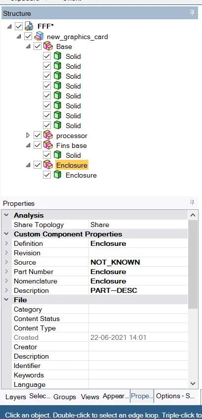
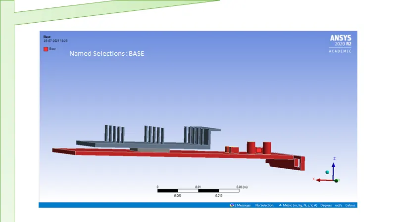
GEOMETRIC DESCRIPTION
SPACE CLAIM SHARE TOPOLOGY ON
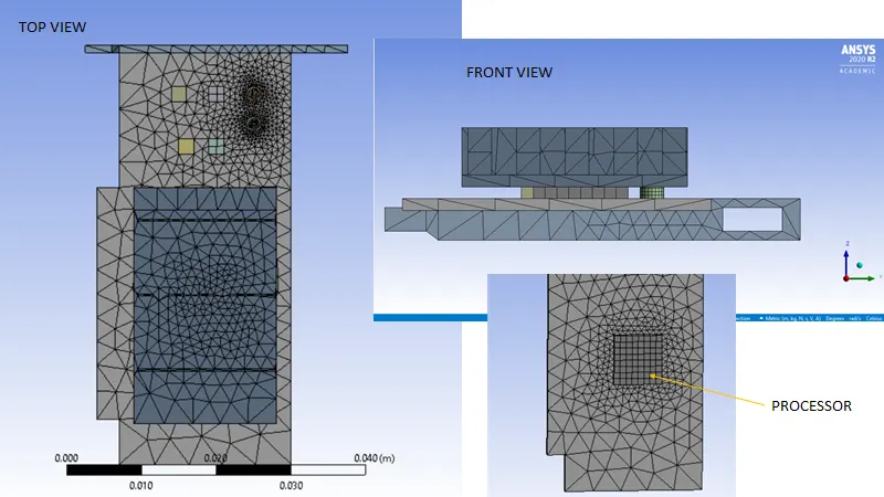
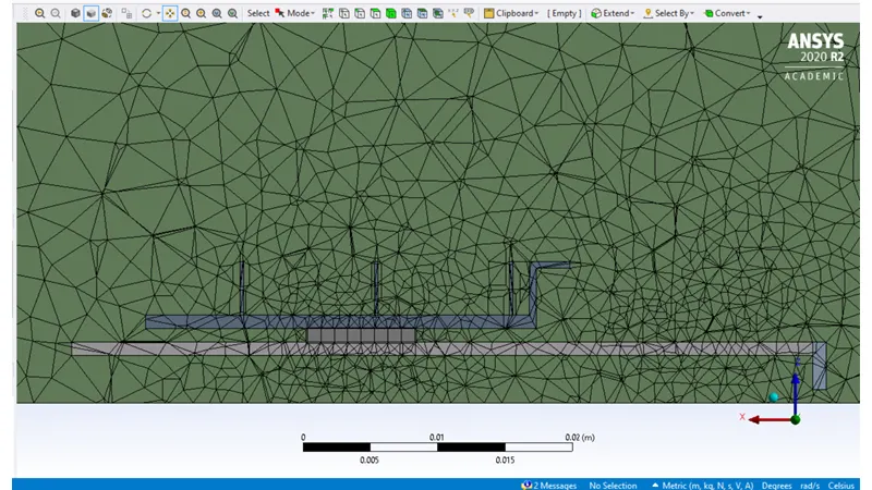
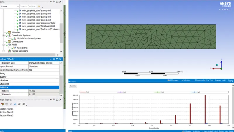
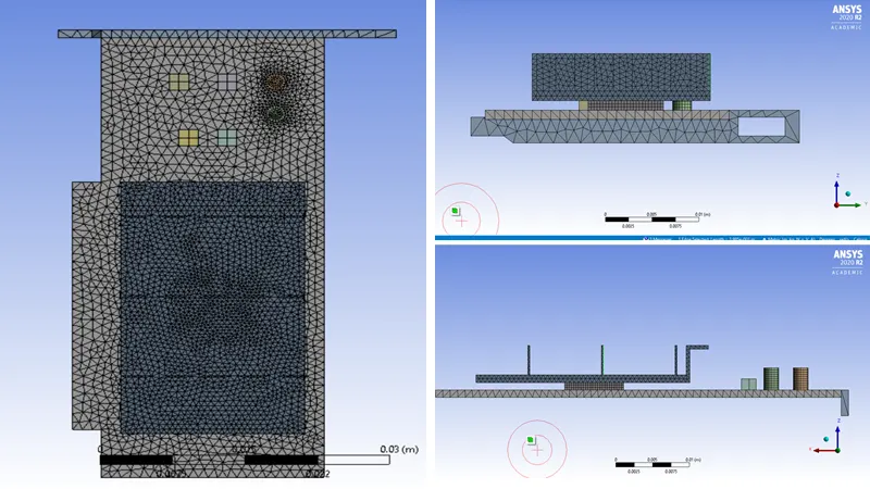
MESH :
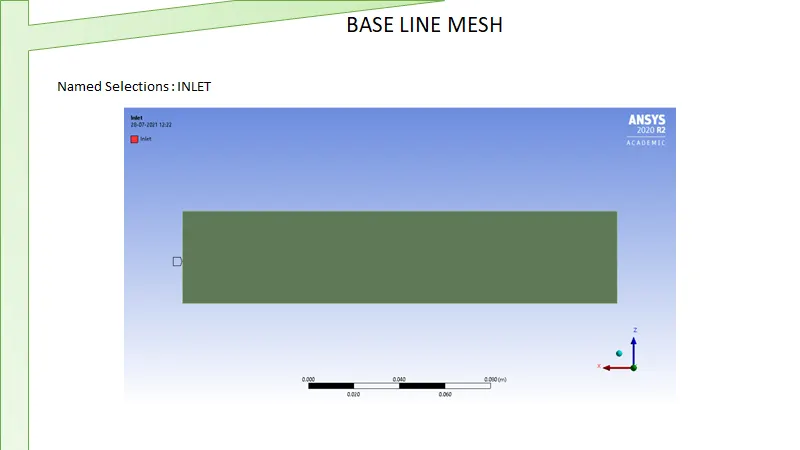
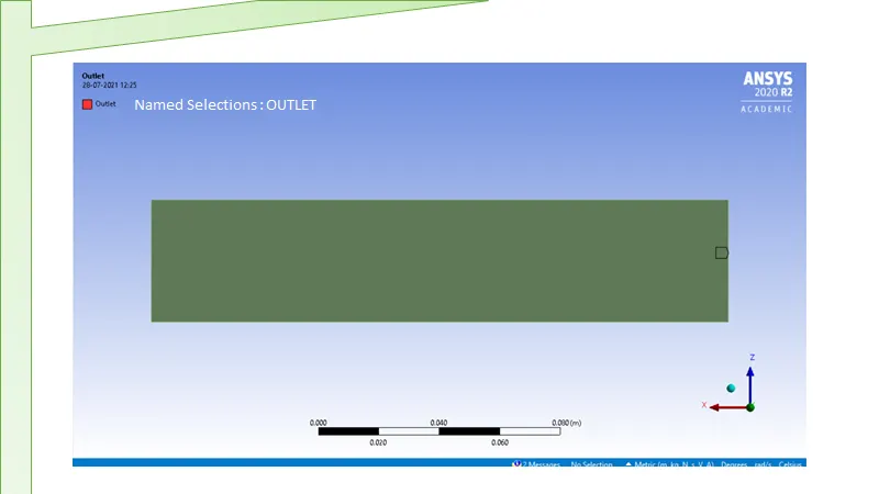
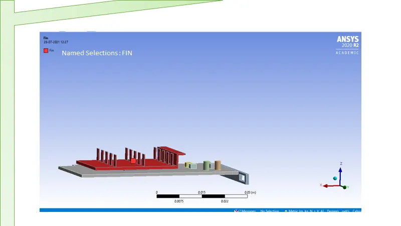
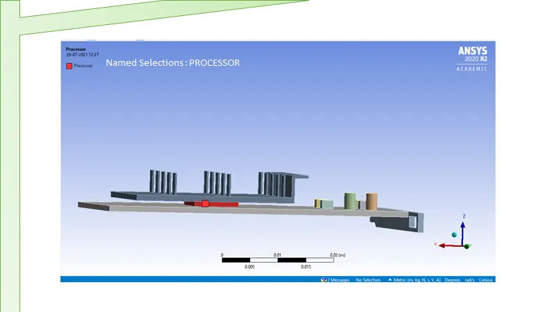
A BASELINE MESH
B REFINED MESH
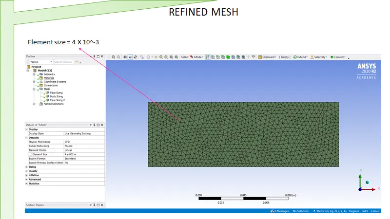
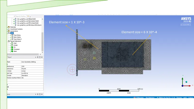
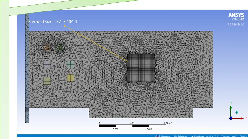
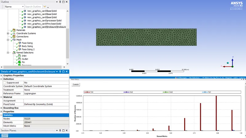
FLUENT SOLVER: -
- Solver type: Pressure based
- Steady-state solver
- Check the Energy equation
- Turblent Model: K-Omega SST Model
Boundary Condition(s) :
Inlet Velocity = we have three conditions
1] 1 m/s 2] 3 m/s 3] 5 m/s
Initial temperature = 300k
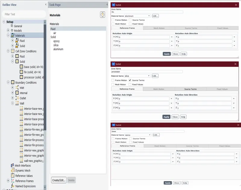
Cell zone conditions:
Set Processor as source term as heat is generated by it in the graphic card.
Consider Power supplied to Core (P) = 6 W
We have, Volume of processor (V) = 64 mm^3
Therefore, Heat generated = PV = 93750000 w/m^3
RESULTS :-
CONCLUSIONS:
1] As the number of elements grows, more precise temperature distribution findings are obtained.
2] It is clear from the data above that when the intake velocity increases, the net temperature of graphics card components drops.
3] In addition, as the intake velocity drops from 5 m/s to Im/s, the temperature of the components rises, demonstrating that higher velocity leads to better cooling.