Week 3 - External flow simulation over an Ahmed body.
OBJECTIVE
TO SIMULATE THE FLOW OVER AN AHMED BODY AND PERFORMING GRID DEPENDENCY USING ANSYS FLUENT .
SCOPE
(A) Importance of Ahmed Body.
(B) Significance of the point of separation.
(C) Basic understanding of how wake effects the drag force.
(D) Negative Pressure in the wake region
SOFTWARE USED
- ANSYS SPACE CLAIM :- To design the fluid flow problem
- ANSYS MESHING:- Generation of mesh.
- ANSYS FLUENT:- To setup the physics ; solution initialisation and solving the fluid flow problems.
- ANSYS CFD POST:- To document and compare the results
ABSTRACT
Aerodynamics plays an integreral role in the Automobile Industry as it provide us the information about flow around the vehicle. The aerodynamic drag force is a measure of the effectiveness of vehicle to progress through air , so it is the key factor in determining the "fuel-economy" of the vehicle .Ahmed Body helps us to visualise the flow around the vehicle.Ahmed body represents the simplified ground vehicle geometry of a bluff body type . Its shape is simple enough for accurate flow simulation and retains some important practical features relevant to automobiles body.
GEOMETRIC DISCRIPTION
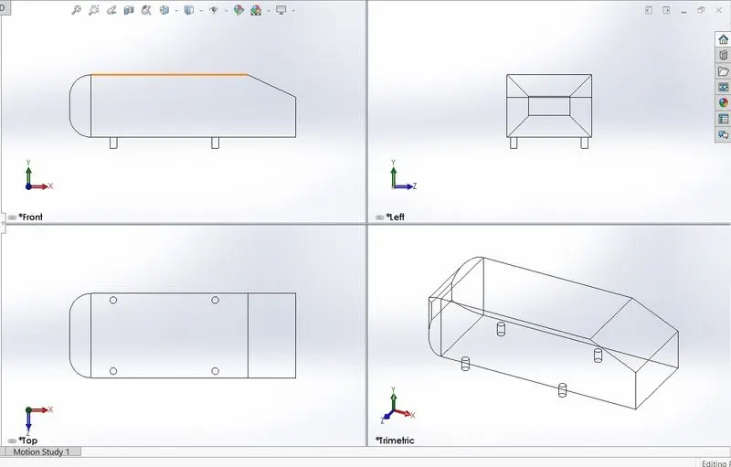
The simple geometrical shape has a length of 1.044 meters, height of 0.288 meters, and a width of 0.389 meters. Different rear slant angles result in the emergence of different wake regions at the rear, which are mainly responsible for the drag of the vehicle.
IMPORTANCE OF AHMED BODY
The airflow around the Ahmed body captures the essential flow features around an automobile . Although it has a very simple shape, Ahmed body allows us to capture characteristic features that are relevant to bodies in the automobile industry. This model is also used to describe the turbulent flow field around a car-like geometry. Once the numerical model in validated, it is used to design new models of the car.
The Ahmed body was described originally by S. R. Ahmed in 1984 . The main features of the wake are: -
- 1. The A recirculation region that is formed as the flow separates at the top of the vertical back surface of the model
- 2. The B recirculation region that is formed due to the separation at the base of the model.
- 3. The c-pillar vortices that form as the vorticity in the side boundary layers roll up over the slant edges.
POINT OF SEPERATION
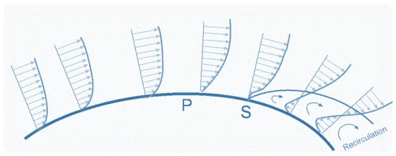
Pressure gradient is an is one of the factors that influences a flow immensely. A negative pressure gradient is termed a Favourable pressure gradient. Such a gradient enables the flow. A positive pressure gradient has the opposite effect and is termed the Adverse Pressure Gradient. Fluid find it difficult to negotiate an adverse pressure gradient. One of the severe effects of an adverse pressure gradient is to separate the flow. Consider flow past a curved surface as shown in Figure. The geometry of the surface is such that we have a favourable gradient in pressure to start with and up to a point P. The negative pressure gradient will counteract the retarding effect of the shear stress (which is due to viscosity) in the boundary layer. For the geometry considered we have a an adverse pressure gradient downstream of P. Now the adverse pressure gradient begins to retard. As indicated in the figure, the velocity near the wall reduces and the boundary layer thickens. A continuous retardation of flow brings the wall shear stress at the point S on the wall to zero. From this point onwards the shear stress becomes negative and the flow reverses and a region of recirculating flow develops. We see that the flow no longer follows the contour of the body. We say that the flow has separated. The point S where the shear stress is zero is called the Point of Separation.
SPACE CLAIM
As we know that Ahmed Body is symmterical wrt longitudinal axis so by the help of 'split body' command in SpaceClaim we can obtain the half-body geometry, which will help us in refining mesh even more and producing suitable results for convergence
.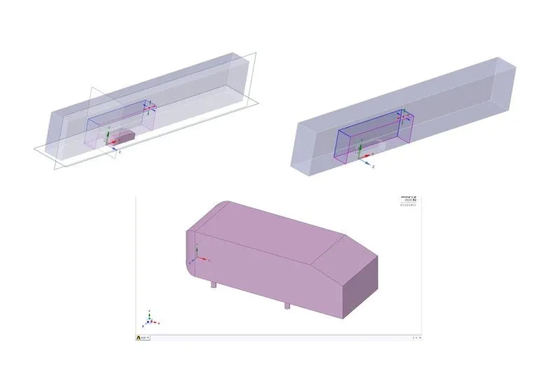
figure 2:- geometric discription of model
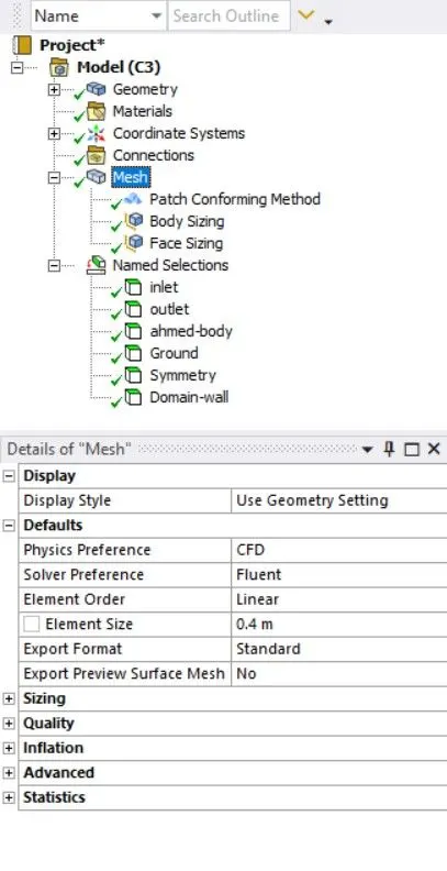
MESH
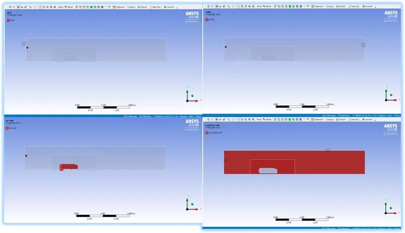
BOUNDARY CONDITIONS
- INLET
- OUTLET
- SYMMETRY-WALL
- AHMED-BODY
- GROUND
CASE 1:
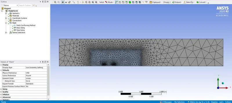
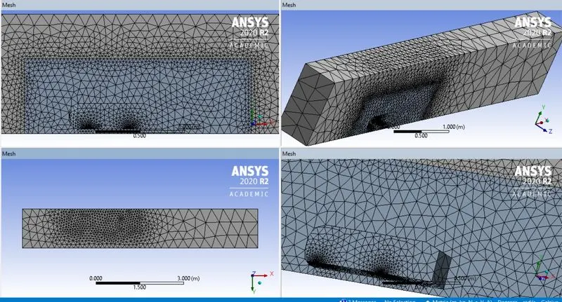
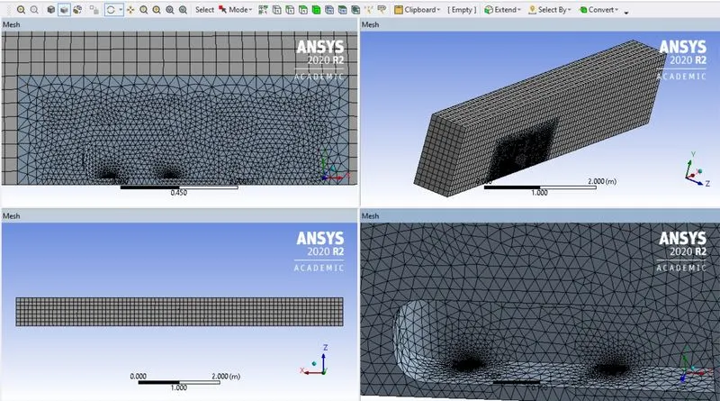
- Element Size :- 0.4 m
MESH GEOMETRY
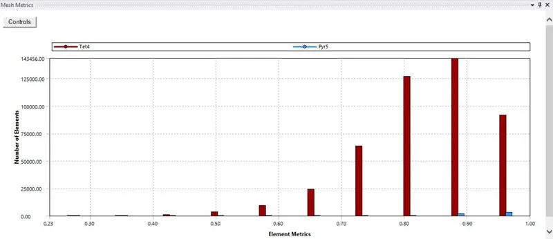
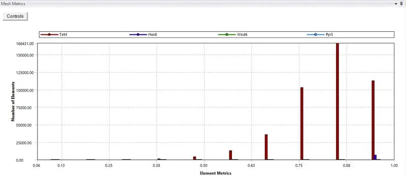
MESH QUALITY
- Element Size :- 0.1m
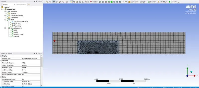
MESH QUALITY
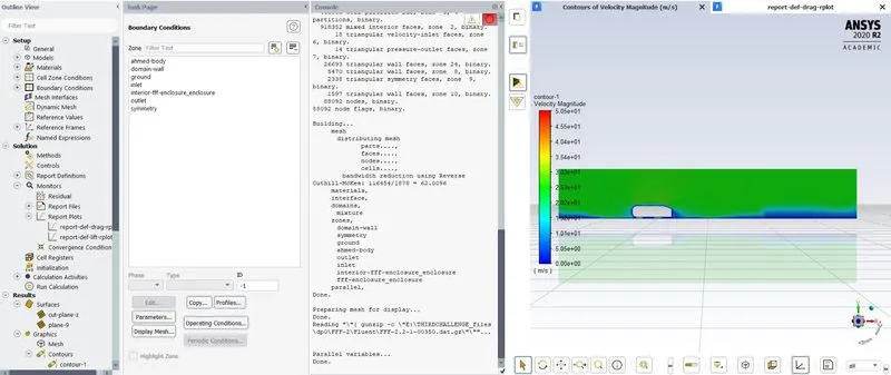
FLUENT SOFTWARE:-
CASE1 :- ELEMENT SIZE=0.4 m
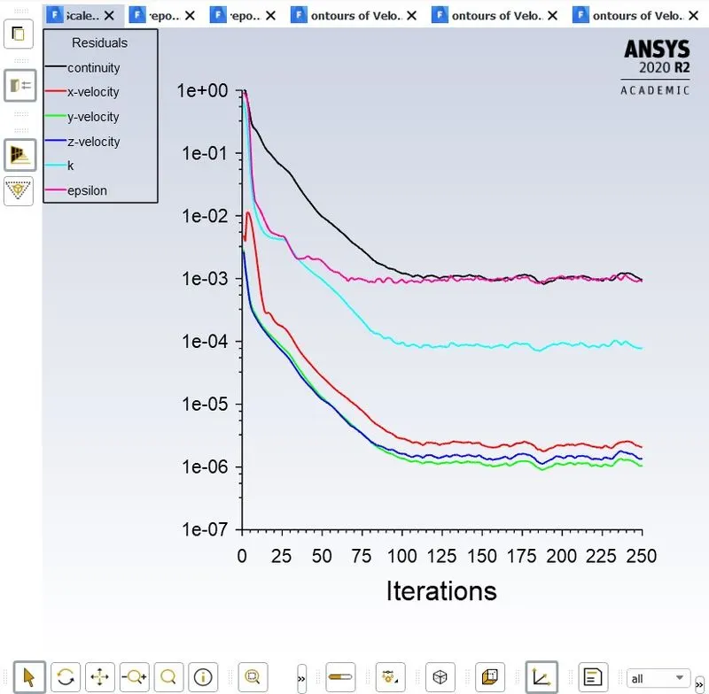
RESIDULAS
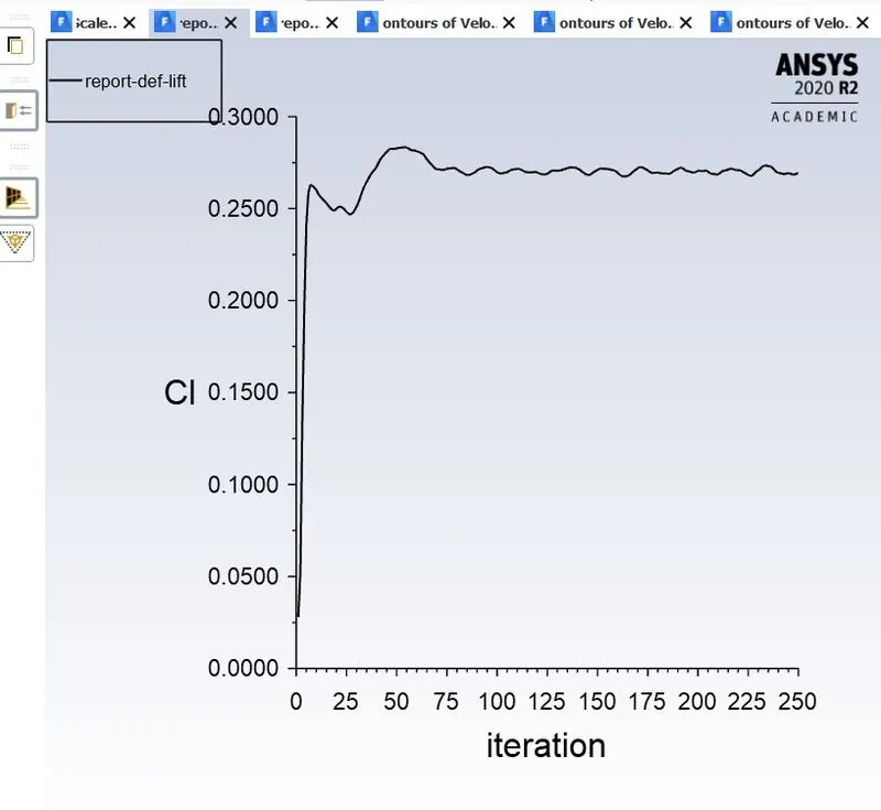
COEFFICIENT OF LIFT 0.25643
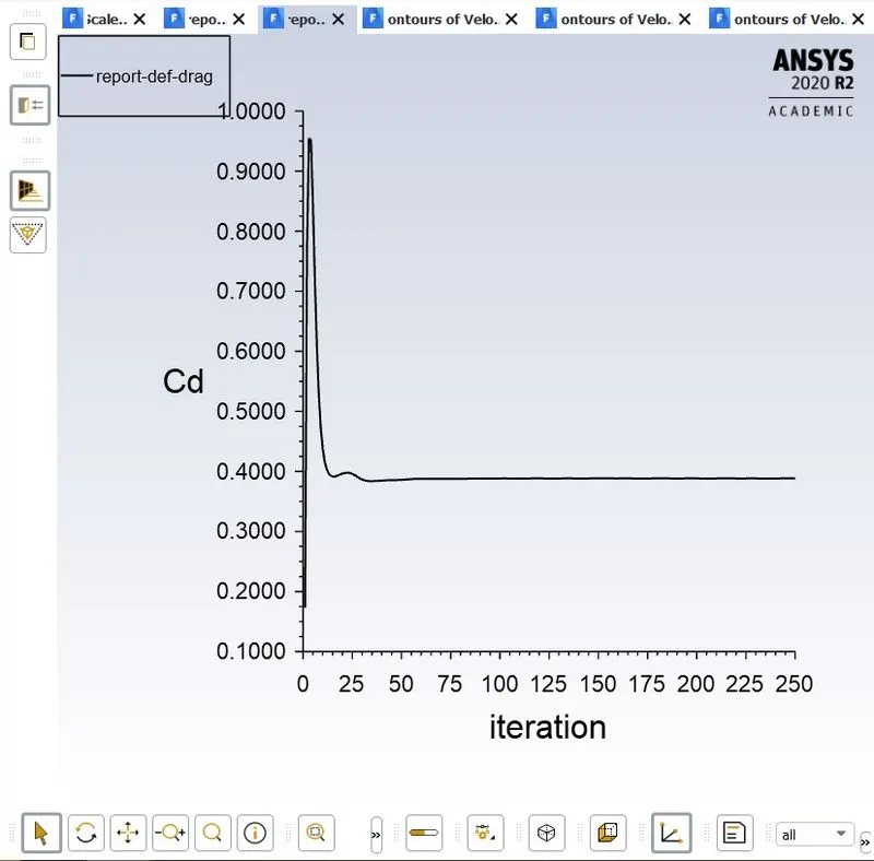
COEFFICIENT OF DRAG 0.398777
VELOCITY CONTOURS
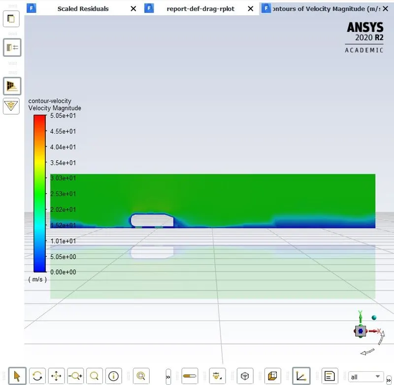
POST PROCESSING
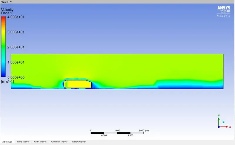
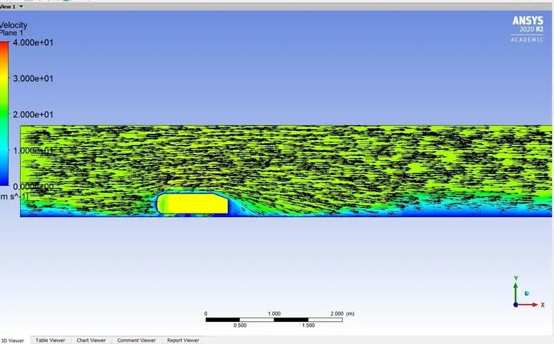
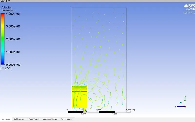
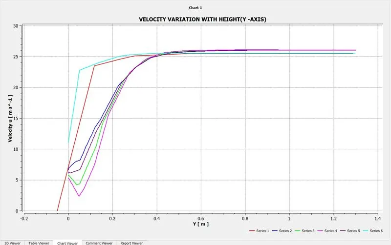
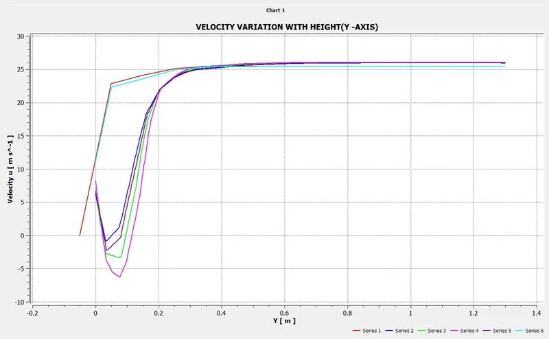
Variation of velocity behind the Ahmed Body
Element Size :- 0.1m
USING K EPSILON (REALIZABLE)
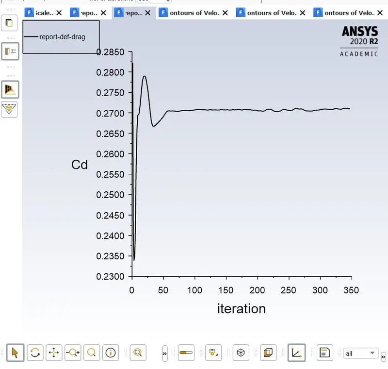
COEFFICIENT OF LIFT 0.1356778
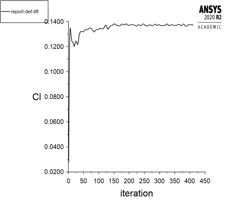
COEFFICIENT OF DRAG 0.273467
VELOCITY CONTOURS
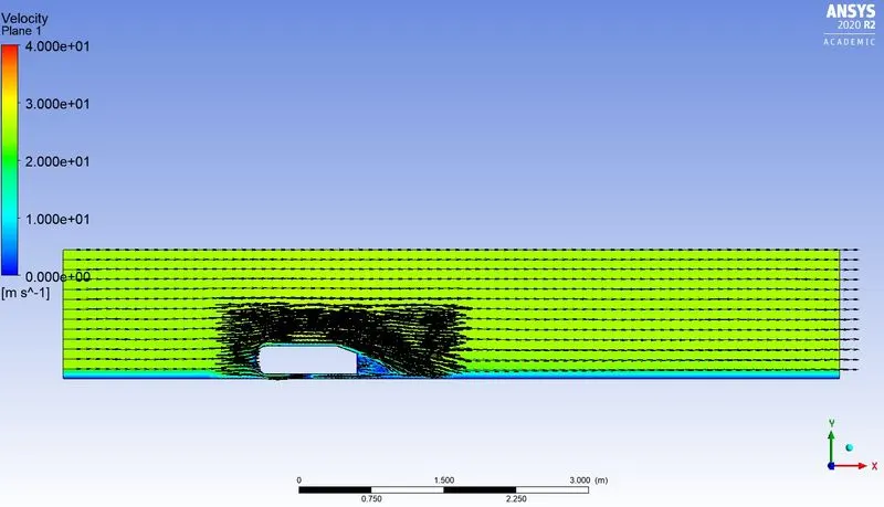
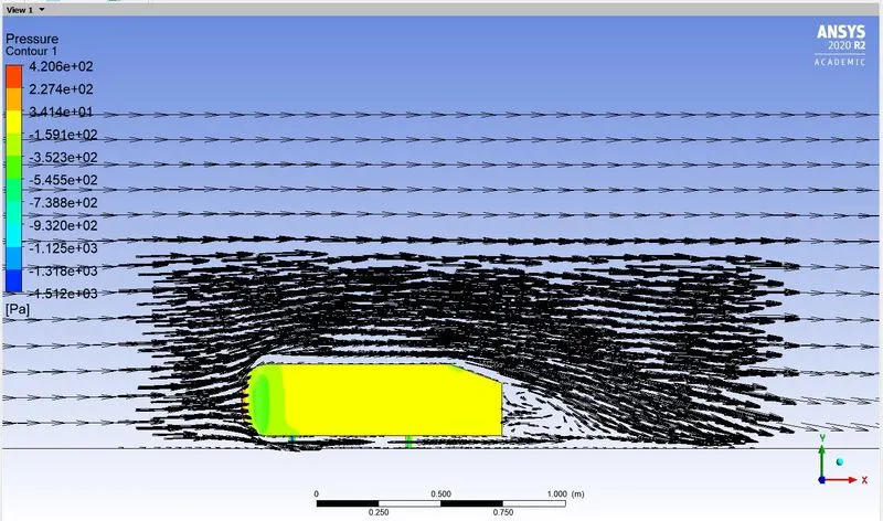
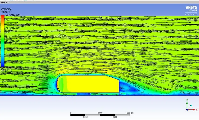
Variation of velocity behind the Ahmed Body
STREAMLINES VIDEO LINK
REFERENCES
- http://www-mdp.eng.cam.ac.uk/web/library/enginfo/aerothermal_dvd_only/aero
- https://www.cfd-online.com/Wiki/Ahmed_body
- https://www.comsol.com/blogs/studying-the-airflow-over-a-car-using-an-ahmed-body
- CFD Study of Flow over a Simplified Car (Ahmed Body) Using Different Turbulence Models
- Aerodynamics Study of Automobile Car Ahmed Body using CFD Simulation to Predict the Drag Coefficient and Down Forces.