Week 4 - CHT Analysis on Exhaust port
OBJECTIVE
- Give a brief description of why and where a CHT analysis is used.
- Maintain the y+ value according to the turbulence model and justify the results.
- Calculate the wall/surface heat transfer coefficient on the internal solid surface & show the velocity & temperature contours in appropriate areas.
- How would you verify if the HTC predictions from the simulations are right? On what factors does the accuracy of the prediction depend?
SCOPE
- Basic understanding of Conjugate Heat Transfer
- How to choose Turbulence Model.
- How to simulate a Heat Transfer Coefficient.
SOFTWARE USED
- ANSYS SPACE CLAIM:- To design the fluid flow problem
- ANSYS MESHING:- Generation of mesh.
- ANSYS FLUENT:- To set up the physics; solution initialization and solving the fluid flow problems.
- ANSYS POST:- To post-process the results.
ABSTRACT
The coupling of conduction in solids with convective and radiative heat transfer in the surrounding fluids is referred to as Conjugate Heat Transfer (CHT). To put it another way, CHT is the result of combining heat transfer in solids with heat transfer in fluids. Conduction predominates in solids, whereas convection predominates in fluids. Efficiently combining heat transfer in fluids and solids is the key to designing effective heaters, coolers, or heat exchangers. Heat transfer in solids and heat transfer in fluids are combined in the majority of applications. This is because fluids flow around the solids, or between solid walls, and because solids are usually immersed in a fluid. The CHT Analysis is used in processes that involve variations of temperature within solids and fluids, due to thermal interaction between the solids and fluids. The exchange of thermal energy between the two physical bodies is called the study of Heat Transfer, the rate of transferred heat is directly proportional to the temperature difference between the bodies. A typical example is the heating or cooling of a solid object by the flow of air in which it is immersed. The physics of conjugate heat transfer is common in many engineering applications, including heat exchangers, HVAC, and electronic component design.
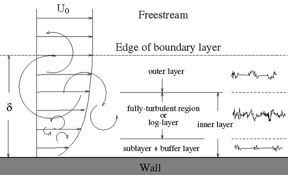
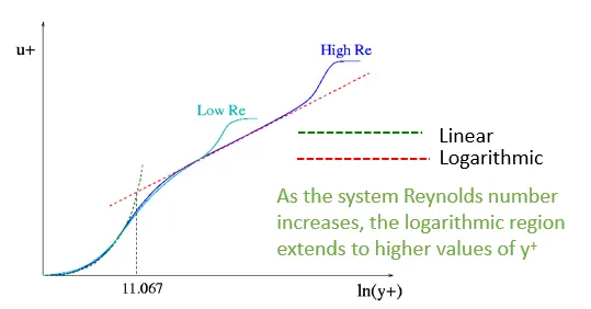
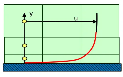
The y+ value is a non-dimensional distance (based on local cell fluid velocity) from the wall to the first mesh node. To use a wall function approach for a particular turbulence model with confidence, we need to ensure that our y+ values are within a certain range. We need to be careful to ensure that our y+ values are not so large that the first node falls outside the boundary layer region. If this happens, then the Wall Functions used by our turbulence model may incorrectly calculate the flow properties at this first calculation point which will introduce errors into our pressure drop and velocity results. The upper range of applicability will vary depending on the flow physics and the extent of the boundary layer profile.
We Use the K-Epsilon model with scalable wall functions.
HEAT TRANSFER COEFFICIENT
Heat transfer coefficient is a quantitative characteristic of convective heat transfer between a fluid medium (a fluid) and the surface (wall) flowed over by the fluid. This characteristic appears as a proportionality factor a in the Newton-Richmann relation.

 = heat transfer coefficient
 = heat flux
 = Difference in temprature between a solid surface and surrounding fluid.
SPACE CLAIM
Load the CAD model of the Exhaust manifold in Spaceclaim and check for any extra edges, remove them if any.
- Go to Repair --> Volume extract, and select the edges to separate inner and outer volume Name the outer volume as Solid volume and inner as Fluid volume and move both the volume to new component and delete empty components.
- Go to workbench --> Shareprep, to share the physics between the fluid and solid volume and conformal mesh can be achieved pink circle is seen after completing the process.
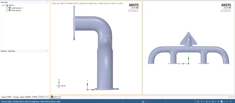
Figure 4.1:- Cross-sectional View of Exhaust Manifold
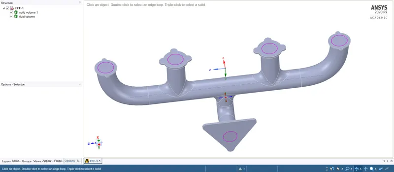
Figure 4.2: - Share Topology ON
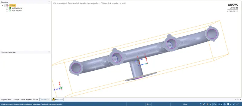
Figure 4.3:- SolidBody of the Exhaust Manifold
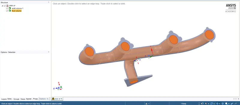
Figure 4.4: - Extracted Fluid Volume
MESH
CASE 1:
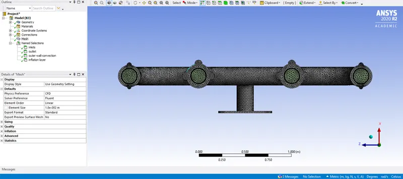
BASE LINE MESH
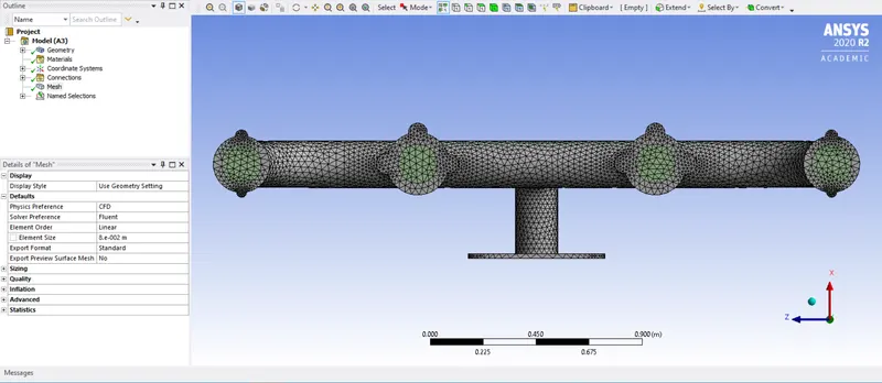
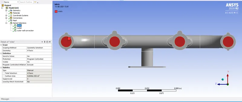
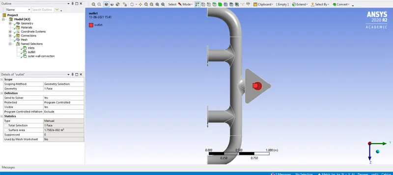
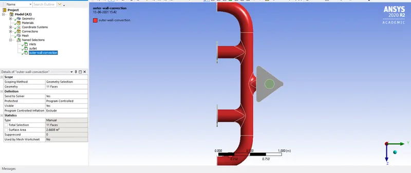
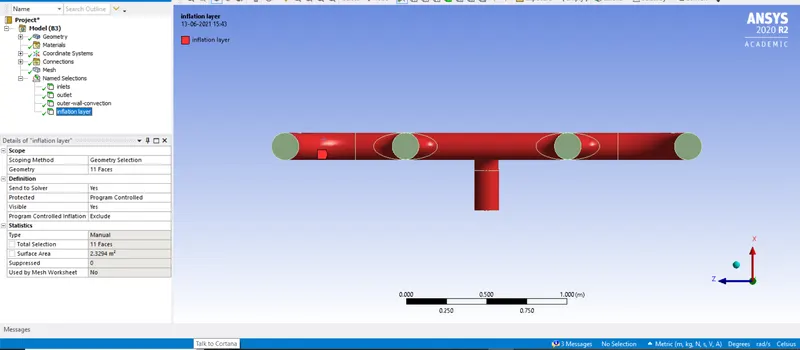
CASE 1:
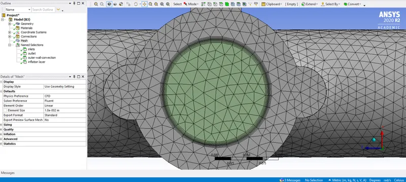
REFINED MESH :
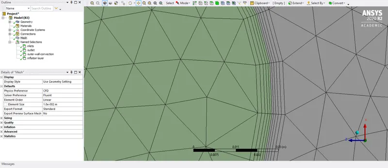
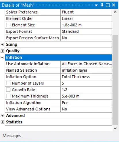
ADDITION OF INFLATION LAYER: Details are shown in the figure
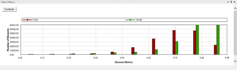
MESH QUALITY :
FLUENT :
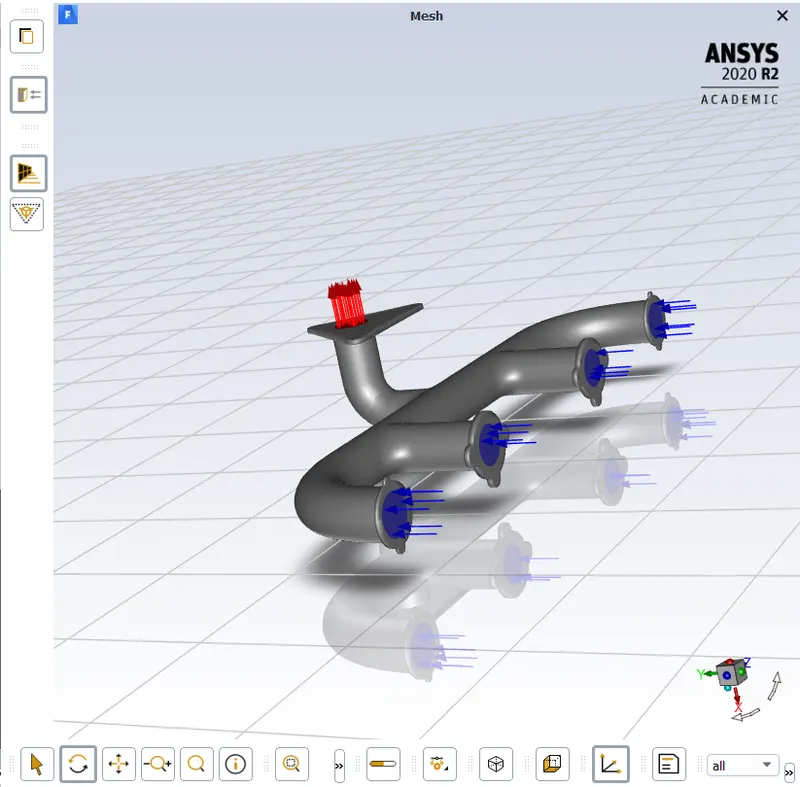
Boundary Conditions:
Inlet:
Velocity = 5 m/s
Temperature = 700 K. (420 degree celsius)
Outlet wall convection:
Thermal condition: Convection
Heat transfer coefficient = 20 W/(m^2)K.
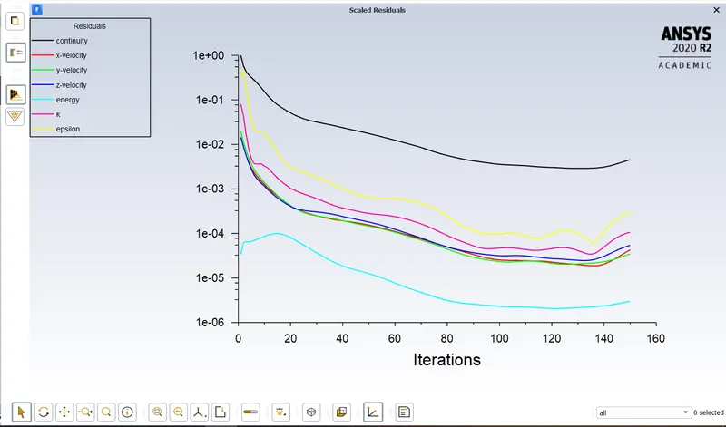
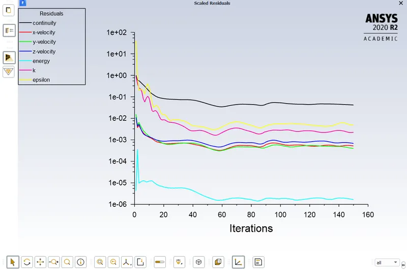
Simulation runs for 150 iterations.
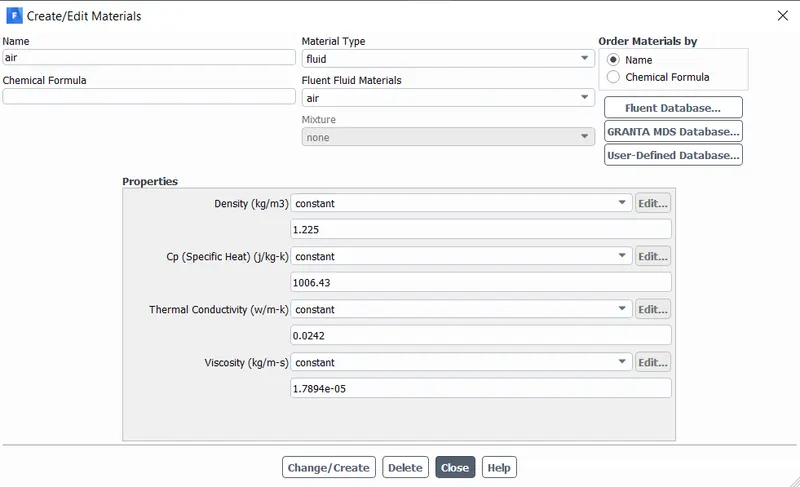
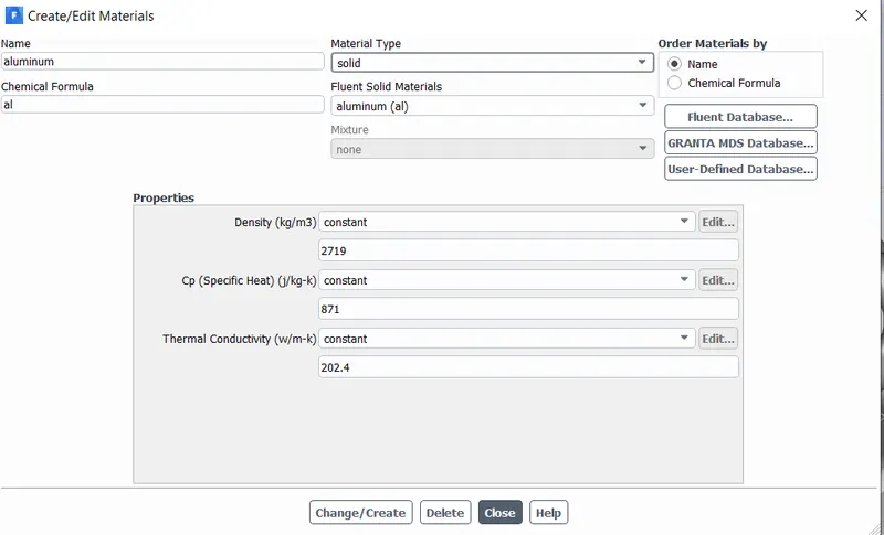
MATERIAL OF SOLID SURFACE: ALUMINUM
CASE 1:
General View
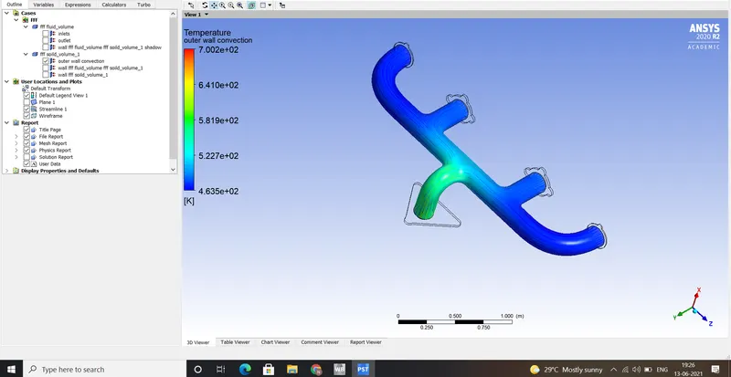
TEMPERATURE PLOT:
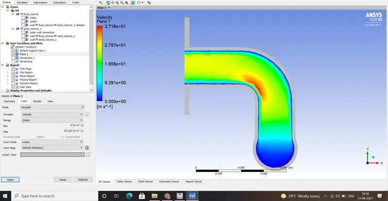
VELOCITY PLOT
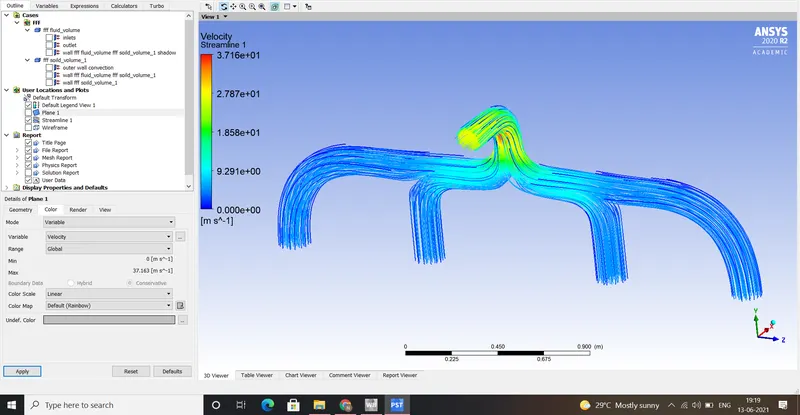
STREAM LINES:
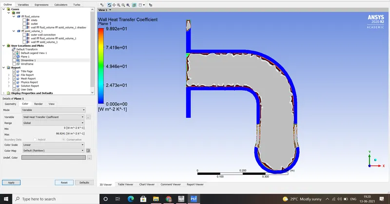
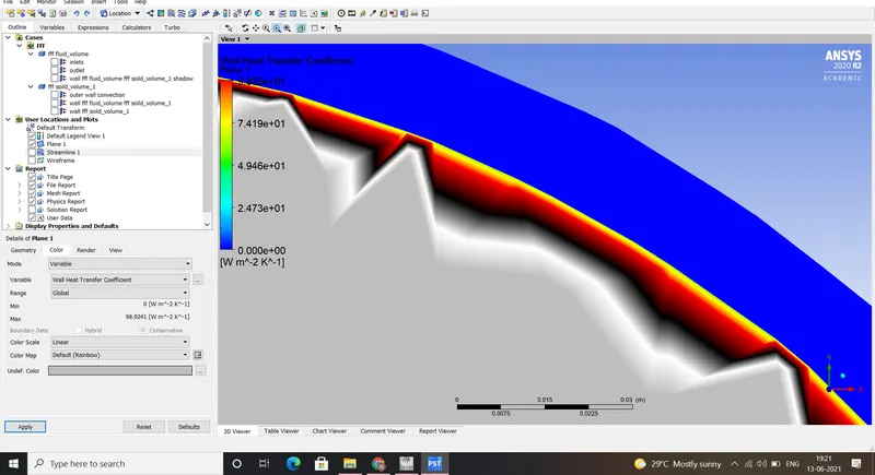
WALL HEAT TRANSFER COEFFICIENT
CASE 2:
RESIDUALS
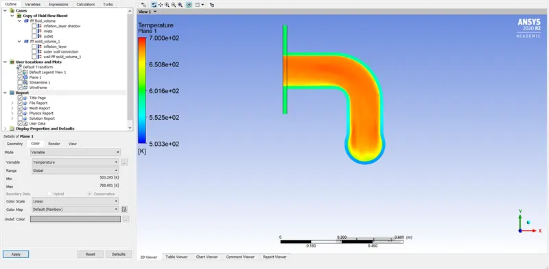
TEMPERATURE PLOT
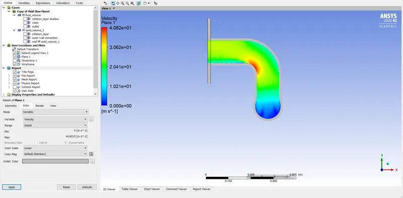
VELOCITY PLOT:
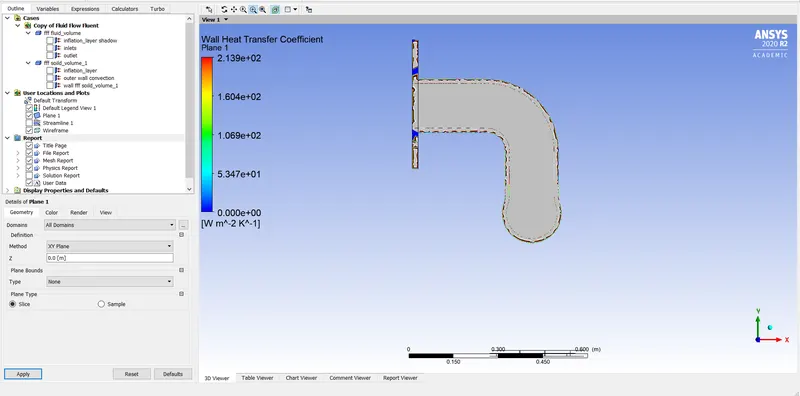
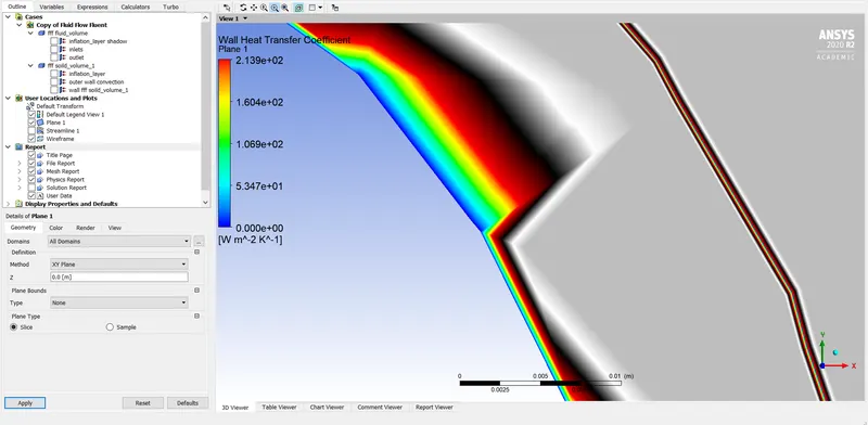
WALL HEAT TRANSFER COEFFICIENT :
Nu =h*L/K
As the Length of the pipe and thermal conductivity are constant, the value of h will increase as Nu increases and Nu increases as Re increases (reynolds number is directly proportional to Nu). As per our results, the heat transfer coefficient is high for a higher value of velocity and hence from the above discussion we think that our results are correct.
Factors that affect the quality of prediction:
- Use inflation layers and apply the proper Boundary condition.
- Proper selection of turbulence model according to y+values.
CONCLUSIONS
- The wall coefficient heat transfer increases in case II
- The results are more accurate in the case II as compared with the case II .
- The heat transfer is higher between fluid and solid at the outlet because the velocity of the fluid is higher.
- There is no change in temperature difference in both cases but the change in minimum temperature is in the second case because of mesh refinement.
REFERENCES
- https://www.simscale.com/docs/analysis-types/conjugate-heat-transfer-analysis/
- A comparative study of intake and exhaust port modeling strategies for scale-resolving engine simulations.
- Effects of Conjugate Heat Transfer on Steady MHD Mixed Convective Heat Transfer Flow over a Thin Vertical Plate Embedded in a Porous Medium with High Porosity.
- Conjugate heat transfer analysis of film cooling flows.
- https://www.computationalfluiddynamics.com.au/tips-tricks-turbulence-wall-functions-and-y-requirements/