Week 6 - CHT Analysis on a Graphics card
In this Challenge, we are going to use conjugate heat transfer analysis to analyse the max temperature attained by the graphics card and also identify the hotspot region for the same.
Pre-Processing:
1) Load the body in Space-claim.
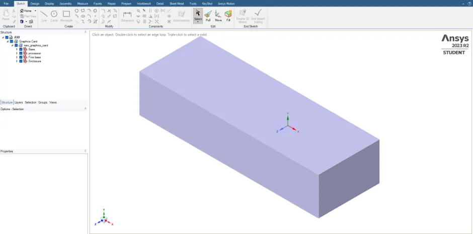
2) Go to workbench and select share topology. With Share topology enabled we will have proper meshing at the interface between 2 bodies.
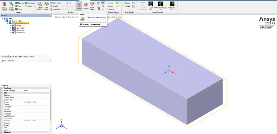
For Conjugate heat transfer analysis of graphics card, we will conduct 4 cases.
1st Case: Default meshing with air velocity of 1 m/s.
2nd Case: Refined meshing with air velocity of 1 m/s.
3rd Case: Refined meshing with air velocity of 3 m/s.
4th Case: Refined meshing with air velocity of 5 m/s.
1st Case:
a) Meshing:
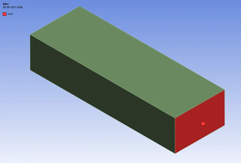
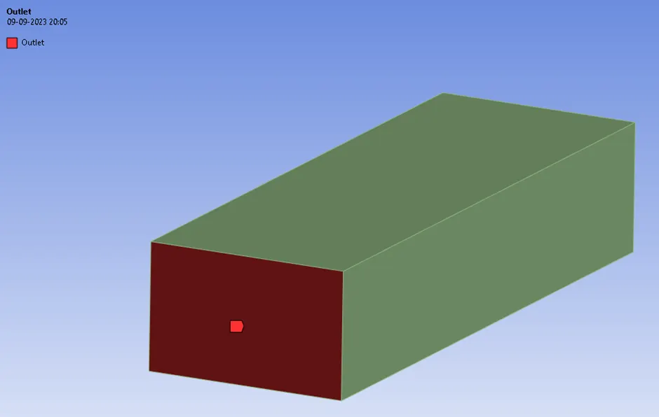
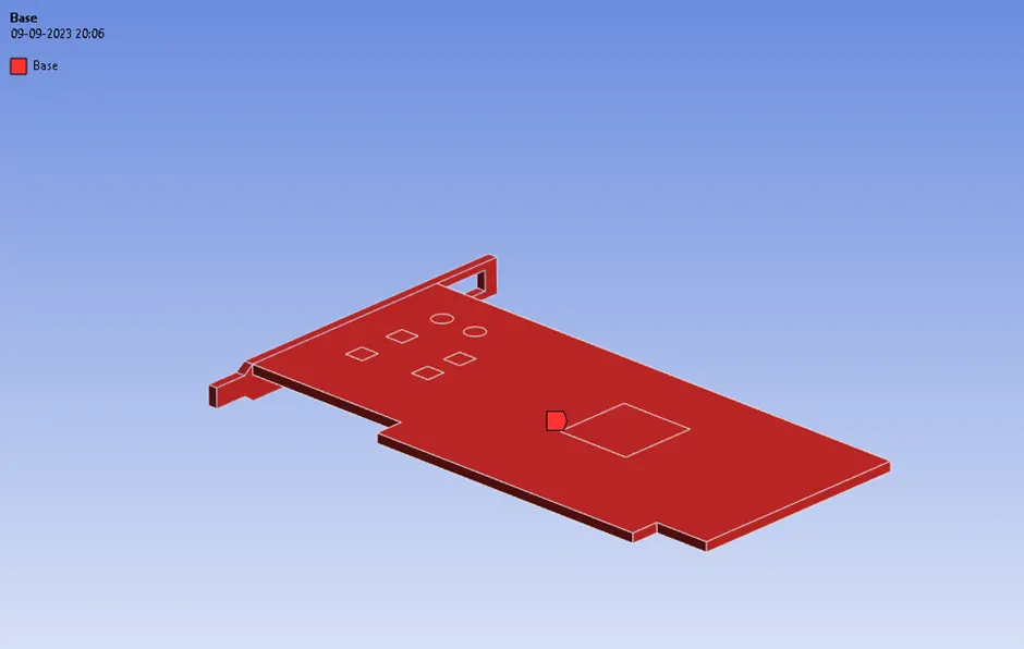
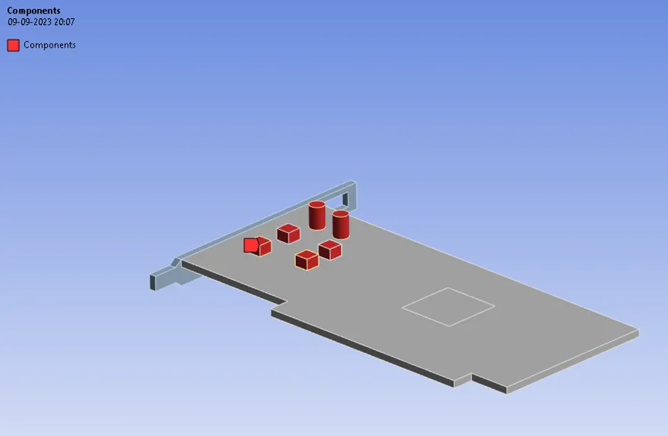
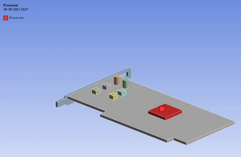
1) In Meshing workbench, we will first create Named Ref for the bodies. Those are as below.
Inlet
Outlet
>
<>< alt>
Components
Processor
>
<>< src alt="">
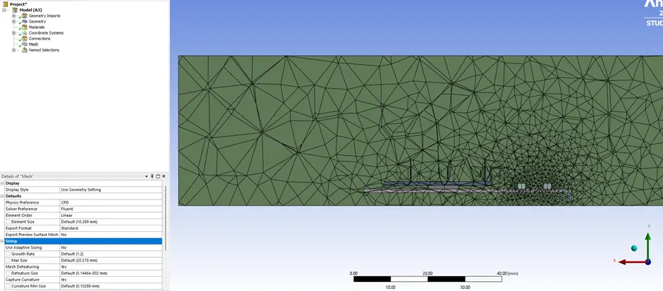
2) Once named ref is done, we will generate a default mesh as below
b) Processing:
1) Once meshing is done, we can move ahead with the setup
< src alt="">
<!--[endif]-->
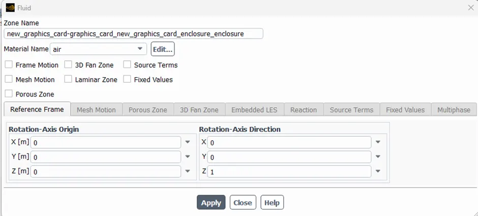
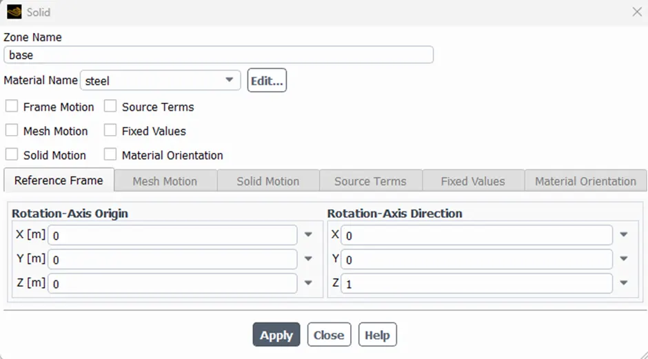
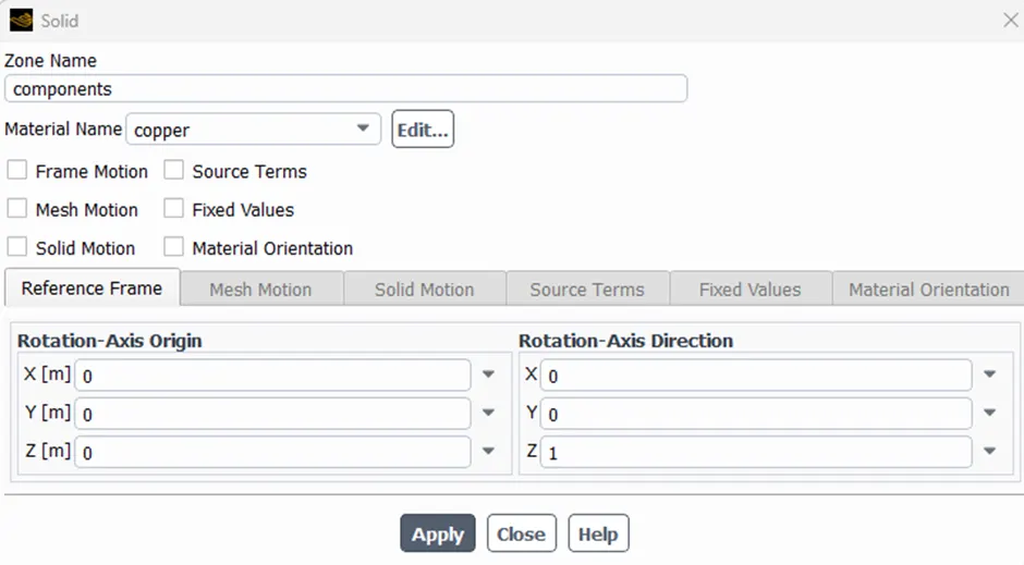
2) Before setting up the physics, we should determine the materials for various components. Material decided are listed below.
Fluid: Air
<!--[endif]-->
Base: Steel
<!--[endif]-->
Components: Copper
<!--[endif]-->
Fins: Aluminium
< src alt="">
<!--[endif]-->
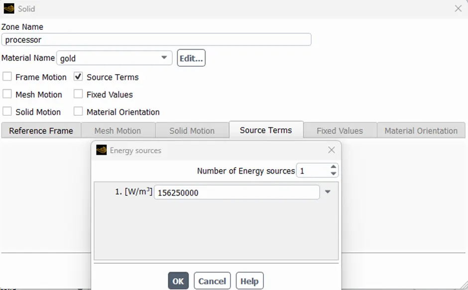
Processor: Gold
< src alt="">
<!--[endif]-->
For Processor, we will add source terms as it will produce energy.
For this analysis, we are assuming the processor is working at 10 Watts. So, the energy is calculated as below.
Energy = 10 * 10^9 / (8*8*1) = 156,250,000 W/m^3
<!--[endif]-->
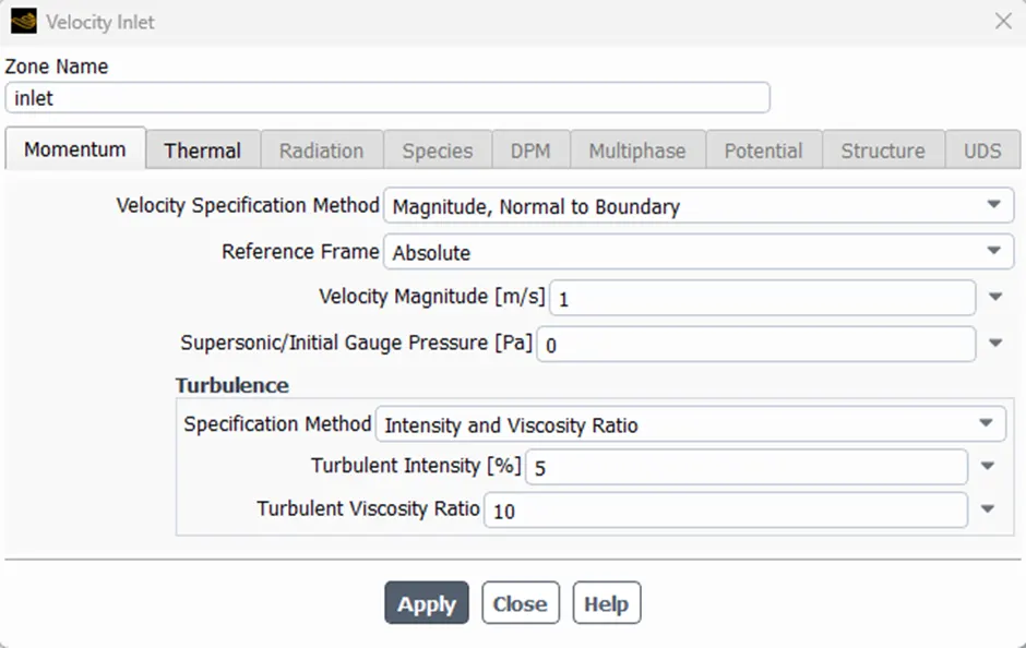
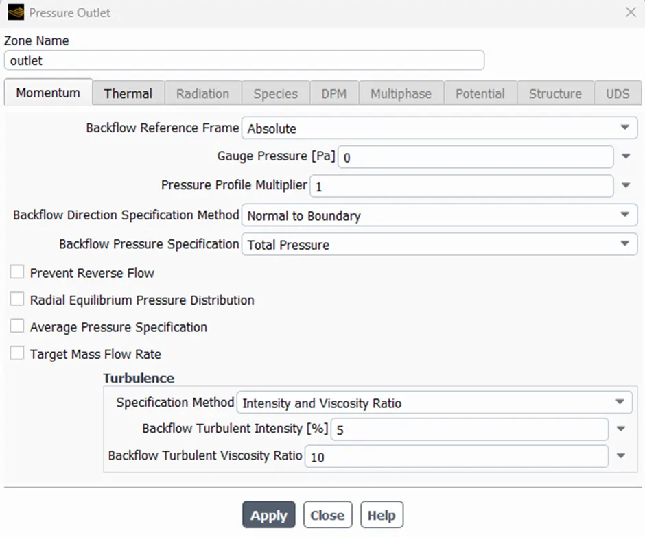
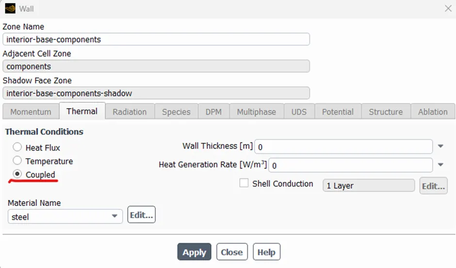
3) Now we will set up physics and boundary condition.
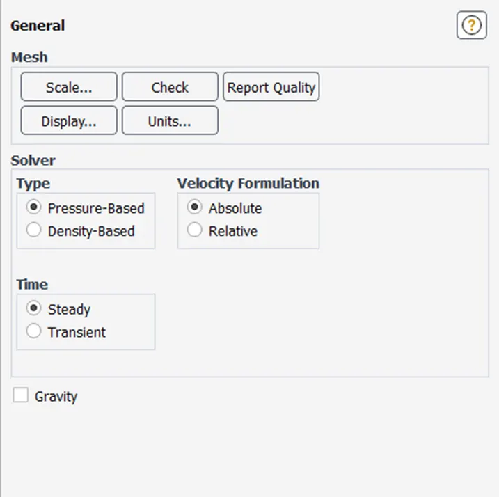
<!--[endif]-->

Inlet Air Velocity: 1 m/s at 300 K<!--[endif]-->

Outlet BC
<!--[endif]-->
Need to make sure all the walls are coupled
<!--[endif]-->
c) Solution:
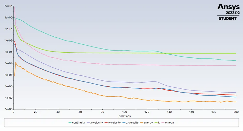
Residual Chart
<!--[endif]-->
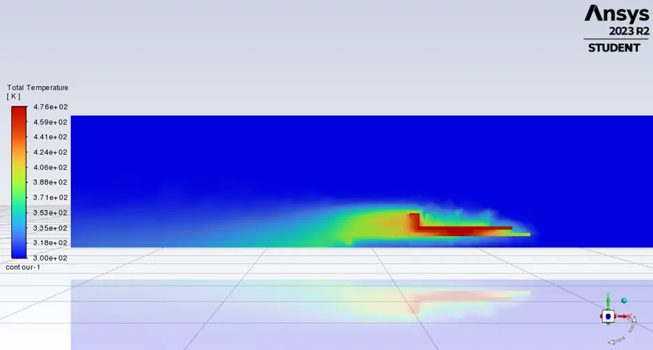
Total Temperature Contour
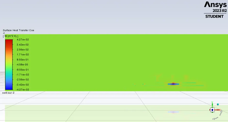
Heat Transfer Coeff
<!--[endif]-->
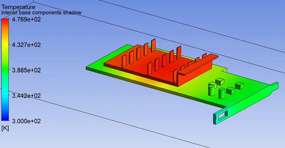
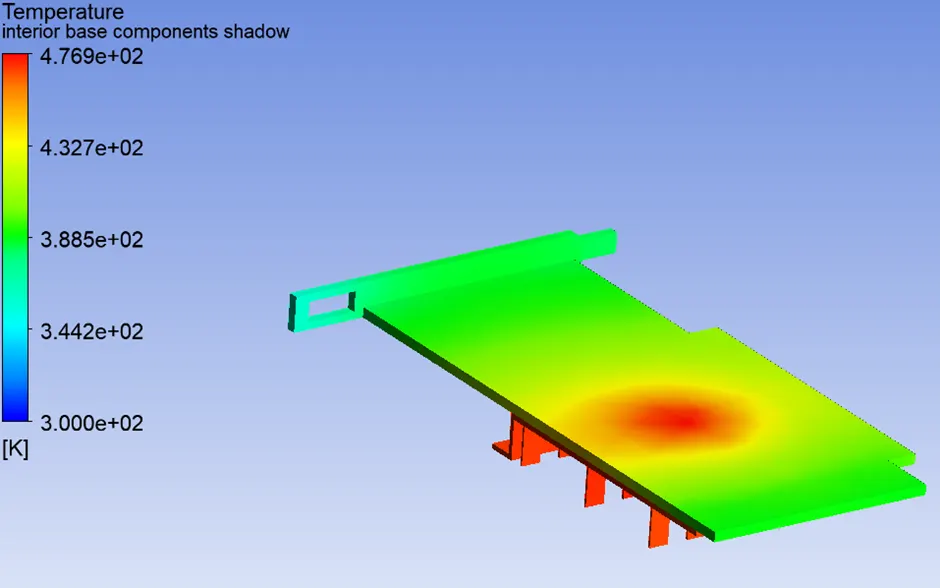
Temperature Hotspots
<!--[endif]-->
2nd Case:
a) Meshing
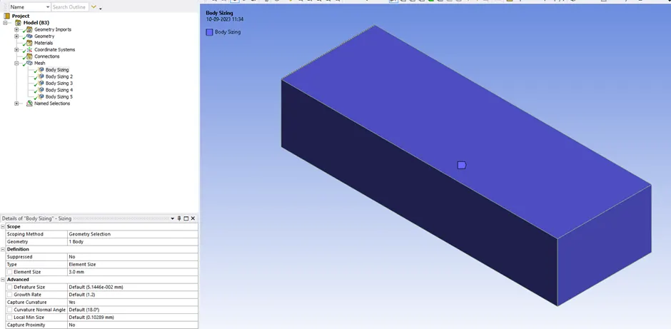
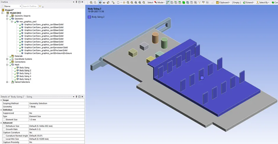
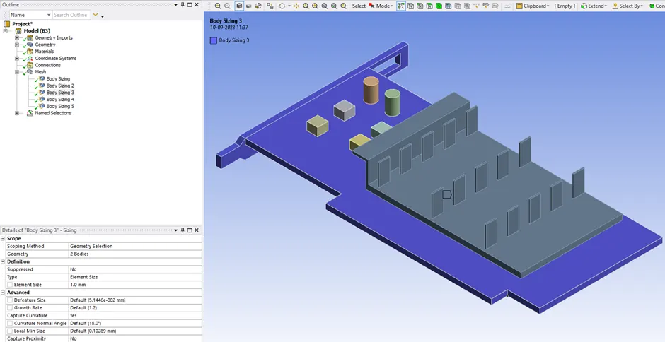
1) For this case we will refine the mesh as follows
Enclosure mesh size: 3mm
<!--[endif]-->
Fins mesh size: 1mm
<!--[endif]-->
Base mesh size: 1mm
<!--[endif]-->
Components mesh size: 0.3mm
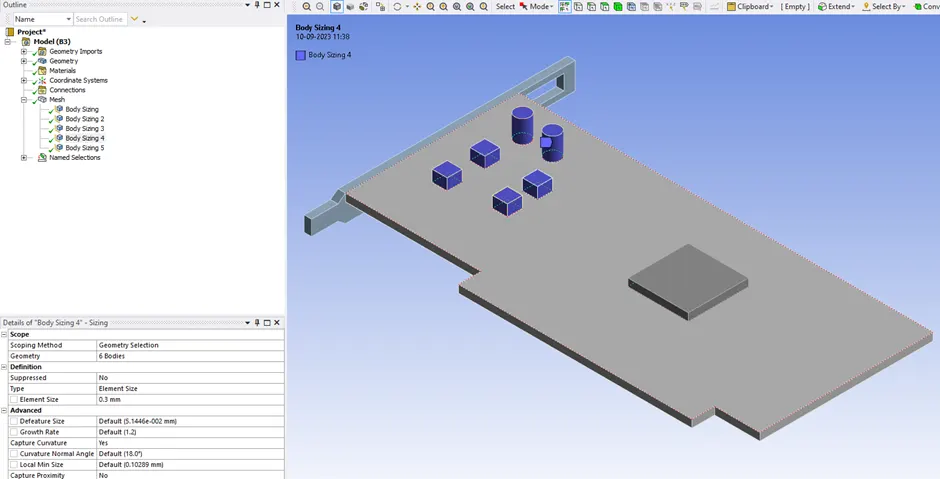
<!--[endif]-->
Processor mesh size: 0.3mm
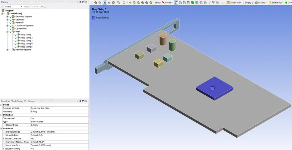
<!--[endif]-->
2) Total Mesh elements: 454801
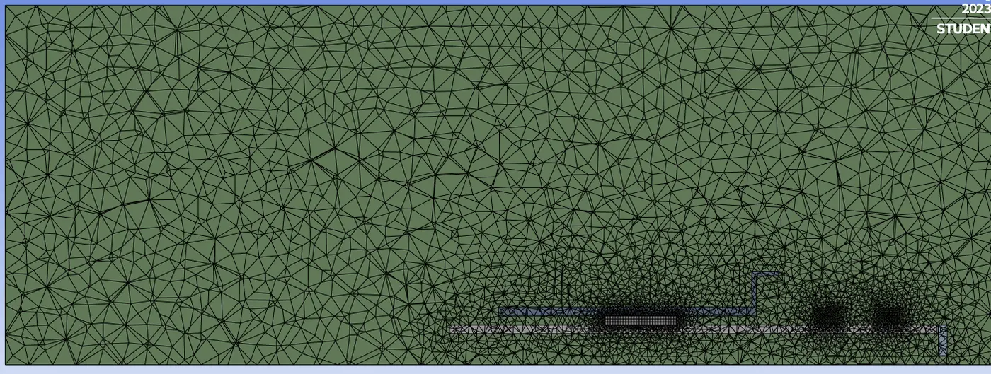
<!--[endif]-->
b) Processing:
Setup for this case will be same as previous case.
c) Solution:
Residual Chart
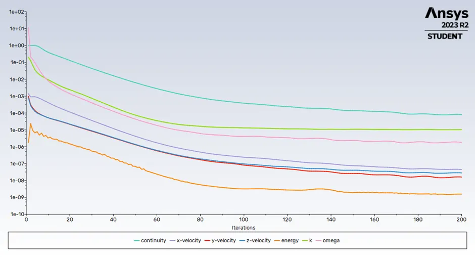
<!--[endif]-->
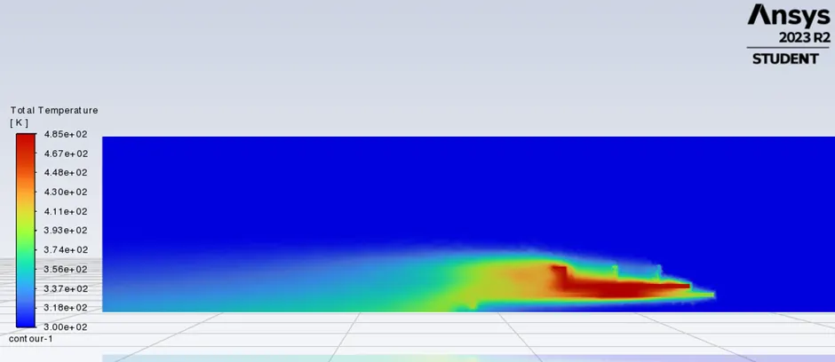
Total Temperature Contour:
<!--[endif]-->
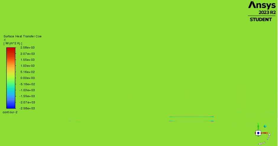
Heat Transfer Coeff
<!--[endif]-->
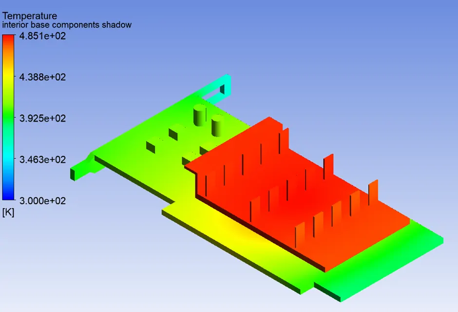
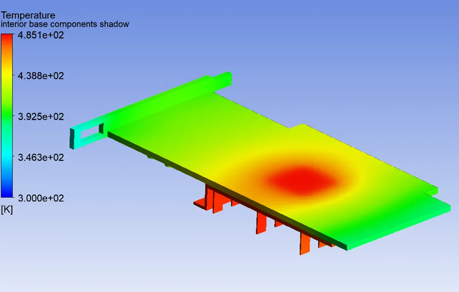
Temperature hotspots:
<!--[endif]-->
<!--[endif]-->
3rd Case:
a) Meshing:
Meshing will be same as 2nd Case.
b) Processing:
We will update the air inlet velocity to 3 m/s at 300 K.
c) Solution:
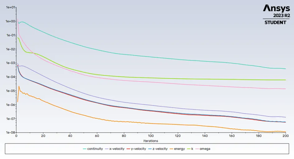
Residual Chart:
<!--[endif]-->
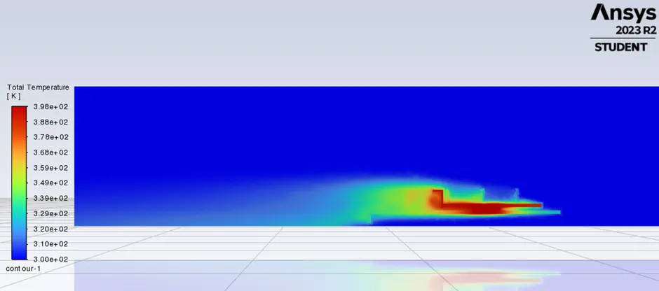
Total Temperature Contours:
<!--[endif]-->
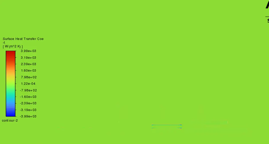
Heat Transfer coeff:
<!--[endif]-->
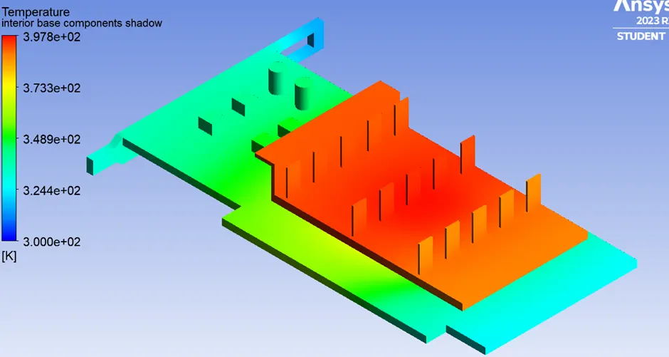
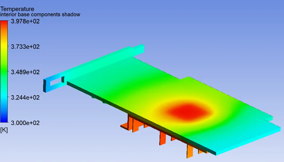
Temperature Hotspots:
<!--[endif]-->
<!--[endif]-->
4th Case:
a) Meshing:
Meshing will be same as 2nd Case.
b) Processing:
We will update the air inlet velocity to 5 m/s at 300 K.
c) Solution:
Residual Chart:

<!--[endif]-->
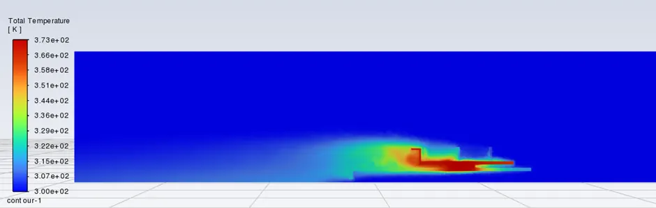
Total Temperature Contours:
<!--[endif]-->
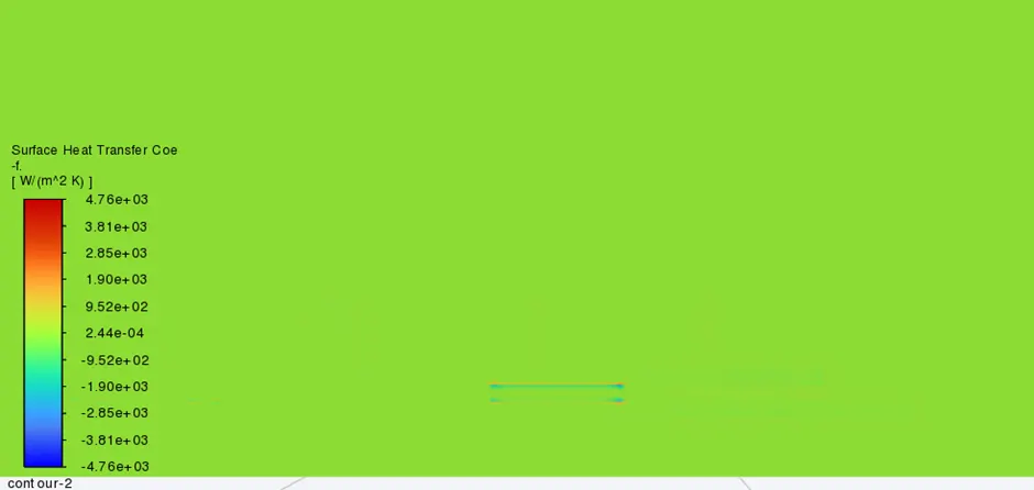
Heat Transfer coeff:
<!--[endif]-->
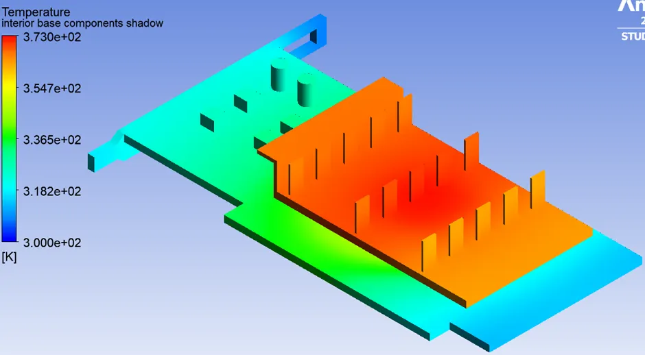
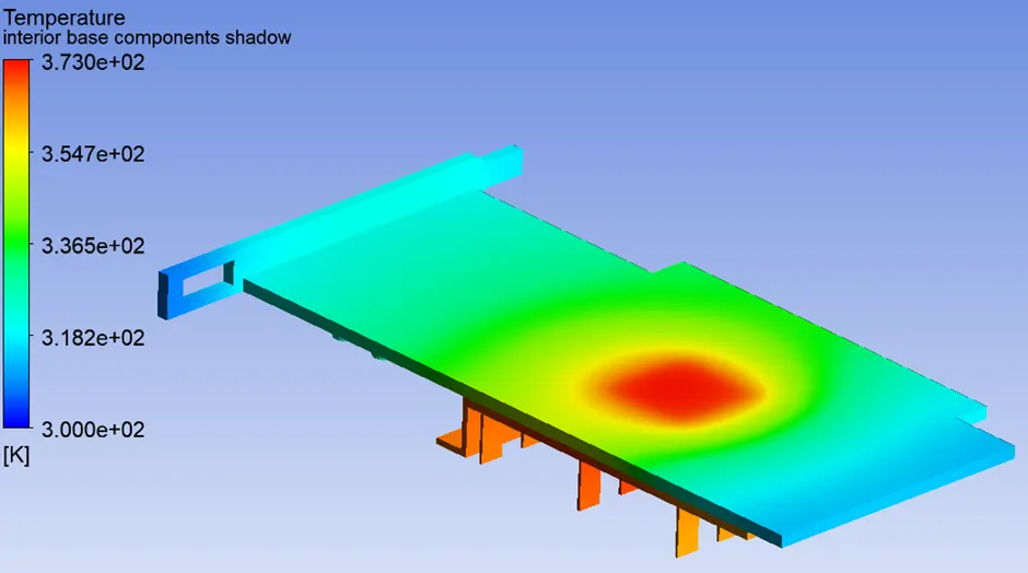
Temperature Hotspots:
<!--[endif]-->
 <!--[endif]-->
Results:
|
Case |
Mesh Elements |
Velocity |
Max Temperature |
Heat Transfer Coeff |
|
1st Case |
83941 |
1 m/s |
476 K |
427 W/(m^2K) |
|
2nd Case |
454801 |
1 m/s |
485 K |
2580 W/(m^2K) |
|
3rd Case |
454801 |
3 m/s |
398 K |
3990 W/(m^2K) |
|
4th Case |
454801 |
5 m/s |
373 K |
4760 W/(m^2K) |
Conclusion:
1) When we compare case 1 and case 2, we can see that with a finer mesh we get a realistic and refined value compared o coarser mesh. Also, the results near the wall looks much better in refined mesh condition.
2) We can observe from above results that, as the velocity of air increases the max temperature attained by the processor decreases.
3) The hotspot region for the graphic card is near the processor as it is source of heat in the assembly.
4) The temperature of fins away from the inlet is more compared to the one near inlet as there is a direct contact of cool air at the front. Also, temperature at the recirculation area is low due low air velocity which results in poor transfer of heat.
5) This study will help us to redesign some components for more efficient heat transfer in the graphic card.