Week 3 Challenge : CFD meshing on Turbocharger
Aim: To create Surface mesh and Volumetric mesh of a turbo charger.
Procedure:
- Once Turbo charger is loaded in ANSA, we must first proceed with surface correction using Topo deck:
- As we see some overlapped surfaces, I deleted those by carefully inspecting the surface needed and the surface that are extra.
- After that, I corrected all the single cons by adding the faces where needed. Also, used topo option under faces wherever two faces were not connected.
- For Volumetric Mesh, as we needed the volume where the fluid will flow, the PID’s needed to be connected to one another to create volume. So, the PID’s were connected using TOPO or by projecting Cons.
- Once the surface correction is done, we move on to Surface Mesh:
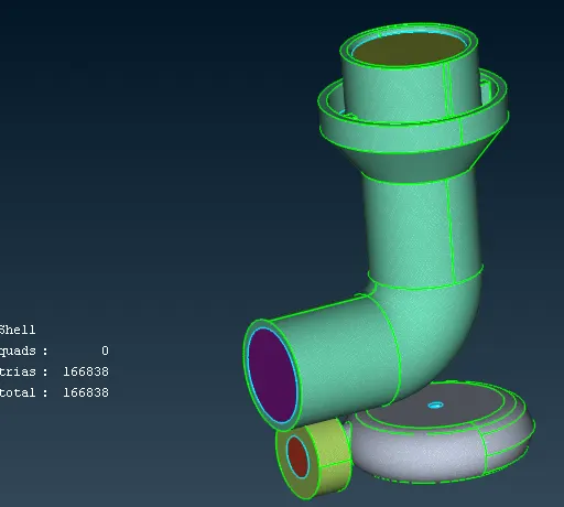
- As per the input Turbo casing, compressor casing and inlet casing cover has mesh length of 5 mm.
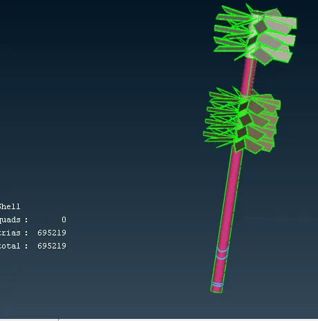
- As per the input Shaft, Blade stage1 and Blade stage2 has a mesh length of 1 mm.
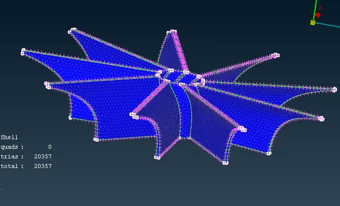
- As per the input Impeller has a mesh length of 2 mm.
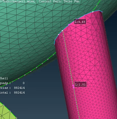
- But as all this PID’s are linked to each other, a varying mesh length is created for shaft to accommodate those connections. Please refer the pic below.
- After surface mesh we move onto Volumetric Mesh:
- After defining the surface mesh go to Volumetric Mesh deck, Click Define under Volumes.
- A list of auto detected volumes will be shown, Delete the volumes that are detected for the thickness of materials, as fluid won’t flow in those areas. You will be left with Volumes shown below.
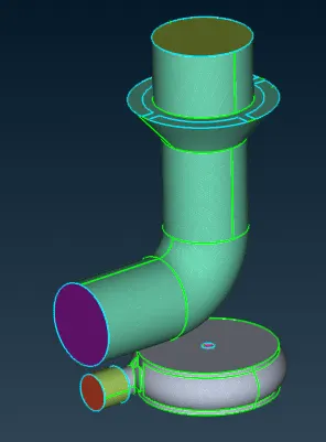
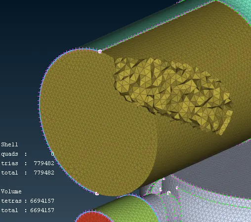
- Give CFD Tetra mesh to the Volume and the meshing is done. Below is a pic with some mesh elements hidden to give a perspective of how it looks like
Learning Outcome:
- Gained more experience in Surface clean up using topo deck.
- Learned how to give varied mesh length
- Got to know the basics of Volumetric Mesh generation
Conclusion:
3rd week challenge helped me understand the basics of volumetric meshing